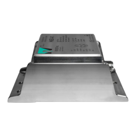
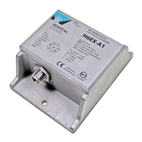
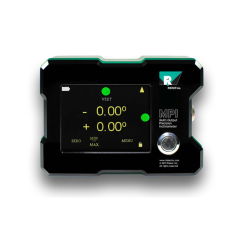
RIEKER H6 User manual

User Programmable
Digital RS485
Current 0..24mA
Voltage 0..10V
Open Collector Switch
Dual & Single Axis
Up to 360º
Sensor
Specifications,
Installation
,
& Wiring
2018
Flex™ H6 User Guide

Flex™ H6 User Guide
Page 1 of 29
RIEKER INC • 34 MOUNT PLEASANT ROAD • ASTON • PA • 19014 • USA
610-500-2000 fax: 610-500-2002 [email protected] www.riekerinc.com
The information and material presented may not be published, broadcast, rewritten, or redistributed without the expressed wri
tten consent of Rieker
®
Inc.
The content presented is provided for informational purposes only and subject to change.
©201
7 Rieker®All Rights Reserved.
FORM NUMBER: H60009_12/14 UPDATED:
5/15/18
Table of Contents
Sensor Description...................................................................................................................................3
Updates & Revision History .....................................................................................................................3
Sensor Specifications...............................................................................................................................4
Sensor Specifications, Continued ............................................................................................................5
H6 Installation and Wiring ........................................................................................................................6
Horizontal Mount Axis Orientations .................................................................................................8
Vertical Mount Axis Orientations .....................................................................................................8
H6 Connector Wiring Tables..............................................................................................................11
H6 RS485 Bus Wiring Configurations ...............................................................................................12
Analog Outputs ......................................................................................................................................14
Output Axis Mapping .........................................................................................................................14
Output Types .....................................................................................................................................14
Current Output...............................................................................................................................14
Voltage Output...............................................................................................................................14
Switch Output ................................................................................................................................14
Sensitivity & Zero Angle Calculation (Voltage and Current Outputs Only)........................................15
Wiring Diagrams and Connection Procedures ..................................................................................16
Wiring for a Current Output ...........................................................................................................16
Wiring for a Voltage Output ...........................................................................................................18
Wiring for a Switch Output.............................................................................................................19
Digital RS485 Communications .............................................................................................................20
RS485 Protocol..................................................................................................................................20
Packet Format ...............................................................................................................................20
RS485 Command Functions..............................................................................................................21
Function Descriptions ....................................................................................................................22
Appendix A. Creating an H6 Development Cable..................................................................................29

Flex™ H6 User Guide
Page 2 of 29
RIEKER INC • 34 MOUNT PLEASANT ROAD • ASTON • PA • 19014 • USA
610-500-2000 fax: 610-500-2002 [email protected] www.riekerinc.com
The information and material presented may not be published, broadcast, rewritten, or redistributed without the expressed wri
tten consent of Rieker
®
Inc.
The content presented is provided for informational purposes only and subject to change.
©201
7 Rieker®All Rights Reserved.
FORM NUMBER: H60009_12/14 UPDATED:
5/15/18
List of Figures
F
IGURE
1:
H6
D
IMENSIONS
,
M
OUNTING
,
A
ND
A
XES
T
ILT
O
RIENTATION
(I
NCHES
[M
M
]) ..................................................... 6
F
IGURE
2:
E
XAMPLE
O
F
S
ERIAL
N
UMBER
A
ND
F
ACTORY
D
EFAULT
C
ONFIGURATION
L
ABEL
............................................... 9
F
IGURE
3:
S
INGLE
H6
S
ENSOR
................................................................................................................................. 12
F
IGURE
4:
M
ULTIPLE
D
AISY
-C
HAIN
H6
S
ENSORS
........................................................................................................ 12
F
IGURE
5:
M
ULTIPLE
M
ULTI
-D
ROP
H6
S
ENSORS
........................................................................................................ 12
F
IGURE
6:
M
AX
N
UMBER
O
F
D
AISY
C
HAIN
H6
S
G
RAPH
............................................................................................... 13
F
IGURE
7:
C
URRENT
W
IRING
D
IAGRAMS
..................................................................................................................... 17
F
IGURE
8:
V
OLTAGE
W
IRING
D
IAGRAMS
..................................................................................................................... 18
F
IGURE
9:
S
WITCH
W
IRING
D
IAGRAMS
........................................................................................................................ 19
List of Tables
T
ABLE
1:
R
EVISION
H
ISTORY
....................................................................................................................................... 3
T
ABLE
2:
H6
M
ALE
8-P
IN
I
NPUT
C
ONNECTOR
W
IRING
................................................................................................. 11
T
ABLE
3:
H6
F
EMALE
5-P
IN
D
IGITAL
O
UTPUT
D
AISY
C
HAIN
C
ONNECTOR
W
IRING
.......................................................... 11
T
ABLE
4:
H6
C
URRENT
S
ENSE
.................................................................................................................................. 16
T
ABLE
4:
F
UNCTION
L
IST
.......................................................................................................................................... 21

Flex™ H6 User Guide
Page 3 of 29
RIEKER INC • 34 MOUNT PLEASANT ROAD • ASTON • PA • 19014 • USA
610-500-2000 fax: 610-500-2002 [email protected] www.riekerinc.com
The information and material presented may not be published, broadcast, rewritten, or redistributed without the expressed wri
tten consent of Rieker
®
Inc.
The content presented is provided for informational purposes only and subject to change.
©201
7 Rieker®All Rights Reserved.
FORM NUMBER: H60009_12/14 UPDATED:
5/15/18
Sensor Description
The H6 Flex™ inclinometer provides highly accurate, dual axis inclination over a range of 180°. These sensors
incorporate MEMS accelerometers referenced to gravity with integrated temperature compensation over the
full industrial operating range of -40° to +85°C for absolute accuracy. They have both digital RS485 and analog
outputs. Both outputs are linear with respect to the input angle directly.
The digital RS485 output uses two-wire, half duplex communication, along with a Rieker specific protocol. This
protocol can be used to measure the angle of both axes, as well as configure the various digital and analog
parameters of the sensor.
The H6 provides two continuous, fully configurable, analog outputs. These outputs can be individually set to
current, voltage or open collector switch modes. Each analog output can be mapped to either axis.
The voltage output can be set to any value between 0V and 10V and to any angle range between 180°. The
current output can be set to any value between 0mA and 24mA and to any angle range between 180°. The
open collector switch output connects to signal common and can be set to trip above, below, between, or
outside any angle threshold or window range. Each open collector switch can drive up to 250mA (to be used
directly or to drive an external relay).
Also as an optional enhancement, the H6 has to ability to log angle data to a microSD card.
Updates & Revision History
The information in this guide may be subject to change. Please visit www.riekerinc.com for latest version of
this document.
T BLE 1: REVISION HISTORY
REV DATE DESCRIPTION
A 3/14/2018 Initial Release

Flex™ H6 User Guide
Page 4 of 29
RIEKER INC • 34 MOUNT PLEASANT ROAD • ASTON • PA • 19014 • USA
610-500-2000 fax: 610-500-2002 [email protected] www.riekerinc.com
The information and material presented may not be published, broadcast, rewritten, or redistributed without the expressed wri
tten consent of Rieker
®
Inc.
The content presented is provided for informational purposes only and subject to change.
©201
7 Rieker®All Rights Reserved.
FORM NUMBER: H60009_12/14 UPDATED:
5/15/18
Sensor Specifications
INPUT PARAMETERS
SUPPLY VOLTAGE +11..36 VDC Non-Regulated
SUPPLY CURRENT
1
22mA @ 24VDC (Digital Output only)
30mA nominal @ 24VDC (Analog Output - no load)
75mA max @ 24VDC (Analog and Digital Outputs enabled)
85mA max @ 12VDC (Analog and Digital Outputs enabled)
ANALOG MEASURING RANGE Scalable within 360°
DIGITAL MEASURING RANGE ±180°
INPUT PROTECTION Reverse Polarity, ESD & Surge Protected
ABSOLUTE ACCURACY OVER FULL OPERATING TEMPERATURE
RANGE: ±180° ±0.1º typical, ±0.2º absolute max
RESOLUTION 0.05º
RESPONSE TIME
6 user-configurable options from 4Hz to 0.3Hz
CURRENT & VOLTAGE OUTPUT PARAMETERS
OUTPUT RANGES
Current 4..20 mA, 0..20 mA
(Configurable within 0..24mA)
Voltage 0..5 V, 0..10V
(Configurable within 0..10V) 1kΩload min.
SENSITIVITY
2
Relative to Scaled Range
NULL (0º) Fully Configurable
SWITCH OUTPUT PARAMETERS
OUTPUT MODE Open Collector Switch to Signal Common
TRIP MODES Fully Configurable (Window, Threshold, etc.)
SWITCH CAPABILITY 250mA @ 36V max
DIGITAL OUTPUT PARAMETERS
OUTPUT TYPE RS-485 Half Duplex (2-wire)
INCLINATION OUTPUT 32-Bit IEEE Packetized Float
BAUD RATE 125K Default (Configurable from 9600 to 250K)
INFORMATION RATE Polled (up to 20 times/sec)
LOGGING CAPABILITY (OPTIONAL)
SUPPLY CURRENT Additional 20mA @24VDC
LOGGING RESOLUTION Configurable in one minute increments
CARD TYPE µSD
Notes:
1. Supply Current varies depending on outputs connected. Digital output only assumes analog output section is always
active however current loop is not connected.
2. See Sensitivity & Zero Angle Calculation (Voltage and Current Outputs Only)

Flex™ H6 User Guide
Page 5 of 29
RIEKER INC • 34 MOUNT PLEASANT ROAD • ASTON • PA • 19014 • USA
610-500-2000 fax: 610-500-2002 [email protected] www.riekerinc.com
The information and material presented may not be published, broadcast, rewritten, or redistributed without the expressed wri
tten consent of Rieker
®
Inc.
The content presented is provided for informational purposes only and subject to change.
©201
7 Rieker®All Rights Reserved.
FORM NUMBER: H60009_12/14 UPDATED:
5/15/18
Sensor Specifications, Continued
TEMPERATURE RANGES
OPERATING TEMPERATURE -40ºF..+185ºF (-40ºC..+85ºC)
STORAGE TEMPERATURE -49ºF..+194ºF (-45ºC..+90ºC)
MECHANICAL CHARACTERISTICS
HOUSING Aluminum, IP68, All-weather, Submersible
WEIGHT 18.6 oz. (525 Grams)
MOUNTING HOLES Accept #8 or M4.5 screws (See Dimensional Drawing)
MOUNTING PLANE Flat Horizontal or Vertical Surface
OUTLINE DIMENSIONS 4.34” x 3.26” x 1.8” [110mm x 82.8mm x 45.7mm]
ELECTRICAL CONNECTION See Electrical Connection Drawing

Flex™ H6 User Guide
Page 6 of 29
RIEKER INC • 34 MOUNT PLEASANT ROAD • ASTON • PA • 19014 • USA
610-500-2000 fax: 610-500-2002 [email protected] www.riekerinc.com
The information and material presented may not be published, broadcast, rewritten, or redistributed without the expressed wri
tten consent of Rieker
®
Inc.
The content presented is provided for informational purposes only and subject to change.
©201
7 Rieker®All Rights Reserved.
FORM NUMBER: H60009_12/14 UPDATED:
5/15/18
H6 Installation and Wiring
Notes:
•The factory default settings for mounting position (either horizontal or vertical) must be selected at
time of order.
•Default output polarity shown is configurable at the factory (defined at time of order) or by the end
user via the Flex Dev Kit that includes Rieker Flexware app, sold separately.
•Special H6-MM Multi-Mount model (available exclusively through Digi-Key) allows the end user to
select between horizontal and vertical mounting positions via a special Flex Dev Kit that includes
Rieker Flexware app, sold separately through Digi-key.
1.
On the mounting plane, prepare surface with three tapped holes 3.815” [96.9mm] apart for #9
mounting screws. NOTE that the single hole on side with the two slots is not meant to be used for
mounting
2.
Mount inclinometer to mounting plane using #9 mounting screws.
FIGURE 1: H6 Dimensions and Mounting (Inches [Mm])

Flex™ H6 User Guide
Page 7 of 29
RIEKER INC • 34 MOUNT PLEASANT ROAD • ASTON • PA • 19014 • USA
610-500-2000 fax: 610-500-2002 [email protected] www.riekerinc.com
The information and material presented may not be published, broadcast, rewritten, or redistributed without the expressed wri
tten consent of Rieker
®
Inc.
The content presented is provided for informational purposes only and subject to change.
©201
7 Rieker®All Rights Reserved.
FORM NUMBER: H60009_12/14 UPDATED:
5/15/18
FIGURE 2: Mounting Positions

Flex™ H6 User Guide
Page 8 of 29
RIEKER INC • 34 MOUNT PLEASANT ROAD • ASTON • PA • 19014 • USA
610-500-2000 fax: 610-500-2002 [email protected] www.riekerinc.com
The information and material presented may not be published, broadcast, rewritten, or redistributed without the expressed wri
tten consent of Rieker
®
Inc.
The content presented is provided for informational purposes only and subject to change.
©201
7 Rieker®All Rights Reserved.
FORM NUMBER: H60009_12/14 UPDATED:
5/15/18
Horizontal Mount xis Orientations
As shown in the top drawing of
, the 0° orientation for a horizontal mount H6 is a desktop level position.
•For the X-axis, looking at the unit from the side with the connector facing to the right, a clockwise
rotation from the zero position is considered positive and a counter-clockwise rotation from the zero
position is considered negative.
•For the Y-axis, looking at the unit from the front with the connector facing towards you, a clockwise
rotation from the zero position is considered positive and a counter-clockwise rotation from the zero
position is considered negative.
Vertical Mount xis Orientations
As shown in the bottom drawing of
Figure 2: Mounting Positions

Flex™ H6 User Guide
Page 9 of 29
RIEKER INC • 34 MOUNT PLEASANT ROAD • ASTON • PA • 19014 • USA
610-500-2000 fax: 610-500-2002 [email protected] www.riekerinc.com
The information and material presented may not be published, broadcast, rewritten, or redistributed without the expressed wri
tten consent of Rieker
®
Inc.
The content presented is provided for informational purposes only and subject to change.
©201
7 Rieker®All Rights Reserved.
FORM NUMBER: H60009_12/14 UPDATED:
5/15/18
, the 0° orientation for a vertical mount H6 is with the connector facing down.

Flex™ H6 User Guide
Page 10 of 29
RIEKER INC • 34 MOUNT PLEASANT ROAD • ASTON • PA • 19014 • USA
610-500-2000 fax: 610-500-2002 [email protected] www.riekerinc.com
The information and material presented may not be published, broadcast, rewritten, or redistributed without the expressed wri
tten consent of Rieker
®
Inc.
The content presented is provided for informational purposes only and subject to change.
©201
7 Rieker®All Rights Reserved.
FORM NUMBER: H60009_12/14 UPDATED:
5/15/18
•For the X-axis, looking at the unit from the top with the connector facing down, a clockwise rotation
from the zero position is considered positive and a counter-clockwise rotation from the zero position is
considered negative.
•For the Y-axis, looking at the unit from the side with the top facing to the right and the connector
facing down, a clockwise rotation from the zero position is considered positive and a counter-
clockwise rotation from the zero position is considered negative.
FIGURE 2: Example of Serial Number and Factory Default Configuration Label
NOTE: Located on the bottom of the h6 sensor, the label provides the factory configured defaults and serial
number.

Flex™ H6 User Guide
Page 11 of 29
RIEKER INC • 34 MOUNT PLEASANT ROAD • ASTON • PA • 19014 • USA
610-500-2000 fax: 610-500-2002 [email protected] www.riekerinc.com
The information and material presented may not be published, broadcast, rewritten, or redistributed without the expressed wri
tten consent of Rieker
®
Inc.
The content presented is provided for informational purposes only and subject to change.
©201
7 Rieker®All Rights Reserved.
FORM NUMBER: H60009_12/14 UPDATED:
5/15/18
H6 Connector Wiring Tables
T BLE 2: H6 M LE 8-PIN INPUT CONNECTOR WIRING
PIN FUNCTION TERMINATION
1 SUPPLY VOLTAGE +11.. +36VDC WHITE
2 POWER / SIGNAL COMMON BROWN
3 RS485 D+ GREEN
4 RS485 D- YELLOW
5 NO CONNECTION GRAY
6 ANALOG OUTPUT 1 (DEFAULT: X AXIS) PINK
7 ANALOG OUTPUT 2 (DEFAULT: Y AXIS) BLUE
8 NO CONNECTION RED
NOTES:
•The front and back of the connector may not
have any pin markings in the actual connector.
The user will need to look at the front-side
keyway (see drawing) to determine pin outs.
•The termination wire colors reference the cable
sold by Rieker.
T BLE 3: H6 FEM LE 5-PIN DIGIT L OUTPUT D ISY CH IN CONNECTOR WIRING
PIN FUNCTION
1 NO CONNECTION
2 SUPPLY VOLTAGE +11..+36VDC
3 POWER COMMON
4 RS-485 D+
5 RS-485 D-
NOTE: The H6 Sensor’s Chassis Ground is NOT the same as the signal ground for the current output return. The
current output return must be connected to the POWER/SIGNAL COMMON (pin 2).

Flex™ H6 User Guide
Page 12 of 29
RIEKER INC • 34 MOUNT PLEASANT ROAD • ASTON • PA • 19014 • USA
610-500-2000 fax: 610-500-2002 [email protected] www.riekerinc.com
The information and material presented may not be published, broadcast, rewritten, or redistributed without the expressed wri
tten consent of Rieker
®
Inc.
The content presented is provided for informational purposes only and subject to change.
©201
7 Rieker®All Rights Reserved.
FORM NUMBER: H60009_12/14 UPDATED:
5/15/18
H6 RS485 Bus Wiring Configurations
When using the digital output, the H6 sensor can be connected as a single sensor or can be connected to other
sensors in a bus configuration. The following figures show three possible configurations for using the H6 sensor
with the digital output.
FIGURE 3: Single H6 Sensor
FIGURE 4: Multiple Daisy-Chain H6 Sensors
FIGURE 5: Multiple Multi-Drop H6 Sensors
PC
USB to
RS485
Power
120Ω Termination required at ends of bus
PC USB to
RS485
Power
120Ω Termination required at ends of bus
PC USB to
RS485
Power
120Ω Termination required at ends of bus

Flex™ H6 User Guide
Page 13 of 29
RIEKER INC • 34 MOUNT PLEASANT ROAD • ASTON • PA • 19014 • USA
610-500-2000 fax: 610-500-2002 [email protected] www.riekerinc.com
The information and material presented may not be published, broadcast, rewritten, or redistributed without the expressed wri
tten consent of Rieker
®
Inc.
The content presented is provided for informational purposes only and subject to change.
©201
7 Rieker®All Rights Reserved.
FORM NUMBER: H60009_12/14 UPDATED:
5/15/18
FIGURE 6: Max Number of Daisy Chain H6s Graph
NOTE: This graph is based on 22AWG wire as the daisy-chain between sensors. Also note that by using a multi-
drop configuration, additional sensors may be added, up to a maximum of 60 units due to bus loading.

Flex™ H6 User Guide
Page 14 of 29
RIEKER INC • 34 MOUNT PLEASANT ROAD • ASTON • PA • 19014 • USA
610-500-2000 fax: 610-500-2002 [email protected] www.riekerinc.com
The information and material presented may not be published, broadcast, rewritten, or redistributed without the expressed wri
tten consent of Rieker
®
Inc.
The content presented is provided for informational purposes only and subject to change.
©201
7 Rieker®All Rights Reserved.
FORM NUMBER: H60009_12/14 UPDATED:
5/15/18
nalog Outputs
The H6 sensor comes with two, continuous, fully configurable, analog outputs. The analog outputs are directly
related to the input angle and will match the angle for any configured range. The factory default output
parameters for each analog output can be separately reconfigured at time of order, and/or can be fully
reconfigured by the end user when using the Dev Kit and Flexware™ Sensor Configurator (sold separately).
C UTION: The Flex™ series of sensors are manufactured to allow end user adjustments of the analog and digital
output parameters. Purchaser assumes the responsibility of ensuring that the settings are appropriate for their
specific application. IN NO EVENT WILL RIEKER BE LIABLE FOR CONSEQUENTIAL OR INCIDENTAL DAMAGES OF ANY
KIND.
Output xis Mapping
Each analog output can be individually mapped to correspond to either axis (X or Y). The default is that output
1 corresponds to the X-axis and output 2 corresponds to the Y-axis.
Output Types
Each analog output can be individually set to one of three analog output types: Current, Voltage, or Switch.
Current Output
An output configured for current has four configurable parameters: minimum current, maximum current,
minimum angle, and maximum angle. Min and max current each can be set to any range within 0mA and 24mA,
where max must be greater than min. The most common option is Min = 4mA and Max = 20mA.
Min angle is the angle corresponding to minimum current. Max angle is the angle corresponding to maximum
current. Min and max can each be set to any angle range within the entire ±180° operating range. A reversed
polarity is achieved by setting min angle greater than max angle.
Voltage Output
An output configured for voltage has four configurable parameters: minimum voltage, maximum voltage,
minimum angle, and maximum angle. Min and max voltage each can be set to any range within 0V and 10V,
where max must be greater than min. Two common option are Min = 0V & Max = 5V and Min = 0V & Max = 10V.
Min angle is the angle corresponding to minimum voltage. Max angle is the angle corresponding to maximum
voltage. Min and max can each be set to any angle range within the entire ±180° operating range. A reversed
polarity is achieved by setting min angle greater than max angle.
Switch Output
Each switch output is an open collector, NPN transistor switch. An output configured for switch has three
configurable parameters: trip mode, hysteresis, and delay in addition to either one or two trip angles.
Trip Mode
Trip mode explains the switch output trip conditions. It can be set to one of four configurations:
•Window Open: The output state is set to off/high between the adjustable Upper and Lower Trip

Flex™ H6 User Guide
Page 15 of 29
RIEKER INC • 34 MOUNT PLEASANT ROAD • ASTON • PA • 19014 • USA
610-500-2000 fax: 610-500-2002 [email protected] www.riekerinc.com
The information and material presented may not be published, broadcast, rewritten, or redistributed without the expressed wri
tten consent of Rieker
®
Inc.
The content presented is provided for informational purposes only and subject to change.
©201
7 Rieker®All Rights Reserved.
FORM NUMBER: H60009_12/14 UPDATED:
5/15/18
Angles and opposite (on/low) outside the window. (External relay will activate outside of window)
•Window Closed: The output state is set to on/low between the adjustable Upper and Lower Trip
Angles and opposite (off/high) outside the window. (External relay will activate inside of window)
•Threshold Open: The output state is set to off/high below the adjustable Trip Angle and opposite
(on/low) above or equal to the Trip Angle. (External relay will activate above the Trip Angle)
•Threshold Closed: The output state is set to on/low below the adjustable Trip Angle and opposite
(off/high) above or equal to the Trip Angle. (External relay will activate below the Trip Angle)
Hysteresis
The hysteresis value is the additional angle change needed for a switch output to return to the untripped state
from the tripped state. For window configurations, the Upper and Lower hysteresis values can be set
individually.
Delay
The delay value is the time (in tenths of seconds) that a trip condition must be met before the switch output is
actually set/unset to the new condition.
Sensitivity & Zero ngle Calculation (Voltage and Current Outputs Only)
The output sensitivity is calculated as follows:
For Symmetrical input ranges (i.e. 60°), the zero degree angle output is at the midpoint of the input analog
range:
. For Non-symmetrical input ranges (i.e. -10 to +90º), the zero degree
angle output is calculated as follows:
•Examples
oOutput with a 60° range (symmetrical) with a 4 to 20mA output:
Sensitivity =
Zero Degree Angle Output =
oOutput with a -10 to +90° range (non-symmetrical) with a 2 to 20mA output:
Sensitivity =
Zero Degree Angle Output =
oOutput with a 90° range (symmetrical) with a 0 to 5V output:
Sensitivity =
Zero Degree Angle Output =
oOutput with a -30 to +70° range (non-symmetrical) with a 0 to 10V output:
Sensitivity =
Zero Degree Angle Output =

Flex™ H6 User Guide
Page 16 of 29
RIEKER INC • 34 MOUNT PLEASANT ROAD • ASTON • PA • 19014 • USA
610-500-2000 fax: 610-500-2002 [email protected] www.riekerinc.com
The information and material presented may not be published, broadcast, rewritten, or redistributed without the expressed wri
tten consent of Rieker
®
Inc.
The content presented is provided for informational purposes only and subject to change.
©201
7 Rieker®All Rights Reserved.
FORM NUMBER: H60009_12/14 UPDATED:
5/15/18
Wiring Diagrams and Connection Procedures
Wiring for a Current Output
1.
Connect the power (PIN 1) to an 11-36VDC supply and the ground (PIN 2) to the supply
ground/common.
2.
Connect the corresponding output (PIN 6 for output 1, PIN 7 for output 2) to the positive terminal of
the measurement device, and the sensor ground (PIN 2) to the negative terminal/common of the
measurement device.
NOTE: Current outputs will not work using chassis ground. Unit ground (PIN 2) must be used.
3.
To convert the current to a voltage output select an appropriate load resistor (Rsense) based on the
equation defined in Table 4: H6 Current Sense
T BLE 4: H6 CURRENT SENSE
R
sense
is dependent upon supply voltage and cable/wire
resistance. Ensure the following equation is met:
QUICK REFERENCE
SUPPLY VOLTAGE SENSE RESISTOR
12V 200-350 OHMS
24V 200-1000 OHMS
28V 200-1000 OHMS

Flex™ H6 User Guide
Page 17 of 29
RIEKER INC • 34 MOUNT PLEASANT ROAD • ASTON • PA • 19014 • USA
610-500-2000 fax: 610-500-2002 [email protected] www.riekerinc.com
The information and material presented may not be published, broadcast, rewritten, or redistributed without the expressed wri
tten consent of Rieker
®
Inc.
The content presented is provided for informational purposes only and subject to change.
©201
7 Rieker®All Rights Reserved.
FORM NUMBER: H60009_12/14 UPDATED:
5/15/18
FIGURE : CURRENT WIRING DIAGRAMS
- H6 Current Output Measurement
- H6 Current Conversion to Voltage Output Measurement
H6
Dual xis
H6 Mating Cable
11-36VDC
Power Supply
-
+
PIN 1
PIN 6
PIN 7
PIN 2
Digital
Multimeter,
PLC, etc.
-
+
Digital
Multimeter,
PLC, etc.
-
+
GND
OUTPUT 2
OUTPUT 1
V
IN
H6
Dual xis
H6 Mating Cable
11-36VDC
Power Supply
-
+
PIN 1
PIN 6
PIN 7
PIN 2
Digital
Multimeter,
PLC, etc.
-
+
Digital
Multimeter,
PLC, etc.
-
+
GND
OUTPUT 2
OUTPUT 1
V
IN
LO D
RESISTOR

Flex™ H6 User Guide
Page 18 of 29
RIEKER INC • 34 MOUNT PLEASANT ROAD • ASTON • PA • 19014 • USA
610-500-2000 fax: 610-500-2002 [email protected] www.riekerinc.com
The information and material presented may not be published, broadcast, rewritten, or redistributed without the expressed wri
tten consent of Rieker
®
Inc.
The content presented is provided for informational purposes only and subject to change.
©201
7 Rieker®All Rights Reserved.
FORM NUMBER: H60009_12/14 UPDATED:
5/15/18
Wiring for a Voltage Output
1.
Connect the power (PIN 1) to an 11-36VDC supply and the ground (PIN 2) to the supply
ground/common.
2.
Connect the corresponding output (PIN 6 for output 1, PIN 7 for output 2) to the positive terminal of
the measurement device, and the sensor ground (PIN 2) to the negative terminal/common of the
measurement device.
NOTE: Voltage outputs will not work using chassis ground. Unit ground (PIN 2) must be used.
FIGURE 8: VOLTAGE WIRING DIAGRAMS
H6
Dual xis
H6 Mating Cable
11-36VDC
Power Supply
-
+
PIN 1
PIN 6
PIN 7
PIN 2
Digital
Multimeter,
PLC, etc.
-
+
Digital
Multimeter,
PLC, etc.
-
+
GND
OUTPUT
2
OUTPUT 1
V
IN

Flex™ H6 User Guide
Page 19 of 29
RIEKER INC • 34 MOUNT PLEASANT ROAD • ASTON • PA • 19014 • USA
610-500-2000 fax: 610-500-2002 [email protected] www.riekerinc.com
The information and material presented may not be published, broadcast, rewritten, or redistributed without the expressed wri
tten consent of Rieker
®
Inc.
The content presented is provided for informational purposes only and subject to change.
©201
7 Rieker®All Rights Reserved.
FORM NUMBER: H60009_12/14 UPDATED:
5/15/18
Wiring for a Switch Output
1.
Connect the power (PIN 1) to an 11-36VDC supply and the ground (PIN 2) to the supply
ground/common.
a. For direct switching, connect the corresponding output (PIN 6 for output 1, PIN 7 for output 2) to
both the positive terminal of the measurement device and power, and the sensor ground (PIN 2)
to the negative terminal/common of the measurement device.
b. For a relay, connect the corresponding output (PIN 6 for output 1, PIN 7 for output 2) to one side
of the relay coil and connect the other side of the relay coil to power.
FIGURE 9: SWITCH WIRING DIAGRAMS
- H6 Switc Output Directly
- H6 Switc Output Relay Driver
H6
Dual xis
H6 Mating Cable
11-36VDC
Power Supply
-
+
PIN 1
PIN 6
PIN 7
PIN 2
Digital
Multimeter,
PLC, etc.
-
+
Digital
Multimeter,
PLC, etc.
-
+
GND
OUTPUT
2
OUTPUT 1
VIN
LO D RESISTOR
H6
Dual xis
H6 Mating Cable
11-36VDC
Power Supply
-
+
PIN 1
PIN 6
PIN 7
PIN 2
Relay
Relay
GND
OUTPUT 2
OUTPUT 1
V
IN
Table of contents
Other RIEKER Measuring Instrument manuals
Popular Measuring Instrument manuals by other brands

Emerson
Emerson Rosemount 8700 Series Manual supplement

Tektronix
Tektronix S-1 instruction manual

THOMSON
THOMSON DFT-6108 user manual

ETI
ETI 9035 operating instructions

Fema Electronica
Fema Electronica Series MAG-35 user manual

PCB Piezotronics
PCB Piezotronics IMI SENSORS M606B01 Installation and operating manual