OHM ELECTRIC KURU OKF-AOC320-AW User manual

- 1-
型式 Model :OKF-AOC320-AW
OKF-AOC430-AW
OKF-AOC520-AW
取扱説明書
Instruction Manual
この度はくるくるフィルターをお買い上げ頂きまして誠にありがとうございます。
ご使用になる前に必ずこの取扱説明書をよくお読みください。
この取扱説明書は必ず保管してください。
Thank you for purchasing this product.
Please read through this brochure prior to use
and keep at hand thereafter for future reference.
【目次 Contents 】
■安全に関するご注意 Safety precautions ···················· 2
■各部の名称 Part names······················································ 4
■設置 Installation ······································································ 5
■運転機能 Operation ····························································26
■メンテナンス Maintenance·················································28
■仕様 Specifications······························································36
■オプション Options································································40
■保証期間 Warranty ······························································40

- 2-
■安全に関するご注意 Safety precautions
・この商品は、産業用機器(オイルクーラ、チラー、制御盤用クーラ等)の吸気口に取付けて、吸気に含まれる
粉塵やオイルミストを捕集するフィルタユニットです。本来の目的以外には、絶対使用しないでください。
This product has been designed to be installed at an air inlet of industrial equipment such as oil coolers,
chillers or enclosure coolers for eliminating dust and oil mist in the inhaling air. Any other use than original
intension should be strictly avoided.
・取扱説明書に示した注意事項は、安全に関する重大な内容を記載していますので必ず守ってください。
All the safety instructions written herein include very important matters for safety and therefore
have to be observed without fail. The marks and the symbols in this manual have the meanings
as described below.
危険
Danger
取扱いを誤った場合、使用者が死亡
または重傷を負う危険が切迫して
生じることが想定される場合。
Improper handling may result
in serious injury or even death
of the user.
注意
Caution
取扱いを誤った場合、使用者が損害
を負う危険が想定される場合
および、物的損害のみの発生が
想定される場合。
Improper handling may result in
physical and/or property damages.
危険 Danger
アース線は必ず接地してください。
Make ground connection without fail.
マグネットステーを使用する場合は心臓ペースメーカーなどの電子医療機器を装着した人が扱わないでくだ
さい。また、装着した人にマグネットステーを近づけないようにしてください。
It should be avoided to use the Magnet Stay by people with medical electronics like pacemakers. Be careful
not put it closer to such people.
注意 Caution
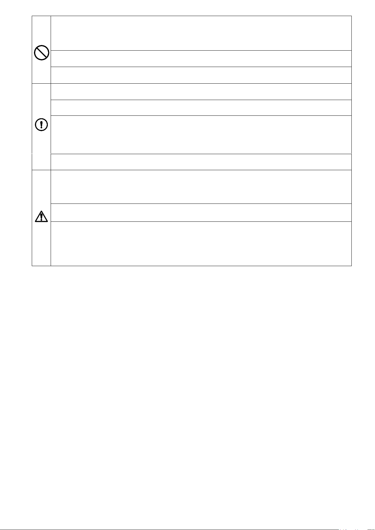
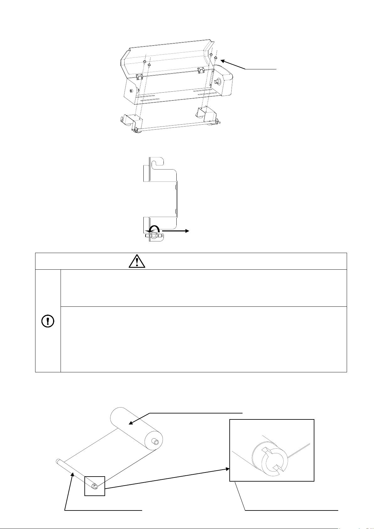
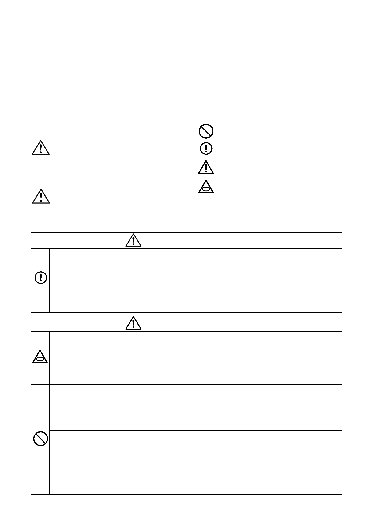
本体回転部に指や異物を入れないでください。
本製品の取付けやフィルタ交換は、製品の動作を停止させてから行ってください。
→ケガの原因になります。
Do not put your fingers or foreign substances into the rotating part.
Installation and filter replacement work should be done after stopping operation of the product.
Failure to the above can lead to injury.
引火性ガス、腐食性ガス、油煙、絶縁を悪くするチリ等が発生または充満する場所では使用できません。
→発火、寿命の低下、損傷の原因になります。
This product should not be used where inflammable gas, corrosive gas, oil fumes or dust which may affect
insulation are contained in the air.
Failure to this may result in short life or damage of the unit.
火気、火の粉、火花が発生する場所では使用しないでください。
→火災の原因になります。
For prevention of fire accidents, do not use this product in a place where fire or sparks generates.
多量のオイルミスト、液体、蒸気が発生する場所では使用できません。
→故障の原因になります。
Do not use this product in a place where large amount of oil mist, liquid and/or steam generates.
Failure to this can lead to breakdown of the product.
絶対にしてはいけない「禁止」を意味します。
Prohibited matters that should never be done.
必ず実施していただく「強制」を意味します。
Matters that must be carried out.
気をつけていただく「注意喚起」を意味します。
Matters to which due attention should be paid.
「回転物注意」を意味します。
Caution for rotating devices.

- 3-
運搬および取付時は衝撃・振動は加えないでください。
→寿命の低下、異音・破損の原因になります。
Impacts and vibrations should be avoided during transportation and installation of this product.
Failure to this can be a cause of short life, abnormal noise and breakdown of the product.
振動・衝撃等のある場所では、使用できません。
The site of use should be free from stress such as vibration or impacts.
屋外及び高度 1000m 以上の場所での使用はできません。
This product is not designed for using outdoor or at highland over 1000 meter altitude.
動作温度範囲・動作湿度範囲内で必ず使用してください。
Use this product within the temperature and humidity range specified herein.
保管する時は、周囲温度が+50℃以下の環境で保管してください。
Storage temperature should not exceed 50℃.
配置には、電気工事が必要です。専門業者にて設置してください。
→配線等の設置工事に不備があると、感電や火災の原因になります。
Electrical works required for installation of the product must be done only by specialists.
Improper installation may result in electrical shocks or fires.
本製品が納入された時、その梱包状態が損傷していないことを確認してください。
Make sure that there is no damage on the package on delivery.
この取扱説明書の内容を全て読み、正しい方法で使用してください。
正しい方法で使用されない場合は、機器の持つ保護性能が損なわれ、事故、破損の原因となります。
Please read all the contents of this manual for proper usage. Improper usage can damage protection
performance and lead to an accident or breakage of the product.
本体の改造・修理は絶対にしないでください。また、修理をする場合はメーカにご相談ください。
Never tamper or repair the unit by yourself. Please consult your local supplier for repairing.
マグネットステーを磁気カードなどの磁気記録媒体に近づけると、データが破壊されて使用できなくなる恐れ
があります。また、精密電子機器に近づけると故障の原因になる恐れがあります。
To avoid the risk of destruction of data stored in magnetic cards and other magnetic media, keep the Magnet
Stay away from those media. Also, it should not be placed nearby precision electronic equipment to avoid
the risk of breakdown of the equipment.

- 4-
■各部の名称 Part names
フィルタケース
Filter case
マグネットステー [別売]
Magnet Stay [Option]
巻取りケース
Winding case
巻取りケース(背面)
Winding case (rear view)
フィルタ
Filter
操作パネル
Operation panel
制御部
Control part
巻取りユニット
Winding unit
ヒューズホルダー
Fuse holder
250V 2A
主電源スイッチ
Main power switch
電源ケーブル
Power cable
長穴
Slot
クランプステー [別売]
Clamp Stay [Option]
ノブ
Knob
ゴムパッド
Rubber pad
マグネット
Magnet
フィルタガイド
Filter guide
フィルタガイド
Filter guide

- 5-
■設置 Installation
注意 Caution
本製品の使用電源は必ず銘板に表記してある指定定格電圧を
使用してください。また、本製品への電源取入れ口には、必ず適
切なブレーカを介して接続し、漏電による感電防止のため、アー
ス線は必ず接地してください。
The supply voltage must be as specified on the rating plate of the
product.
Electrical connection should be made via appropriate circuit breakers
as shown in the right.
Ground the wire without fail to prevent electrical shocks
設置には電気工事が必要です。専門業者にご相談ください。
→配線等の設置工事に不備があると感電や火災の原因となります。
Electric works for installation of KURU KURU FILTER should be done
by professionals. Faulty wiring may lead to electrical shocks or fire
accident.
フィルタ交換が出来るように空間を確保してください。(p.38 外形寸法図参照)
→フィルタ交換が出来ない場合があります。
Leave a space necessary for filter replacement. (See page 38)
マグネットステーによる設置を行う際には、必ず取付面への吸着力を確認してください。
吸着力が弱い場合フィルタケースまたは、巻取りケースが脱落する恐れがあります。
When installing the product using the optional Magnet Stay, ensure its sticking power to the mounting surface
without fail. If the sticking power is not enough, the Filter Case or the Winding Case may fall.
本製品を設置する際は必ずクランプステーおよびマグネットステーを使用してください。脱落の恐れがあります。
For installation, be sure to use either the optional Clamp Stay or Magnet Stay. Failure to this can lead to falling
accident of the product.
フィルタケースと巻取りケースの距離が 700mm 以上の場合、フィルタ交換警告(p.28 参照)が表示しないことが
あります。その場合は巻取り不良警告(p.28 参照)が表示されます。フィルタケースと巻取りケースの設置時には
ご注意ください。
In case the distance between the Filter case the Winding part is over 700mm, the filter replacement alarm may
not work. In this case, winding error alarm is indicated instead. See page 28 for the alarms.
1.設置方法組合せ Combination of installation method
本製品を取付ける際、クランプステーのみでの取付け、マグネットステーのみでの取付け、クランプステーとマグ
ネットステーを組合せた取付けが可能です。以下の図に設置方法の組合せとカバーの開閉方向を示します。
This product can be fitted in different combinations of fitting tools, such as with using Clamp Stays only, Magnet
Stays only or both of Clamp Stay and Magnet Stay. The following illustrations show the variation of fitting method
and cover opening/closing directions.
設置 A上側:フィルタケースをクランプステーにより固定
下側:巻取りケースをクランプステーにより固定
AUpper side : Filter case is fitted with Clamp Stay
Lower side : Winding case is fitted with Clamp Stay
アース
Earth
過電流
ブレー
カ
Overcurre
nt breaker
クランプステー
Clamp Stay
OKF-CS※※※-01
クランプステー
Clamp Stay
OKF-CS※※※-01
過電流ブレーカ
Overcurrent breaker
過電流ブレーカ
Overcurrent breaker
漏電ブレーカ
Earth leakage breaker
漏電ブレーカ
Earth leakage breaker

- 6-
設置 B上側:巻取りケースをマグネットステーにより固定
下側:フィルタケースをマグネットステーにより固定
B Upper side : Winding case is fitted with Magnet Stay
Lower side : Filter case is fitted with Magnet Stay
設置 C上側:フィルタケースをマグネットステーにより固定
下側:巻取りケースをクランプステーにより固定
CUpper side : Filter case is fitted with Magnet Stay
Lower side : Winding case is fitted with Clamp Stay
設置 D上側:巻取りケースをマグネットステーにより固定
下側:フィルタケースをクランプステーにより固定
D Upper side : Winding case is fitted with Magnet Stay
Lower side : Filter case is fitted with Clamp Stay
マグネットステー
Magnet Stay
OKF-MS01
マグネットステー
Magnet Stay
OKF-MS01
クランプステー
Clamp Stay
OKF-CS※※※-01
クランプステーClamp
Stay
OKF-CS※※※-01
マグネットステー
Magnet Stay
OKF-MS01
マグネットステー
Magnet Stay
OKF-MS01

- 7-
2.設置空間の確認 Check the installation space
取付対象物の周囲に干渉物がある場合、本製品を設置できないことがあります。
本体を設置する際、取付対象物に対するフィルタの設置箇所によっては、下図に示す範囲に巻取りケース設置
のための空間が必要になる可能性があります。
この範囲に干渉物がないことを確認してください。
In case interference objects exit, the product may not be fitted properly.
Depending on the location to which the product is fitted, the minimum space shown in the following illustration
can be required. Please make sure that no interference object exists within this area.
本体を設置する際、巻取りケースはフィルタの幅に対して左側約 40mm 右側約80mm の範囲を必要とします。
そのため、フィルタから左 40mm 右80mm の範囲に干渉物がある場合取付けられないことがあります。
As illustrated, the Winding Case protrudes from the filter by approx. 40mm on right side and approx. 80mm on left
side. Any physical interference within it may prevent the product from being fitted properly.
3.フィルタケース、巻取りケースの設置 Installation of Filter case and Winding part
(1) 設置方向 Mounting direction
下図の【良い例】に沿って設置方向を決めてください。【悪い例】のように設置すると制御部に油が侵入し、故障す
る恐れがあります。
Select the mounting direction according to the following good examples. If the product is mounted as shown in the
bad examples, product failure can occur.
取付対象物
(上面)
Installed object
(Top surface)
取付に必要な
取付対象物前面の空間
(取付対象物上部より見た図)
Requisite space on front of the
installed object
(View from the top)
フィルタに対する巻取りケースサイズ
Protrusion of Winding Case from filter
フィルタ
Filter
良い例
Good examples
悪い例
Bad examples

- 8-
(2) クランプステーの設置方法 Mounting with Clamp Stay
取付可能製品幅 Mountable product width
①クランプステーのゴムパッドが接触する面を、油や汚れが残らないように洗浄してください。油や汚れが設置
面に付着した状態でクランプステーを設置すると、脱落の原因になります。
Clean oil and dirt off the surface on which the rubber pad of Clamp Stay touches. The Clamp Stay may drop
if the surface is not cleaned.
②ノブを反時計回りに回転させるとクランプステーの幅を広げることができます。クランプステーを取付ける際に
は取付ける対象物の大きさに合わせ、ゴムパッドの間隔を広げてください。
By turning the knob counterclockwise, Clamp Stay is extended in width. For attaching Clamp Stay, adjust its
width to fit the size of installed objects.
※クランプステーが広がりきったところからさらにノブを回転させると、ノブがクランプステーから脱落する恐
れがあります。回しすぎに注意してください。
If the knob is turned too much, it can drop off from the Clamp Stay.
③クランプステーを取付面に合わせ、両側のゴムパッドが取付面に接触するまでクランプステーの幅を
狭めてください。
Position the Clamp Stay on the mounting surface and slide the both ends until the rubber pads on both ends
touch the mounting surface.
くるくるフィルター型式
KURU KURU FILTER model
取付け可能製品幅
Range of mountable width
OKF-AOC320-AW
350mm~390mm
OKF-AOC430-AW
460mm~500mm
OKF-AOC520-AW
550mm~590mm
ゴムパッド
Rubber pad
取付面
Mounting
surface
ゴムパッド
Rubber pad

- 9-
④ノブ内側がクランプステーに接触するまで回転させてください。ノブ内側がクランプステーと接触したところか
ら約8回転時計回りに締めこんでください。
ノブを回転させ締めこむ際には規定値以上の回転数でノブを締めこまないでください。
※0.8Nm (8.2kgf・cm)以上の力で締めこんだ場合、クランプステーが破損する恐れがあります。
Turn the knob clockwise until its inner side touches the side plate of the Clamp Stay. Then, secure the Clamp
Stay by making another 8 turns or around. Pay attention not to tighten the knob with 0.8Nm (8.2kgf・cm) or
more torque.
*Excessive tightening torque may destroy the Clamp Stay.
⑤フィルタケースまたは巻取りケースを付属のM4ネジで固定してください。固定の際に p.5 の設置方法組合せ
を参照し、フィルタケース、および巻取りケースの取付ける向きに注意してください。
Fix the Filter Case or the Winding Case using the provided M4 screws. Pay attention to the mounting direction
of it referring to “1. Different combinations of fittings” in the paragraph “Installation” in page 5.
(3) マグネットステーの設置方法 Mounting with Magnet Stay
①マグネットステーを設置する面に油や汚れが残らないよう洗浄してください。油や汚れが設置面に付着した状
態でマグネットステーを設置すると脱落の原因になります。
Remove dirt and oil from the mounting surface using a cleaning agent. If oil remains, magnet cannot stick
firmly to the surface and the product may fall.
②本体付属のアルミパイプへ、マグネットステーに固定された蝶ネジを挿入してください。
Insert the wing screw attached to the product into the aluminum pipe supplied.
ノブ内側がクランプステーに接触
したところから約8回転させます。
※0.8Nm(8.2kgf・cm)以上の力で
締めこまないでください。
Turn the knob about 8 times after
it touched the Clamp Stay
surface.
*Do not tighten the knob with
0.8Nm(8.2kgf・cm) or more torque.
ノブの位置は正面から見て右、
左どちらでも取付け可能です。
The knob can be placed either
side.
M4 ネジ
M4 screw
p.4 の設置方法組合せを参照しカ
バーが開く向きに注意してくださ
い。
See “1. Different combinations of
fittings” in page 4 to check which
way the cover opens.

- 10 -
③マグネットステーと巻取りケースおよび、フィルタケースを本体付属の M4 ネジで固定してください。
Fix the Magnet Stay, the Winding Case and the Filter Case with the M4 screws attached.
④両側の蝶ネジと角ナットを緩めアルミパイプを取外してください。
Loosen the wing screws and the square nuts on both sides to remove the aluminum pipe.
4.フィルタの取付け Fitting of filter
注意 Caution
巻取りユニット側の回転軸を外部からの力によって、強制的に回転させないでください。
→モータの故障の原因となります。
Do not rotate the rotary axis of motor forcibly by external force.
→Failure to this can result in breakdown of the motor.
純正フィルタが装着されている場合は、取外してから本製品を取付けてください。
フィルタを二重にした状態で使用しないでください。
→取付対象物の性能低下や故障の原因となります。
In case the installed object has been fitted with its manufacturer's original filter, be sure
to remove it before installing this product.
Do not use this product placing it over the existing filter.
→Failure to this can lead to decline in performance and/or breakdown of the installed object.
フィルタが巻かれている方をフィルタケース側へ、フィルタの軸に切込みが入っている方を巻取りケース側へ取り付
けてください。
Fit the filter rill in the Filter case and the precut filter core in the Winding part.
M4 ネジ
M4 screw
フィルタケース側 To Filter case
切込み拡大図
Expanded view of the slits
巻取り側 To Winding part

- 11 -
(1) 設置 Aによるフィルタ取付方法
Filter installation by installation type A
①フィルタを設置したい吸気口の上下にクランプステーを設置し
てください。純正フィルタが装着されている場合、純正フィルタ
を取外し、その開口部上下に p.8 のクランプステー設置方法を
参照しクランプステーを固定してください。
Position the Clamp Stays on the top and bottom of the suction
port to which filter is set. In case anther filter has already
been there, remove it. Then, fix the Clamp Stays
referring to “(2)Mounting with Clamp Stay” in page 8.
②上のクランプステーにフィルタケース、下のクランプステーに巻取りケースを、カバーの開閉方向に注意し取
付けてください。取付ける際フィルタケースと巻取りケースの左側面が同じ位置になるよう調整してください。
Attach the Filter Case on the upper Clamp Stay and the Winding Case on the lower Clamp Stay paying
attention to opening/closing direction of the covers. Align the left sides of the Filter Case and the Winding
Case when attaching them.
③クランプステーに取付けられている、蝶ネジと角ナットを取外してください。
Remove the wing screw and the square nut from the Clamp Stay.
④本体付属のフィルタガイド用アルミパイプを設置します。
アルミパイプをクランプステー内側へ固定するため、クランプステー側面の角穴から角ナットが取付いた蝶ネ
ジを挿入しアルミパイプへ差し込んでください。
※フィルタケース側のクランプステーは上側に取付け、巻取りケース側のクランプステーは下側に取付けてく
ださい。
Attach the provided aluminum filter guide pipe.
To fix the pipe inside the Clamp Stay, insert the wing screw with attaching the square nut into the pipe
through one of the two square holes of the Clamp Stay.
Note : Use the upper square hole of the Clamp Stay for Filter Case side and the lower square hole of the
Clamp Stay for the Winding case for fixation.
角ナットをゆるめ 2mm 程度
開けてください。
Loosen the square nut to
leave a space of about 2 mm.
角ナット
Square nut
蝶ネジ
Wing screw
下側:巻取りケース+クランプステー
Lower side : Winding case
上側:フィルタケース+クランプステー
Upper side : Winding case
揃えてください
Align the sides
ノブの位置は正面から見て右、
左どちらでも取付け可能です。
Knob can be positioned on
either side.

- 12 -
⑤下図の向きにフィルタケース内の両側のホルダーにフィルタの軸を嵌め込んで固定してください。
Fit the filter core into the holders on both ends in the Filter Case in the direction as shown below.
フィルタケースは正
面から見て上に、巻
取りケースは正面
から見て下に、蝶ネ
ジと角ナットを取付
ける。
Fix the Filter Case
upper side and the
Winding Case lower
side with respective
wing screws and
square nuts.
アルミパイプ
Aluminum pipe
取付けたら手前で仮固定
してください。
Temporarily fix the wing
screw on the near side.

- 13 -
⑥フィルタをアルミパイプの奥を通してください。アルミパイプの奥を通す際にフィルタの送り出しが奥側になるよ
うに注意してください。
巻取り側の軸の切り欠きが巻取りユニット側にくるように通してください。
⑦フィルタの軸をローラーに合わせて、矢印の方向へ押し込んでください。
Align the filter core on the roller and push it to the arrowed direction.
⑧フィルタを押し込んだまま、回転軸にフィルタの軸を合わせて挿し込んでください。
With holding the filter core down on the roller, align its slits on the rotary core on the other end to set in.
アルミパイプ
Aluminum pipe
切込みを合わせる
Align the slits on the rotary axis
フィルタ軸 Filter core
断面図
Cross section
ローラー Roller
※センサー等がある場合はセンサ
ーと開口部との間にフィルタを通す
ようにしてください。
*If there is a sensor and the like
above the suction port, pass the
filter in between.
フィルタの送り出しの方向に注意してください。
Pay attention to the feed direction of filter.
2箇所
回転軸 Rotary axis

- 14 -
⑨仮固定していた蝶ネジを緩め、アルミパイプを奥に移動させ固定し、フィルタが正しくセットされているか確認
してください。
Loosen the temporarily fixed wing screw and move the aluminum pipe backward. Make sure the filter is set
appropriately.
⑩フィルタが巻取りケースに対して、真っすぐになっていることを確認してください。真っすぐになっていない
場合、巻取りケースまたはフィルタケースを固定している M4 ネジを緩め、左右にずらし真っすぐになるよう調
整してください。
Make sure that the filter is not inclined. If not, loosen the M4 screw of either of the Winding Case or the Filter
Case to adjust its position so the filter can go straight.
フィルタがアルミパイプの奥を通って
いることを確認してください。
Make sure that the filter is routed
around the outside of the aluminum
pipes.
アルミパイプ
aluminum pipe

- 15 -
(2) 設置 Bによるフィルタ取付方法
Filter installation by installation type B
①フィルタを設置したい吸気口の上側にマグネットステーで取付いた巻取りケース、下側にマグネットステーで取
付いたフィルタケースを取付けてください。純正フィルタが装着されている場合、純正フィルタを取外してくださ
い。マグネットステーの設置については p.9 を参照してください。
Attach the Winding Case with the Magnet Stay on the upper side and the Filter Case with the Magnet Stay on
the lower side of the suction port. In case anther filter has already been there, remove it. For attaching to the
Magnet Stays, see page 9.
②下図の向きにフィルタケース内の両側のホルダーにフィルタの軸を嵌め込んで固定してください。
Fit the filter core into the holders on both ends in the Filter Case in the direction as shown below.
③フィルタの軸を巻取りケースのローラーにあわせて、矢印の方向へ押し込んでください。
Align the filter core on the roller and push it to the arrowed direction.
上側:巻取りケース+マグネットステー
Upper side : Winding case+Magnet Stay
下側:フィルタケース+マグネットステー
Lower side : Filter case+Magnet Stay
断面図
Cross section
フィルタ軸 Filter core
ローラー Roller

- 16 -
④フィルタ軸の切込みを巻取りケースの回転軸に合わせ下図の向きになるようにセットしてください。
Align the slits of filter core with the rotary axis of Winding Case and set the filter so it is directed as illustrated
below.
※センサー等がある場合はセンサー
と開口部との間にフィルタを通すよう
にしてください。
*If there is a sensor and the like
above the suction port, pass the filter
in between.
巻取りケース
Winding case
フィルタケース
Filter case
回転軸 Rotary axis
切込みを合わせる
Align the slits on the rotary axis

- 17 -
⑤本体付属のフィルタガイド用アルミパイプを設置します。
蝶ネジと角ナットが組み付いた状態のアルミパイプを、フィルタに押し当てながらマグネットステーの切り欠き
にかけ、蝶ネジを固定してください。
Install the provided aluminum filter guide pipe.
Hook the wing screw and square nut-attached pipe on the slits of Magnet Stay with pressing against the filter
and secure the wing screw.
アルミパイプ
Aluminum pipe
アルミパイプを奥まで移動
させ矢印の方向に下 げ固
定する。
Move the aluminum pipe
backward and then
downward to secure.
フィルタがアルミパイプの奥を通っている
ことを確認してください。
Make sure that the filter is routed around
the outside of the aluminum pipes.
モータ回転方向
Direction of motor rotation

- 18 -
⑥フィルタが巻取りケースに対して、真っすぐになっていることを確認してください。真っすぐになっていない
場合、巻取りケースまたはフィルタケースを固定している M4 ネジを緩め、左右にずらし真っすぐになるよう調
整してください。
Make sure that the filter is not inclined. If not, loosen the M4 screw of either of the Winding Case or the Filter
Case to adjust its position so the filter can go straight.
(3) 設置 Cによるフィルタ取付方法
Filter installation by installation type C
①フィルタを設置したい吸気口の上側にフィルタケースがとりついたマグネットステーを、下側に巻取りケースが
取付いたクランプステーを設置してください。純正フィルタが装着されている場合、純正フィルタを取外してくだ
さい。設置方法は p.8~p.10 のクランプステーの設置方法およびマグネットステーの設置方法を参照してくだ
さい。
Attach the Filter Case with the Magnet Stay on the upper side and the Winding Case with the Clamp Stay on
the lower side of the suction port. In case anther filter has already been there, remove it. For attaching to the
Clamp/Magnet Stays, see page 8 to 10.
②クランプステーに取付けられている蝶ネジと角ナットを取外してください。
Remove the wing screw and the square nut from the Clamp Stay.
上側:フィルタケース+マグネット
Upper side : Filter Case+Magnet Stay
下側:巻取りケース+クランプステー
Lower side : Winding case+Clamp Stay

- 19 -
③p.11 の工程④を参照し、クランプステーへ本体付属のフィルタガイド用アルミパイプを設置します。
アルミパイプをクランプステー内側へ固定するため、クランプステー側面の角穴から角ナットが取付いた蝶ネ
ジを挿入し
アルミパイプへ差し込んでください。
Attach the aluminum filter guide pipe on the Clamp Stay referring to the procedures described in page 10.
To fix the pipe inside the Clamp Stay, insert the wing screw with attaching the square nut into the pipe
through one of the two square holes of the Clamp Stay.
④下図の向きにフィルタケース内の両側のホルダーにフィルタの軸を嵌め込んで固定してください。
Fit the filter core into the holders on both ends in the Filter Case in the direction as shown below.
⑤フィルタ軸をアルミパイプの奥を通し、巻取り側に持ってきてください。
Bring the filter core through the back of the aluminum pipe to the winding side.
アルミパイプ
Aluminum pipe
フィルタ軸
Filter core
巻取りケース
Winding case
フィルタケース
Filter case
取付けたら手前で
仮固定してください。
Temporarily fix the
wing screw on the
near side.

- 20 -
⑥フィルタの軸を巻取りケースのローラーにあわせて、矢印の方向へ押し込んでください。
Align the filter core on the roller and push it to the arrowed direction.
⑦フィルタ軸の切込みを巻取りケースの回転軸に合わせ下図の向きになるようにセットしてください。
Align the slits of filter core with the rotary axis of Winding Case and set the filter so it is directed as illustrated
below.
ローラー Roller
フィルタ軸 Filter core
断面図
Cross section
※センサー等がある場合はセンサーと開口部
との間にフィルタを通すようにしてください。
*If there is a sensor and the like above the
suction port, pass the filter in between.
回転軸 Rotary axis
切込みを合わせる
Align the slits on the rotary axis
This manual suits for next models
2
Table of contents
Popular Water Filtration System manuals by other brands

OptiPure
OptiPure FX-21 Installation, operation & maintanance manual

Oase
Oase Filtoclear 3000 operating instructions

Daikin
Daikin EKAFV100F Series installation manual

Franklin Water Treatment
Franklin Water Treatment PKLX Series Installation instructions and owner's manual

koller
koller ASZEP10-PL instructions

Zodiac
Zodiac TRi Series Instructions for installation and use

Netafim
Netafim Arkal 2" Spin-Klin Compact Stand Alone... Installation and operation instructions

Parker
Parker F55 Series Installation & service instructions

Siemens
Siemens SINAMICS G130 operating instructions

Whole House
Whole House KDF/GAC Assembly instructions

Philips
Philips Pure Taste WP3861 manual

JRC
JRC NSVS1203 manual