Okayo EJ-600DR User manual

Digital Dual-channel
Diversity Microphone System
User Manual

Notice: The changes or modifications not expressly approved by the party responsible for compliance could void the
user's authority to operate the equipment.
FCC INFORMATION
The Federal Communication Commission Radio Frequency Interference Statement includes the following paragraph:
-- Reorient or relocate the receiving antenna.
-- Increase the separation between the equipment and receiver.
-- Connect the equipment into an outlet on a circuit different from that to which the receiver is connected.
-- Consult the dealer or an experienced radio/TV technician for help.
The equipment has been tested and found to comply with the limits for a Class B Digital Device, pursuant to part 15
of the FCC Rules.
These limits are designed to provide reasonable protection against harmful interference in a residential installation.
This equipment generates, uses and can radiate radio frequency energy and, if not installed and used in accordance
with the instruction, may cause harmful interference to radio communication.
However, there is no grantee that interference will not occur in a particular installation. If this equipment dose cause
harmful interference to radio or television reception, which can be determined by turning the equipment off and on,
the user is encouraged to try to correct the interference by one or more of the following measures:
IMPORTANT NOTE: To comply with the FCC RF exposure compliance requirements, no change to the antenna
or the device is permitted. Any change to the antenna or the device could result in the device exceeding the
RF exposure requirements and void user's authority to operate the device.
This device complies with part 15 of the FCC Rules.
Operation is subject to the following two conditions: (1) This device may not cause harmful interference, and
(2) this device must accept any interference received, including interference that may cause undesired operation.
Illustration ...........................................
Setup Procedure ......................................................................................... 2
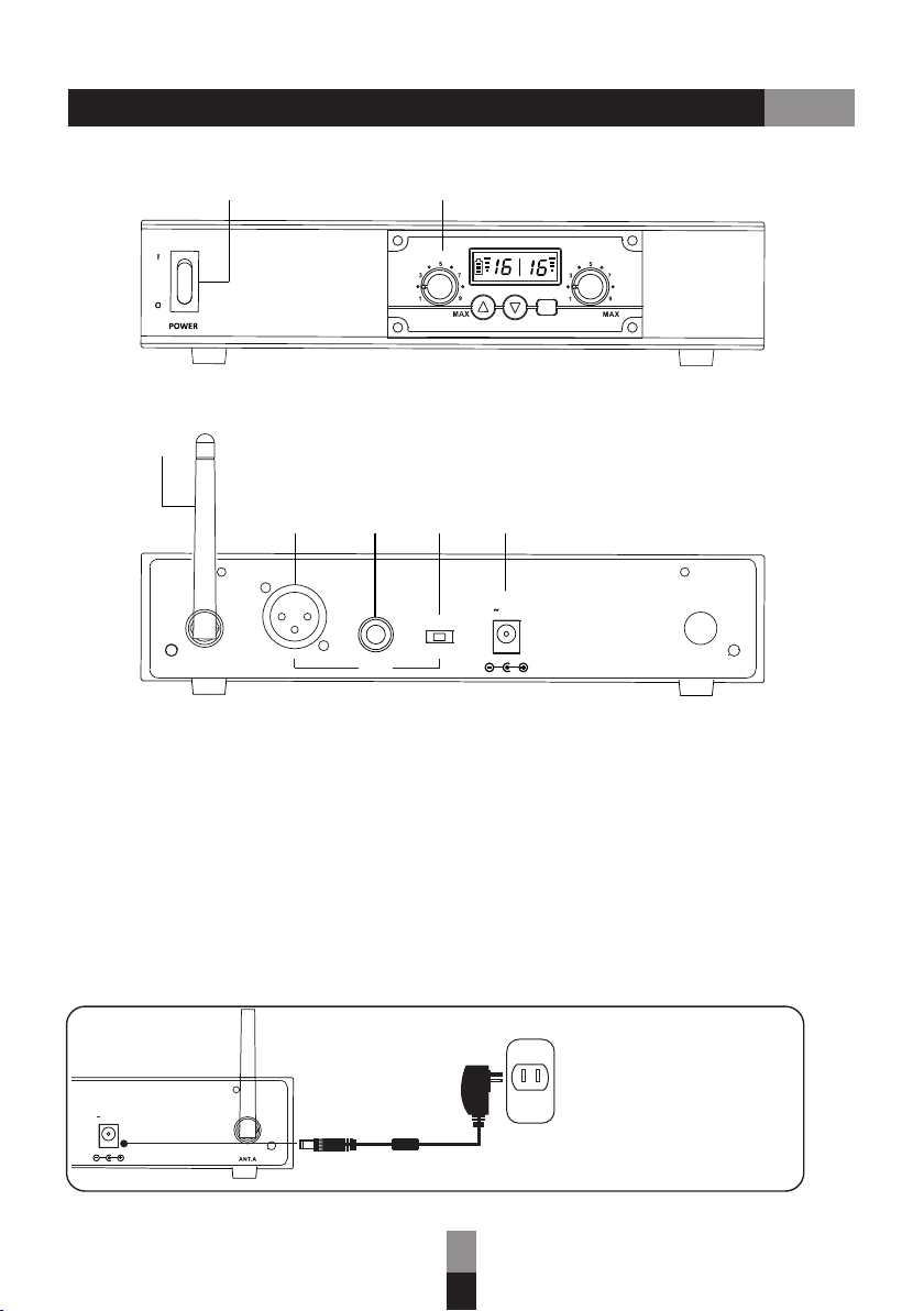
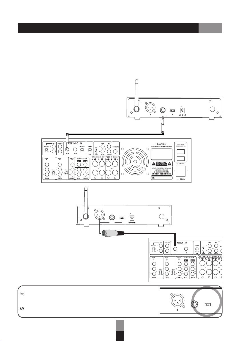
Digital Wireless Receiver Module ............................................................ 3 ~ 4
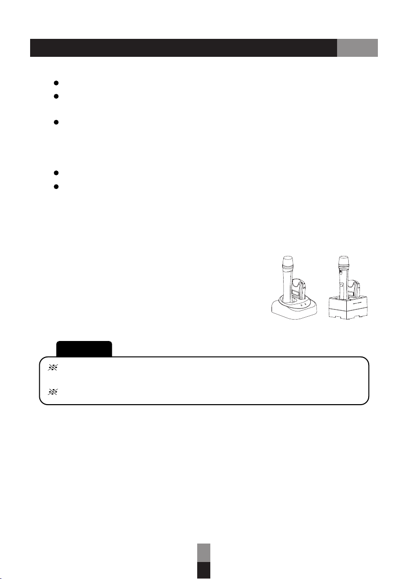
Digital Handheld Microphone ................................................................ 5 ~ 7
Digital Pendant/Bodypack Transmitter ................................................... 8 ~ 10
Important Notes / Troubleshooting .............................................................. 11
Specifications ...................................................................................... 12 ~ 13
............................................. ....... 1
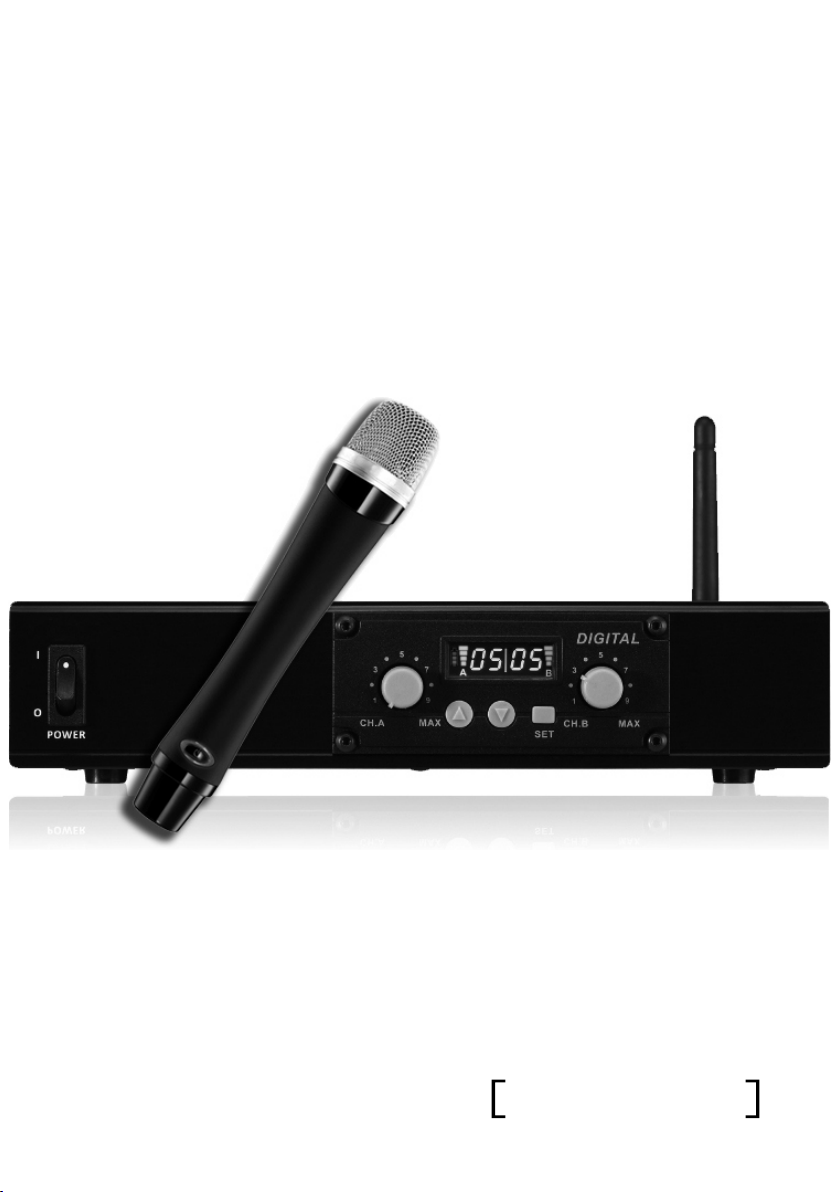
Thank you for the purchase of Digital Dual-channel Diversity Microphone System.
This manual will give comprehensive instructions and operation.
Please read it over before your use to perform this unit well.
Preface
Contents
Contents

12
SET
DIGITAL
CH .A CH .B
B
A
ANT AF OUT
LOW/HI
DC INPUT
12 15V/1A
4 5 6 7
3
1
DC INPUT
12 15V/0.6A
1. Power Switch
2. Receiver Module Digital Wireless
3. Antennas
4. Balanced AF XLR Output
5. Unbalanced AF Output (6.3 mm jack)
6. AF Impedance Selection (for 5)
7. DC Power Socket
Power Supply
Please use our product
AC Switching Adaptor as
attached.
‘s
Illustration

ANT A F OUT
LOW/HI
DC IN PUT
12 15 V/1A
2
AF OUT
LOW/H I
Setup Procedure
Signal Connections
1. Connect 6.3 mm mic jack from Unbalanced AF Output to amplifier s MIC IN
and set “impedance” at “LOW”. Or connect 6.3 mm mic jack from “unbalanced
AF Output” to amplifier’s “LINE IN” and set “impedance” at “HI”. (The same
way can be applied in Single-channel Diversity Receiver / Dual-channel Receiver.)
“ ” ’ “ ”
Amplifier
2. If using XLR mic jack connect it from
”Balanced AF Output” to amplifier’s “AUX IN”.
,
In order to prevent from the impedance from being too high thus producing
unexpected noise, please set “impedance” at "LOW” if you are connecting
a mic jack to a “low input” in the subordinate device.
If your subordinate device is with general input socket (e.g., LINE IN, AUX IN
, etc), please set ”impedance” at “HI” to avoid too low volume output - .
AF Impedance Selection (HI / LOW Control)
Remark: AF Impedance Selection only controls
Unbalanced AF Output (6.3 mm jack).
ANT A F OUT
LOW/HI
DC IN PUT
12 15 V/1A

3
SET
DIGITAL
CH.A CH.B
15
4
3
2
B
A
Digital Wireless Receiver Module
1. LCD display
(channel number/
signal strength/
A channel battery meter)
2. A channel volume
3. Channel selection
4. Set key
5. B channel volume
Operation
Power on and Off
1. Receiver module powers on along with the PA LCD displays On and after
to 2 seconds, screen displays channel number.
, , 1
2. Receiver module powers off along with the PA, LCD displays Off, after 2 to 3
seconds the display shuts off.
Channel changing
1. Hold on SET key to enter channel changing mode, once the channel number on
the display starts to flash, you may use the up and down key to select channel.
2. After confirm the channel, press SET key again, or it also auto confirms without
pressing any keys for less than 10 seconds.
Operating range Hi/Low setting
1. In off mode, press SET key and power on the PA to enter the setting mode.
2. Now the screen flashes Hi or Lo, press up and down key to switch in between.
3. Press SET key again to confirm, or it also auto confirms without pressing any
keys for less than 5 seconds.

4
a. When both microphones are set as Master:
b. When the microphones are assigned as Master and Slave:
Setting channel synchronization
1. First powered on microphone will be set as channel A, and the second is
channel B.
2. When channel A microphone is shut off or out of signal for more than 5
seconds, B channel microphone auto switches to channel A.
3. Both channels A and B need to be within the range of meters when
power on.
15
1. Preset Master microphone will be identifying as channel A and the slave
will be channel B.
,
2. When channel A microphone is shut off or out of signal for more than 5
seconds, B channel microphone auto shuts off.
3. Only when microphone is set to salve and push to talk mode, the
synchronization is at full range. The other modes are set within 15 meters.
Digital Wireless Receiver Module

5
A
12345
611
10
9
8
7
1. Mesh head
2. Handheld tube
3. Power indicator
4. Power button
5. LCD display
6. setup wheel
(Press to set, scroll up and down to adjust)
7. Talk/Mute button
8. Battery holder
9. Battery door
10. Maser/Slave mode switch
11. Charging contacts
Insert battery
Open battery door and insert 2 AA 1.2 V (Ni-MH 1600mAh)
or 2 AA 1.5 V Alkaline batteries. Make sure the batteries are
allocated in correct direction.
Digital Handheld Microphone

6
Under Talk mode:" ”
Under mode:"Push”
Handheld method
Do not block bottom signal source.
Operation and Setup
Power On
Insert battery and press power button to turn on, power indicator (3) lights on.
Blue light means battery power is efficient and red means insufficient.
Press setup wheel (6) then scroll up and down to adjust volume.
Green microphone icon - Talk Red microphone icon Mute ; -
Green microphone icon - Talk Flashing red microphone icon Mute; -
Volume adjustment
Master/Slave mode setup
When set to Slave mode, the default channel will be B CH, and it will
always stay in B CH.
After battery is taken off, you can see master/slave mode switch(10).
When set to Master mode, the default channel will be A CH, when A CH is
occupied, the channel will switch to B CH
Push Talk mode
1. Press mute (7) to talk.
2. Let go mute (7) to mute.
3. It does not support more than 3 microphones.
Digital Handheld Microphone

7
Power Off
Charging
Channel synchronization
Charger Charger
Hold on to power key (4) for more than seconds to shut off. 2
You may charge the microphone with rechargeable
batteries by cherger(purchase separately).
The microphone will automatically sync when powered on.
When syncing successfully, mute key lights in blue and channel number shows.
If syncing failed, then mute key lights in red and no channel number display.
When microphone is set to slave mode:
Requires within 15 meters.
If idle more than 30mins, then microphones shuts off.
1. B CH only functions when A CH exists
2. When A CH is in use, you will not be able to talk
3. When A CH gets shut down, B CH also automatically shuts down.
.
.
CAUTION!!
Take out batteries when the devices won’t be operated in a long time.
DO NOT attempt to charge Alkaline battery. It will lead to battery
leakage or even explosion!
Digital Handheld Microphone

8
6
7
5. Charging indicator
6. Neck strap hole
7. DC input
8. Strap hole
9. Belt clip.
10. Mic in
11. AUX in
12. Charging terminal
10 11
8
9
12
1
2
3
4
5
1. Power/Mute switch
2. Volume control
3. LCD window
4. Mesh Head
Operation and Setup
Power ON
1. Press power key (1) to power on.
2. Once powered on, the channel selection blinks and standby for pairing.
Once paired successfully, battery meter, channel number and Ch A or Ch B
display on the screen
. .
.
3.
shuts off.
When the device idle more than 30 minutes without paring, the device
Digital Pendant/Bodypack Transmitter

9
Mute / Talk switch
Channel synchronization
Power OFF
1. Press and hold for two seconds to turn the device off.
2. OFF display on screen and all indicators turned off.
Charging mode
1. LED lights red when charging.
2. LED lights green when battery is fully charged.
3. When device is slot into a charger stand, will off the power.
4. Battery error: LED status lights red and flashes when charging,
LCD battery symbol lights flashes, and it caused by:
(1)The battery charge temperature is exceeded 60 C.
(2)The duration of charging time for charger stand is exceeded
seven hours.
(3)The battery is defected.
o
1. Press Mute switch (1) to switch between mute and talk mode.
2. Talk mode lights in blue and mute mode lights in red.
The pendant microphone will automatically sync when powered on.
When syncing successfully, mute key lights in blue and channel number shows.
If syncing failed, then mute key lights in red and no channel number display.
When microphone is set to slave mode:
1. B CH only functions when A CH exists.
2. When A CH is in use, you will not be able to talk.
3. When A CH gets shut down, B CH also automatically shuts down.
Requires within 15 meters
If idle more than 30mins, then microphones shut off.
Master/Slave mode
1. When the device is turned off, press SET key (2) then power key (1) to enter
set up mode.
2. When the screen blinks with Master or Slave press or o
switch mode.
“ ” “ ”, (2) t
3. Press SET (2) to confirm and exit or it auto confirms within 5 seconds.
Digital Pendant/Bodypack Transmitter

10
LCD screen will display current used volume level when press or
(VOL. 1 ~ 3).
Press and then press power key to power on to enter RESET mode. (2) (1)
The default value is Volume 2, and Master/Slave does not affect by RESET mode.
Volume switch
Reset
Method to install neck strap
The best distance is 10 CM between pendant microphone and user s chin.’
CAUTION!!
To maintain battery life, please charge fully after use every time,
or every 3 months.
If battery require replacement, please pass to
to do so.
professional technician
Digital Pendant/Bodypack Transmitter

11
Keep the device away from any heat source and in a
Do not leave it under sunlight or close to heater.
location with good ventilation.
DON’T operate the device in the rain or in humid circumstance to prevent failure.
Prevent the device from dropping.
Apply factory recommended power supply to this system only. It is dangerous and
risky when employing a unqualified power.
Troubleshooting
Failed to Power On
Be sure batteries are allocated and put in correct direction.
Be sure power adapter is plugged well.
No Sound Output
Be sure Mute button is not on.
Check if there is huge air interference nearby.
Be sure volume control on transmitter and receiver are turned properly.
Be sure transmitter and receiver stay at same channel.
Remove battery from transmitter when you won't use it for a long
while.
Charging contacts
Clean charging contacts regularly to ensure good connection with charger.
When any corrosion occurs, contact your dealer to change it if you can't repair it.
Important Notes
Avoiding heat and humidity
Replacing batteries
Make sure the substitute batteries are with same specifications.
Using incorrect batteries might lead to explosion or malfunction.
Acoustic feedback is overlarge
Adjust the volume of microphone and receiver module properly.
Failing to charge
Make sure the charger is connected with power supply correctly.
Make sure battery contacts are clean and free of corrosion.
Change batteries if the device still can t be charged.’

12
Specifications
※Specifications are subject to change
Amb ient tempe rature
Φ6.3 mm MIC-out (mixer), XLR-balanced
-10° C ° C ~ +50
Digital wireless receiver module
Carrier frequency
Channels 16
LCD window Channel, requency F
Channel adjustment
Frequency modulation 75 MHz (max.)
Digital Dual-channel Receiver
Power supply AC switching power adapter 100 ~ 240 V, 12 15 V / 0.6 A ~
Audio output
Receiver Module
Output level
Set up key, up and down key
2.4 - 2.5 GHz
XLR 1 V / 600 : Ω
Φ6.3 mm 2k Ω(Low) : 70 mV /
Φ6.3 mm 2k Ω(Hi) : 700 mV /
Pre-emphasis 50
T.H.D. < 1 %
Wireless coverage
Frequency response
1. kg1
215 x 215 x 50 mm
70 Hz 1 kHz~8
Dimensions (DxWxH)
Weight
≦30 M

13
Digital Pendant/Bodypack Transmitter
Microphone capsule
Antenna
RF output power
Audio input
Mic in jack
Audio control
Battery
Running time
Dimensions (DxWxH)
Weight
condenser
internal
Mute, Hi/Mid/Low sensitivity
Lithium (1200 mAh)
Max 10 dBm
Mic in, Aux in
3.5 mm
24 hours
77 g (battery included)
32 x 52 x 88 mm
Digital Handheld Microphone
Microphone capsule
Antenna
RF output power
Audio control
Battery
Running time
Weight
condenser
Max 10 dBm
Talk / Mute button
2 AA 1.2 V (Ni-MH, 1600 mAh); or 2 AA 1.5 V (Alkaline)
17 18 (Ni-MH) / 15 20 (Alkaline) hours, typical ~ ~
37 x 200 mm(dia.)
91 g (battery included)
internal
Dimensions (ΦxL)
Specifications

12/14
Table of contents
Other Okayo Microphone System manuals