5
FG
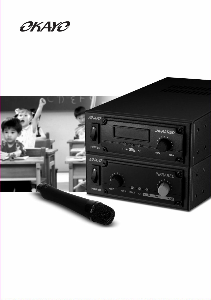
INFRARED HANDHELD MICROPHONE ILLUSTRATION
Please avoid your hand holding the top emitter and the bottom emitter
1.
Select a channel by A/B Channel Switch (9)
*
A CH -> Channel A (2.3 MHz)
*
B CH -> Channel B (2.8 MHz)
2.
Select output power by HI/LOW Selector (12)
*
HI -> Distance can reach to 20 M; power consumption around 300 mA
*
LOW -> Distance can reach to 15 M; power consumption around 200 mA
3.
Has been installed properly, press the power switch button (5) for 1 second, and
then the power indicator (4) Indicate has been turned on.
*
Lights green: power sufficient
*
Lights red: power insufficient; please replace or recharge rechargeable
batteries.
4.
Switch the button (8) to the Talk status when you intend to amplifier your speech;
switch the button (8) to the Mute status when you are temperately not using the
microphone.
Insufficient power influences the signal transmission. We
strongly recommend you using the capacity 2500 mAh
rechargeable batteries and dual-slot charger, HDC-502,
to maximize your performance.
6.
HDC-502
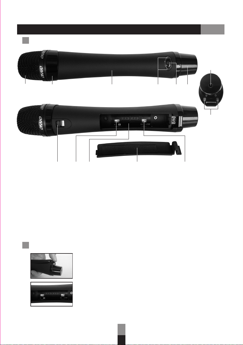
Operation Indication of EJ-501TI
Correctly hold EJ-501TI
5.
Press the power switch button (5) for 4 to 5 seconds
to turn the device off.
CAUTION !
Only Ni-MH rechargeable batteries are allowed to be charged. It may cause
leakage or explosion when charging un-rechargeable batteries.
Please take out batteries if the unit isn’t in use a period of time to avoid battery
leakage.