Okayo UHF-PLL EJ-701DR-PLUS User manual

UHF-PLL
Wireless Microphone System
EJ-702DR-PLUS Dual-channel Receiver
Single-channel Diversity Receiver
EJ-701DR-PLUS
User Manual

Illustration ........................................ ~ 2
Setup Procedure ......................................................................................... 3
Wireless Receiver Module DR-501A .............................................................. 4
Wireless Receiver Module DR-500 .......................................................... 5 ~ 6
Wireless Bodypack transmitter EJ-7T+/EJ-7XT+ ........................................ 7 ~ 8
Wireless Handheld microphone EJ-701TS+/EJ-701TM+ ............................ 9 ~ 10
Important Notes / Troubleshooting ............................................................... 11
Specifications ...................................................................................... 12 ~ 13
............................................. ....... 1
Thank you for the purchase of Wireless Microphone System EJ-701DR-PLUS and
EJ-702DR-PLUS. This manual will give comprehensive instructions and operation.
Please read it over before your use to perform this unit well.
Preface
Contents
This device complies with part 15 of the FCC Rules
Operation is subject to the following two conditions This device may not cause harmful interference and this device
must accept any interference received, including interference that may cause undesired operation.
.
: (1) , (2)
Notice:
The changes or modifications not expressly approved by the party responsible for compliance could void the user s authority
to operate the equipment.
’
FCC INFORMATION
The Federal Communication Commission Radio Frequency Interference Statement includes the following paragraph:
-- Reorient or relocate the receiving antenna.
-- Increase the separation between the equipment and receiver.
-- Connect the equipment into an outlet on a circuit different from that to which the receiver is connected.
-- Consult the dealer or an experienced radio/TV technician for help.
The equipment has been tested and found to comply with the limits for a Class B Digital Device, pursuant to part 15 of the FCC Rules.
These limits are designed to provide reasonable protection against harmful interference in a residential installation.
This equipment generates, uses and can radiate radio frequency energy and, if not installed and used in accordance with the instruction,
may cause harmful interference to radio communication.
However, there is no grantee that interference will not occur in a particular installation. If this equipment dose cause harmful interference
to radio or television reception, which can be determined by turning the equipment off and on, the user is encouraged to try to correct
the interference by one or more of the following measures:

1. Power Switch
2. Wireless Receiver Module DR-501A
3. Antennas
4. Balanced AF XLR Output
5. Unbalanced AF Output (6.3 mm jack)
6. AF Impedance Selection (for 5)
7. DC Power Socket
2
1
4 5 6 7
3
DC INPUT
12 15V/0.6A
Single-channel Diversity Receiver
Illustration
EJ-701DR-PLUS
1

2
1
4 5 6 7
3
DC INPUT
12 15V/0.6A
DC INPUT
12 15V/0.6A
EJ-702DR-PLUS Dual-channel Receiver
1. Power Switch
2. Wireless Receiver Module DR-500
3. Antennas
4. Balanced AF XLR Output
5. Unbalanced AF Output (6.3 mm jack)
6. AF Impedance Selection (for 5)
7. DC Power Socket
Power Supply
Please use our product
AC Switching Adaptor as
attached.
‘s
Illustration
2

AF OUT
LOW/HI
DC INPUT
12 15V/0.6A
AF OUT
LOW/HI
DC INPUT
12 15V/0.6A
Setup Procedure
Signal Connections
1. Connect 6.3 mm mic jack from Unbalanced AF Output to amplifier s MIC IN
and set “impedance” at “LOW”. Or connect 6.3 mm mic jack from “unbalanced
AF Output” to amplifier’s “LINE IN” and set “impedance” at “HI”. (The same
way can be applied in EJ-701DR-PLUS / EJ-702DR-PLUS.)
“ ” ’ “ ”
Amplifier
2. If using XLR mic jack connect it from
”Balanced AF Output” to amplifier’s “AUX IN”.
,
In order to prevent from the impedance from being too high thus producing
unexpected noise, please set “impedance” at "LOW” if you are connecting
a mic jack to a “low input” in the subordinate device.
3
If your subordinate device is with general input socket (e.g., LINE IN, AUX IN
, etc), please set ”impedance” at “HI” to avoid too low volume output - .
AF Impedance Selection (HI / LOW Control)
Remark: AF Impedance Selection only controls
Unbalanced AF Output (6.3 mm jack).

Turn “ eceiver power on/off control” knob (7) clockwise until a click occurs.
A text of “ ” will appear on LCD window for about 2 seconds and it
follows a channel number. The turning-on is successful. To turn it off, just turn
the control counterclockwise until a click occurs. A text of “ ” will appear
on LCD window and will disappear after 2 to 3 seconds.
R
Press and hold “Up or Down” button (6) for 1 second until channel number is
blinking. Select a desired number through “Up or Down” button (6). A selected
channel number will be confirmed in 1 second if no more adjustment made to it.
Change channel manually
How SYNC works
“ ” function can find a clean channel and assign it to transmitter in the
range, about 3 M. Just turn on your microphone or transmitter first and press
SYNC button, in few seconds the progress will be done. During synchronization,
the RF indicator will blink.
Please complete channel setup in one receiver first and then a second one
when you have more than 1 receiver.
Be sure to give different channel number to each receiver.
Wireless Receiver Module DR-501A
1. LCD Window
2. Antenna A and B indicator
3. RF signal indicator
4. AF signal indicator
5. Synchronization button
6. Channel up / down adjustment
7. Receiver power on / off control
and volume adjustment
Operation and Setting
4
15 6 74
3
2

15
4
3
2
Wireless Receiver Module DR-500
1. LCD
(Display Channel Number /
Reception Strength)
2. Channel A
Power Switch and Volume Control
3. Up / Down Frequency Selector
4. Frequency Set Key
5. Channel B
Power Switch and Volume Control
Window
Operation and Setting
Switch on/Switch off
1. Turn “Channel A / B” knob (2) / (5) clockwise until a click occurs then LCD window
will be on and a text of “On” will appear on LCD window. After 1 2 seconds,
the LCD window will show a channel number and signal strength, it means the
receiver module switched-on successfully.
,
~
2. Vice versa, turn “Channel A / B” knob (2) / (5) counterclockwise until a click occurs
then LCD window will show a text of “OFF” for about 2 ~ 3 seconds. LCD window will
be off after this procedure, switched-off successfully.
,
Setting and Selection of Channels
Press and hold key (4) to enter the mode of selecting the channels“SET”
1. While both Channel A and Channel B are available, the channel number of Channel
A shown on LCD window starts to blink. Press “Up” or “Down” Frequency Selector
keys (3) to look for your preferred channel number. Press “SET” key (4) again to
confirm the channel setting.
2. While only Channel A or Channel B is available, switch the channel number of
Channel A or Channel B directly.
3. If you don’t press any key for more than 10 seconds, it will leave the channel-
switching mode with channel number kept.
4. Channel A and Channel B cannot be set with the same channel number.
5
Searching for Available Channels
1. Press “Up” and “Down” Frequency Selector keys (3) simultaneously for more than
1 second, and then LCD window will show a text of without blinking.
Channel A and Channel B will be switched to available channels automatically.
If there is no any channel available, the channel numbers will still remain the same.

7
Press Up and Down Frequency Selector keys simultaneously on DR-500
module 1 for more than 1 second, you could find two available channels.
“ ” “ ” (3)
4. Using two wireless receiver modules simultaneouslyDR-500 :
Switch on two Transmitters used for Wireless Receiver Module 1 and adjust
the channel number accordingly.
Press Up Frequency Selector key on Wireless Receiver Module 2 for more
than 1 second, you could find available channel for Channel A.
“ ” (3)
Switch on the third Transmitter used for Wireless Receiver Module 2 and adjust
the channel number accordingly.
Press Down Frequency Selector key (3) on Wireless Receiver Module 2 for more
than 1 second, you could find available channel for Channel B.
“ ”
Switch on the forth Transmitter. Finalize the process of four channels used
simultaneously.
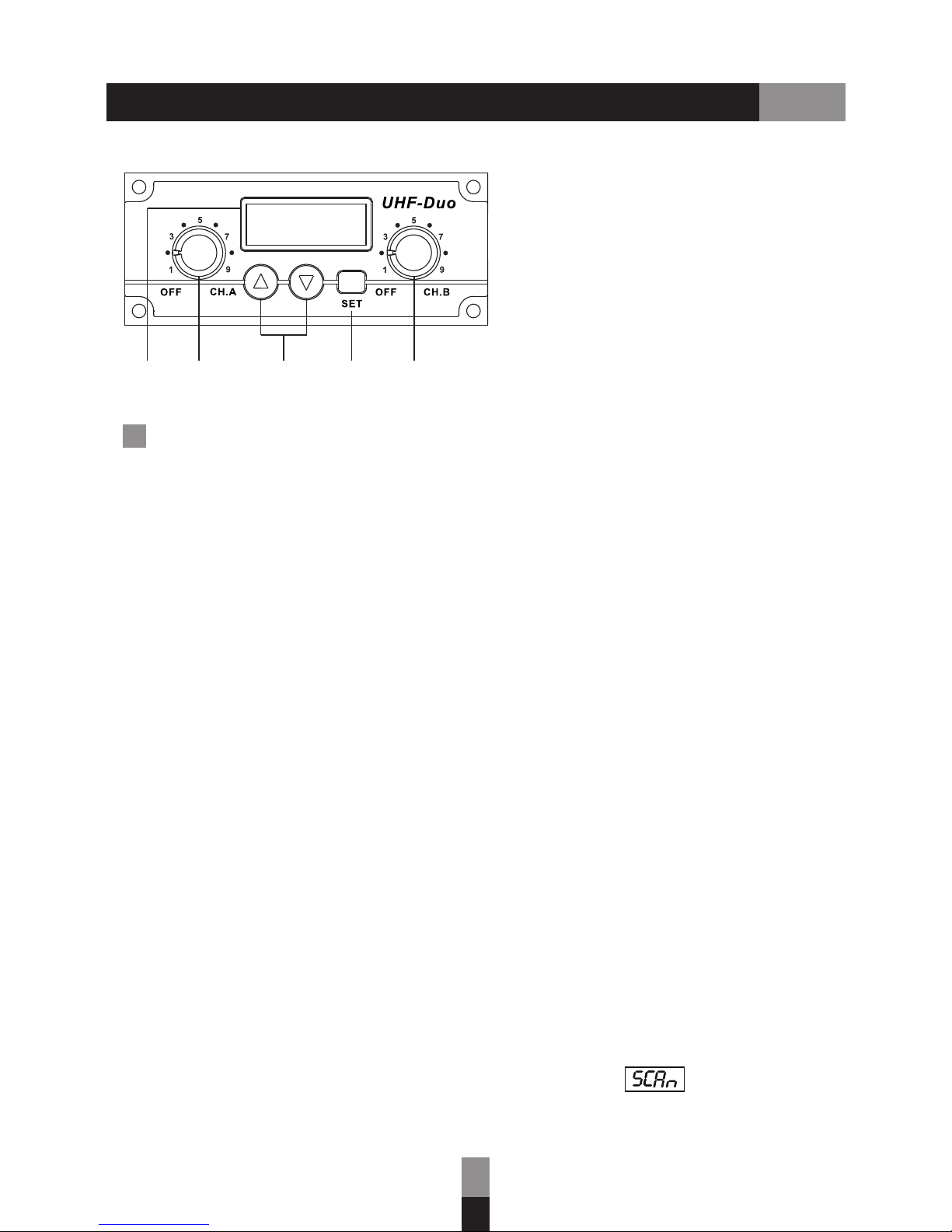
Setting of Group Number and SQ Value
1. Press “Set” key (4) and then switch on Channel A or Channel B to enter Group
and then LCD window would show (number will keep blinking).
setting,
2. Press “Up” or “Down” Frequency Selector keys (3) to look for your preferred
group number.
3. Press ”SET” key (4) to confirm the group setting or wait for 5 seconds to confirm
it automatically and then enter setting mode of SQ value.
4. Under setting mode of SQ value, LCD window will show (number will keep
blinking).
5. Press “Up” or “Down” Frequency Selector keys (3) to choose SQ value the value
will not be set in circulation.
,
6. Press “SET” key (4) again to confirm the group setting or wait for 5 seconds to
confirm it automatically and then back to normal switching-on mode.
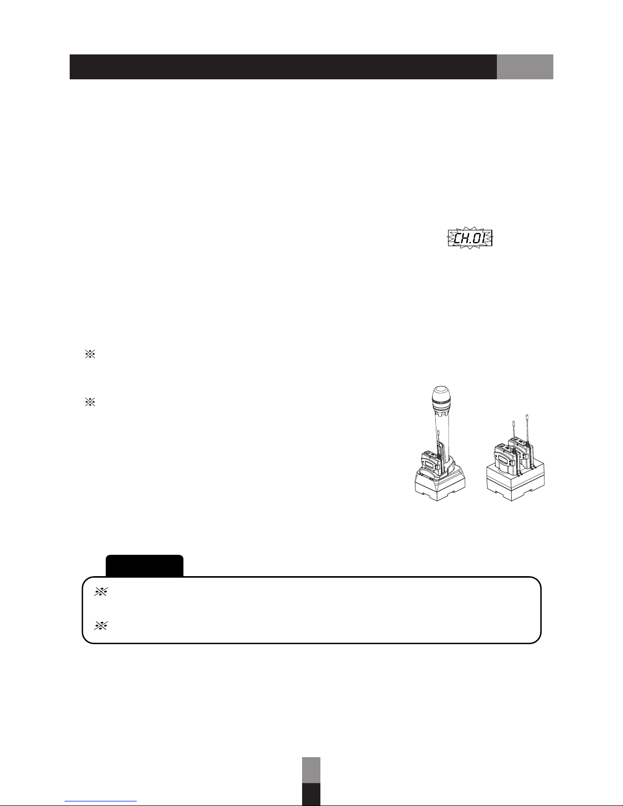
Please keep the distance between the Transmitter and the Receiver more than M2 .
Please keep the distance between the Transmitter and the Transmitter more than
0.5 M.
2. Press Up Frequency Selector key for more than second and then LCD window
will show , Channel A would be switched to available channel automatically.
If there is no channel available, the channel value would be kept the same.
“ ” (3) 1 ,
3. Press Down Frequency Selector key for more than second and then LCD
window will show , Channel B would be switched to available channel
automatically. If there is no channel available, the channel value would be kept
the same.
“ ” (3) 1 ,
A
B
CAUTION!
Wireless Receiver Module DR-500
6

1
2
3
4
5
6
7
8
9
10
11
1. Antenna
2. Mute Control
3. Power Switch
4. 3.5 mm push-in (EJ-7T+) or
Mini-XLR (EJ-7XT+) Microphone Input
5. LED Power Indicator
6. Sensitivity Selection
7. AUX In (3.5 mm)
8. Frequency Set
9. LCD Window
10. Turn Up / Down Frequencies Keys
11. Recharge Jack
Operation and Setting
Turn-on
Turn-off
Setting of Channel
Display of Channel
Turn on the “Power Switch” (3), the LCD window will show “On” and the Backlight
& “LED Power Indicator” (5) will be light on. After 1 second, the LCD window will
show channel number and battery life indicator.
Turn off the Power Switch the LCD will show OFF with backlight
on, and then turn off.
“ ” (3), window “ ”
After turning on the unit, the current channel is shown on the LCD
Press “Frequency Set” key (8) for 2 seconds to until the channel number stats to
blink, and then press “Up” or “Down” key (10) to select the channel from 1-96.
Press “Frequency Set” key (8) again to confirm the setting of channel or it will return
back to the original channel number after 10 seconds without pressing “Frequency
Set” key (8).
window.
※The transmitter and the receiver should be set on the same channel.
Press Up or Down key or press Up and Down keys simultaneously to
show current frequency value on the LCD window. The LCD window will go back to
normal after releasing fingers from keys.
“ ” “ ” (10) “ ” “ ” (10)
Wireless Bodypack Transmitter EJ-7T+/EJ-7XT+
7

HDC-707
HDC-702
CAUTION!!
Take out batteries when the devices won’t be operated in a long time.
leakage or even explosion!
DO NOT attempt to charge Alkaline battery. It will lead to battery
The performance of signal transmission is highly
involved with battery energy. Batteries with 1600
mAh (or above) in capacity are recommended.
The optional charger HDC-702 / 707 is an economy
solution for your daily use.
Frequency Pairing
1. After turning on the unit, the frequency pairing will be run once within 10 minutes.
The LED Power Indicator will be light on in blue for three times and the backlight
of LCD window will be on as well while frequency pairing successfully. While
changing to a new channel, the LED Power Indicator will be light on in blue
constantly.
2. Press Frequency Set key for less than seconds to enable frequency pairing
function again. During the process of frequency pairing, the LED Power Indicator
will be light on in blue blinkingly together with channel number blinkingly
shown on LCD window. If frequency pairing successfully, new channel number will
be shown on LCD window unblinkingly and the LED Power Indicator will be light on
in blue constantly. If frequency pairing unsuccessfully after turning-on for 20
seconds, it will back to the original channel number with LED Power Indicator light
on in blue constantly and the original channel number remained without blinking.
“ ” (8) 2
8
Notice: This function is available while only working with DR-501A.
Wireless Bodypack Transmitter EJ-7T+/EJ-7XT+

23 4 5 6 7
1
8911
LOW
HI
MUTE
10
1. Mesh head
2. Handheld tube
3. Setup button
4. LCD window
(channel, frequency, battery energy)
5. Up / Down button
6. Power indicator
7.
8. HI / Low / Mute
sensitivity selector
9. Battery door
10. Charging port
11. Button cap
Power ON / OFF button
1. Take off button cap (11) and pull off battery door (9).
2. Insert batteries correctly. (two AA 1.2 V Ni-MH rechargeable
batteries or 1.5 V Alkaline batteries) Put the button cap (11)
back.
CAUTION !
Wireless Handheld Mic EJ-701TS+/EJ-701TM+
Put Batteries in Microphone
3. This action ensures the battery door is locked and to prevent
from falling off. Insert 2 pcs of 1.5 V AA alkaline batteries or
1.2 V AA rechargeable batteries into the battery case, and then
close the battery door (9) tightly.
DO NOT use larger capacity battery.
(e.g. the Ni-MH battery with over 2300 mAh might
be stuck in battery room and can't be taken out!)
9
The differences between are mesh head and cartridge onlyEJ-701TS+ and EJ-701TM+ .

Operation and Setting
Turn-on / Turn-off
Setting of Channel
1. Press Power Switch key for second to turn on the unit. The LCD window will
show “On” first and then show channel number and battery life indicator after 1 2
seconds. The LED Power Indicator will be light on in blue as well.
“ ” (7) 1
~
2. Under any situation, the unit can be turned off if pressing Power Switch key
for more than 2 seconds.
“ ” (7)
After turning on the unit, the current channel is shown on the LCD window.
Press “Frequency Set” key (5) for more than 2 seconds until the channel number
starts to blink, and then press “Up” or “Down” key (5) to select the channel
from 1-96. Press “Frequency Set” key (3) again to confirm the setting of channel
number or it will return back to the original channel number after 10 seconds without
pressing any key.
HDC-702
The performance of signal transmission is highly involved with
battery energy. Batteries with 1600 mAh (or above) in capacity
are recommended. The optional charger HDC-702 is an economy
solution for you daily use.
CAUTION!!
Take out batteries when the devices won’t be operated in a long time.
leakage or even explosion!
DO NOT attempt to charge Alkaline battery. It will lead to battery
Frequency Pairing
1. After turning on the unit, the frequency pairing will be run automatically once.
2. The LED Power Indicator will be light on blinkingly in blue for three times and
then constantly while frequency pairing successfully.
3. Press Frequency Set key for less than seconds to enable frequency pairing
function again. If frequency pairing unsuccessfully after turning-on for 20 seconds,
it will back to the original channel number with LED Power Indicator light on in blue
constantly and the original channel number remained without blinking.
“ ” 2
4. The distance for frequency pairing should be less than meters. 3
10
Notice: This function is available while only working with DR-501A.
Wireless Handheld Mic EJ-701TS+/EJ-701TM+

Keep the device away from any heat source and in a
Do not leave it under sunlight or close to heater.
location with good ventilation.
DON’T operate the device in the rain or in humid circumstance to prevent failure.
Prevent the device from dropping.
Apply factory recommended power supply to this system only. It is dangerous and
risky when employing a unqualified power.
Troubleshooting
Failed to Power On
Be sure batteries are allocated and put in correct direction.
Be sure power adapter is plugged well.
No Sound Output
Be sure Mute button is not on.
Check if there is huge air interference nearby.
Be sure volume control on transmitter and receiver are turned properly.
Be sure transmitter and receiver stay at same channel.
Remove battery from transmitter when you won't use it for a long
while.
Charging contacts
Clean charging contacts regularly to ensure good connection with charger.
When any corrosion occurs, contact your dealer to change it if you can't repair it.
Important Notes
Avoiding heat and humidity
Replacing batteries
Make sure the substitute batteries are with same specifications.
Using incorrect batteries might lead to explosion or malfunction.
Acoustic feedback is overlarge
Adjust the volume of microphone and receiver module properly.
Failing to charge
Make sure the charger is connected with power supply correctly.
Make sure battery contacts are clean and free of corrosion.
Change batteries if the device still can t be charged.’
11

Specifications
Wireless coverage
Frequency response
Pre-emphasis
Dynamic range
Amb ient tempe rature
XLR 1V / 600 : Ω
Low : 80 mV / 2k Ω
Hi : 730 mV / 2k Ω
1.2 kg
210 x 215 x 44 mm
Φ6.3 mm MIC-out (mixer), XLR-balanced
-10° C ° C ~ +60
110 dB
50
70 Hz 1 kHz~7
DR-501A
Carrier frequency 514 865 MHz (country dependant)~
Channels 16 96 (frequency dependant)~
LCD window Channel, requency F
Channel adjustment select through UP and DOWN
DR-5 00
EJ-701DR-PLUS EJ-70 DR-PLUS2
Channel, Reception Strength
Frequency Set, UP and DOWN
Frequency modulation 24 MHz (max.)
T.H.D. < 0.5 %
70 M 100 ~60 9 M 0 ~
Dimensions (DxWxH)
Weight
Wireless Receiver
Silent mode Tone key and noise lock dual-squelch
Power supply AC switching power adapter 100 ~ 240 V, 12 15 V / 0.6 A ~
Audio output
Receiver
Receiver Module
Output level
12

10 mW
Less than 250 nW
Φ3.5 mm Mic in, Aux in
Wireless Bodypack Transmitter EJ-7T+/EJ-7XT+
Wireless Handheld Mic EJ-701TS+ / EJ-701TM+
Microphone capsule
Microphone capsule
Antenna
RF output
Audio input
Specifications
Condenser
Dynamic capsule
Flexible antenna
Spurious emission
Mute switch, Hi / Mid / Low switch
170 g (battery included)
26 x 64 x 88 mm
Dimensions (DxWxH)
Weight
2 x 1.2 V (Ni-MH 1600 mAh) AA type rechargeable batteries
2 x 1.5 V AA Alkaline disposable batteries
AF controls
Power requirements
Power supply 8 hours typical in Ni-M rechargeable batteriesH
14 hours typical in Alkaline disposable
10 mW
Less than 250 nW
Antenna
RF output
Built-in antenna
Spurious emission
Hi / Low / Mute switch
237 g (battery included)
26 (dia.) x 264 mm
Dimensions (ΦxL)
Weight
2 x 1.2 V (Ni-MH 1600 mAh) AA type rechargeable batteries
2 x 1.5 V AA Alkaline disposable batteries
AF controls
Power requirements
Power supply 8 hours typical in Ni-HM rechargeable batteries
14 hours typical in Alkaline disposable
13
Transmitter
Mini-XLR Microphone Input3.5 mm push-in
Input jack
EJ-7T+
EJ-7XT+
Microphone
EJ-701TS+
EJ-701TM+
Condenser capsule

10/14
This manual suits for next models
1
Table of contents
Other Okayo Microphone System manuals