OKO Tech DAC40 USB 9
8. Using with 37-channel micromachined membrane deformable mirror
«DAC-40-USB» can be used to drive a 37-channed micromachined
membrane deformable mirror (MMDM) produced by OKO Technologies. Two
amplifier boards and four cables from OKO Technology are required for this
purpose. Assembling of the system is described below.
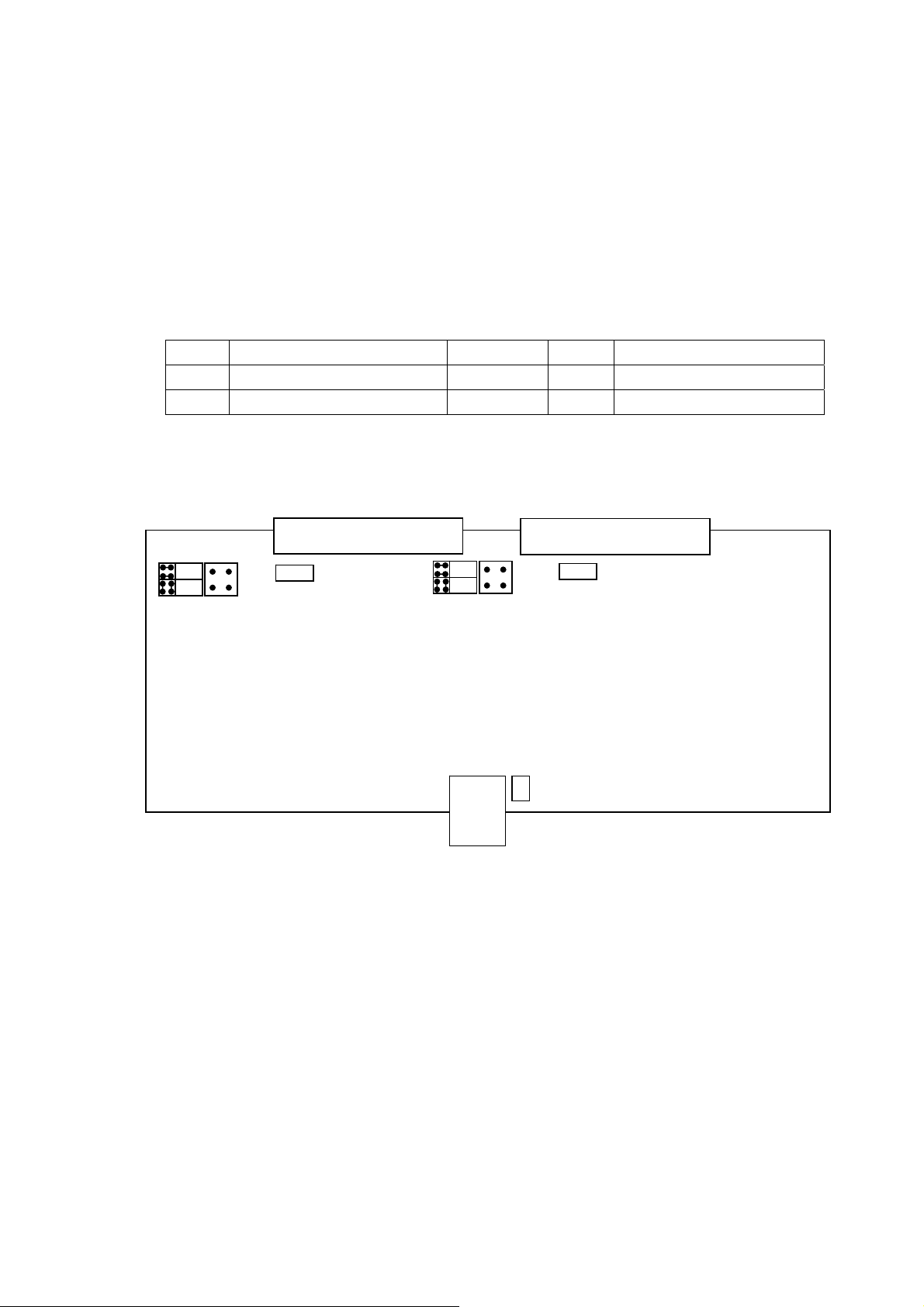
•Disconnect «DAC-40-USB» unit from your computer. In order to provide
ground to the mirror and connect it to the ground of the amplifier boards,
jumpers X3 and X4 of the unit should be set to the position 2-3. If the mirror
is supplied with a full set of control electronics, the jumpers should be
already properly configured.
•Connect the amplifier boards (or amplifier units) to «DAC-40-USB» unit
using 20 pins-to-26 pins cables, observing the order of numbering, e.g., the
amplifier board number 1 should be connected to X5 output connector,
whereas the board number 2 should be connected to X6 connector.
•Supply power to the amplifier boards (units) as specified in the mirror
manual.
•Connect «DAC-40-USB» to the computer using a USB cable. Turn on the
low voltage power supply, then the high voltage one.
•The folder /mmdm37ch_vc of the software CD contains simple command-
line utilities for control of the mirror, which are compiled with Visual C++
6.0. Enter this folder from the command line and type “am_set 4095”; it will
set the maximum voltage level at the output of the unit.
•Measuring the voltage between the ground pin (pin 20) and any control pin at
the output of any amplifier board, adjust it by turning the variable resistor R
until the maximum supply voltage for this mirror is achieved. If the mirror is
supplied with a full set of control electronics, the resistor Ris already
adjusted.
•Turn off the high voltage power supply. Connect the mirror to the amplifier
boards using 20 pins-to-20 pins cables, also observing the numbering. Fix the
cables to the optical table.
•Turn on the high voltage power supply. Now you can use the mirror.
The following utilities are provided to drive the mirror.
•“rotate” sets the maximum value (4095) to all channels of the mirror, one by
one.
•“am_set N” sets the same voltage Nto all actuators, where Nis in the range
0…4095.
•“19_set” sets 4095 to 20-37 channels of OKO 37ch mirror and 0 to other
channels.
•“set_channel N” sets 4095 to N-th channel and 0 to other channels.
•“smiley37” generate a smiley-like shape on the mirror.