OKTANTA PE4332 User manual

+7(812) 385-54-28 info@oktanta-ndt.ru
PEC Flaw Detector PE4332
Operation Manual
Saint Petersburg
2021

PEC Flaw Detector PE4332 Operation Manual
+7(812) 385-54-28
info@oktanta-ndt.ru 2
Contents
PURPOSE ........................................................................................................................................... 3
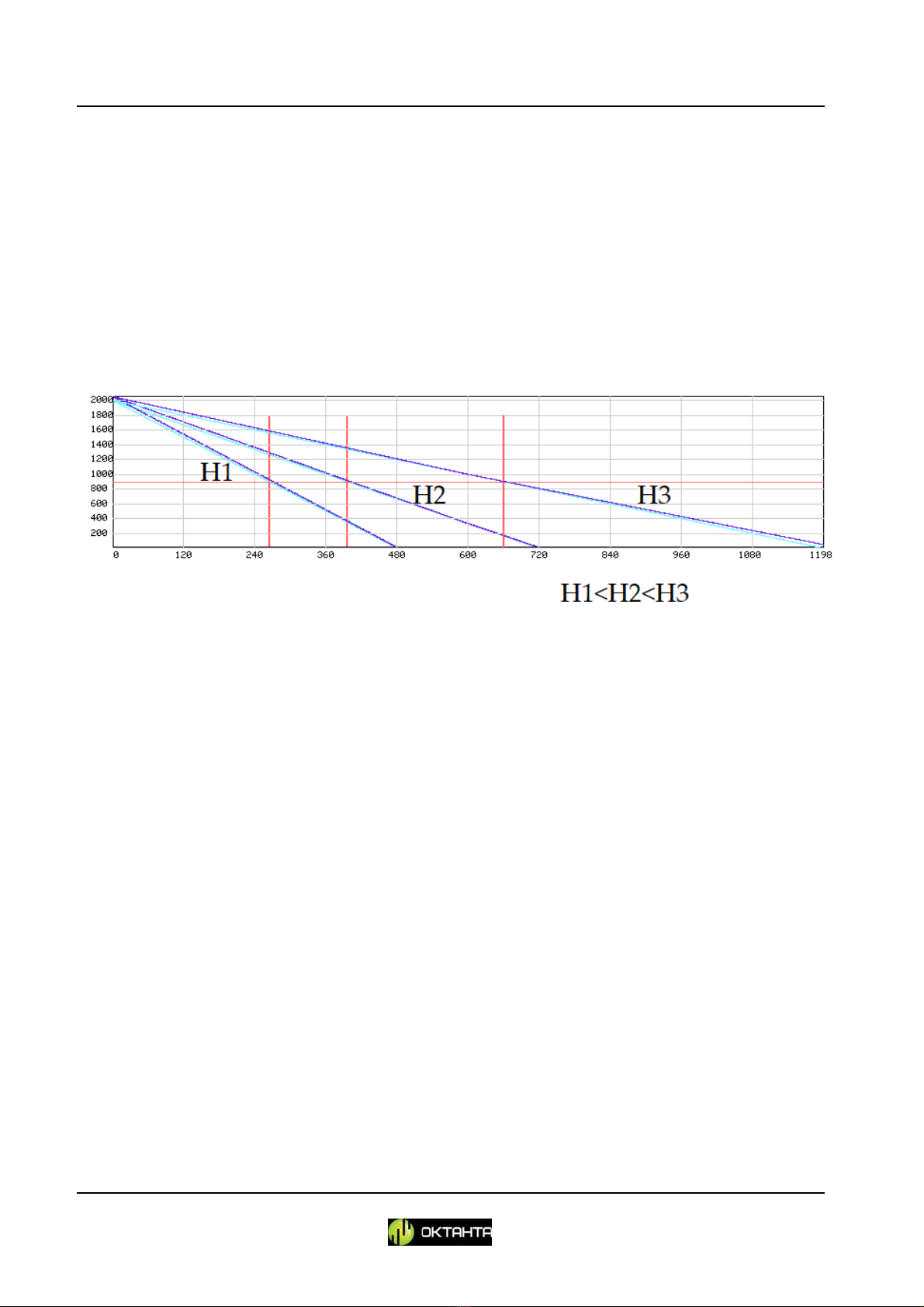
PRINCIPLE OF OPERATION.................................................................................................................. 5
TECHNICAL CHARACTERISTICS ............................................................................................................ 6
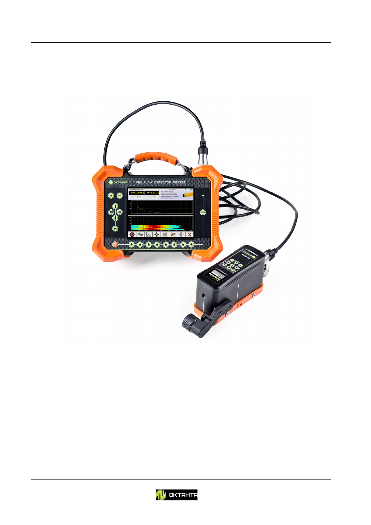
PEC FLAW DETECTOR APPEARANCE .................................................................................................. 7
Device ............................................................................................................................................ 7
Sensor ...........................................................................................................................................10
DEVICE MENU ...................................................................................................................................12
Scanning start/stop/continuation menu. .................................................................................13
Calibration ..............................................................................................................................15
Grid ........................................................................................................................................16
Test item parameters ..............................................................................................................24
Diagrams ................................................................................................................................31
Insulation thickness ................................................................................................................34
Thresholds ..............................................................................................................................35
Averaging................................................................................................................................37
Main menu .............................................................................................................................38
DEVICE OPERATION ..........................................................................................................................44
Sensor Selection............................................................................................................................44
Thickness Measurement ...............................................................................................................48
Scan mode ....................................................................................................................................50
Data Transfer ................................................................................................................................58
MAINTENANCE .................................................................................................................................58
Battery Replacement ....................................................................................................................58
Sensor Replacement .....................................................................................................................59
Encoder Installation and Removal .................................................................................................60
TRANSPORTATION AND STORAGE .....................................................................................................61
SCOPE OF SUPPLY .............................................................................................................................61
MANUFACTURER WARRANTY ...........................................................................................................62
INFORMATION ABOUT REPAIR ..........................................................................................................63

PEC Flaw Detector PE4332 Operation Manual
+7(812) 385-54-28
info@oktanta-ndt.ru 3
PURPOSE
The Pulsed Eddy Current Flaw Detector PE4332 (PEC Flaw Detector PE4332) is
designed to detect corrosion under insulation without removal of the latter. The
Device is used to inspect such items as:
Insulated pipelines including pipelines in operation:
Figure 1. Pipelines.
Insulated tanks:
Figure 2. Tanks.
Oil platform supports:
Figure 3. Oil platforms.

PEC Flaw Detector PE4332 Operation Manual
+7(812) 385-54-28
info@oktanta-ndt.ru 4
LNG tank supports:
Figure 4. LNG tanks.
Ship hulls with thick paint or epoxy coating:
Figure 5. Ship hull.
The Device allows testing such items without preliminary surface preparation
or insulation removal. The insulation can be represented with any non-conducting
coating, such as polyurethane, mineral wool, plastics, paint, or air. An insulation
casing can be made of aluminum or galvanized steel.

PEC Flaw Detector PE4332 Operation Manual
+7(812) 385-54-28
info@oktanta-ndt.ru 5
PRINCIPLE OF OPERATION
The Device operation is based on the pulsed eddy current technique of
nondestructive inspection. A Device sensor generates a pulsed magnet field, which
magnetizes a test item area located beneath it. Time of magnetization and
demagnetization of this area depends on the metal thickness.
The main tool that displays the demagnetization process is A-scan shown in
Figure 6:
Figure 6. A-scan appearance.
The greater is the metal thickness under the sensor, the longer is the
demagnetization process on A-scan and vice versa, the smaller is the metal thickness
under the sensor, the faster the demagnetization occurs. The Device analyses
parameters of the demagnetization process and, based on this analysis, measures the
mean metal thickness under the sensor.
The Device is subject to mandatory calibration at the test item; for correct
operation of the Device, it is necessary to know the nominal thickness of the test
item.

PEC Flaw Detector PE4332 Operation Manual
+7(812) 385-54-28
info@oktanta-ndt.ru 6
TECHNICAL CHARACTERISTICS
Measured thickness range for steel (depends on insulation
thickness and sensor, see Sensor Selection)
0 to 60 mm
Average thickness measurement error 10%
Thickness range for insulation coating (depends on insulation
thickness and sensor, see Sensor Selection)
0 to 300 mm
Minimum diameter of tested pipes 50 mm
Temperature of test item metal -100To
to +600С
Temperature of casing surface in place of sensor contact -20 to+60С
Working ambient temperature range -20 to +50C
Time of continuous operation without battery recharging 8 hours
Cable length 1.5 m, 5.5 m
Overall dimensions 246 x 315 x 32
mm
Weight 5 kg

PEC Flaw Detector PE4332 Operation Manual
+7(812) 385-54-28
info@oktanta-ndt.ru 7
PEC FLAW DETECTOR APPEARANCE
Figure 7 shows the appearance of the PEC Flaw Detector PE4332. You can see
the Device itself and the sensor connected with the Device using the cable.
Figure 7. PEC Flaw Detector PE4332 appearance.
Device
The Device is incorporated into a plastic impact-resistant housing with
protective rubber inserts. The Device display is protected with a hardened impact-
resistant glass. Figure 8 shows the detailed appearance of the Device.

PEC Flaw Detector PE4332 Operation Manual
+7(812) 385-54-28
info@oktanta-ndt.ru 8
Figure 8. Device appearance.
Numbers in the Figure stand for:
1 – Device carrying handle, 2 – Device display, 3 –Device keyboard, 4 –
connector for transducers, 5 – USB-A and USB-B connectors, 6 – recharger connector,
7 – holder for Device installation on flat surfaces
For Device display appearance, see Figure 9.
Figure 9. Device display.
There are five main screen panels. They are numbered and indicated in Figure
9:
Panel 1 This panel contains information on the connected sensor name,
GPS coordinates, current date and time, battery charge level, as well as
different indicators can be found at this panel. The indicators are as
follows:

PEC Flaw Detector PE4332 Operation Manual
+7(812) 385-54-28
info@oktanta-ndt.ru 9
Indicator of a switched-on light ,
Indicator of a switched-on encoder ,
Indicator of activated scan mode .
Panel 2 This panel provides information on the test item as well as
displays measured thickness of metal and current thickness of the item
insulation.
Panel 3 This panel displays A-scan of the Device.
Panel 4 This panel displays C-scan of the Device.
Panel 5 This panel displays icons with functional keys.
The Device has the keyboard. The functional keys of the keyboard are
described in Table 1.
Table 1. Keys of Device keyboard
Key
Key assignment
Name
Function
ON/OFF key
Switching on and off the
Device.
Back key
Return to the previous menu
items as well as closing the
menu
Left, Up, Down, Right
navigation keys
Navigation through the Device
menu
OK key
Setting of the selected
parameter in the menu of
electronic module
Menu key Access to and exit from the
main menu of the Device

PEC Flaw Detector PE4332 Operation Manual
+7(812) 385-54-28
info@oktanta-ndt.ru 10
MIN key
Display and locking A-scan on
the screen for a point with
minimum metal thickness
detected
Multi-functional keys
Various fu
nctions specified by
the icons
Sensor
Figure 10 shows the appearance of the sensor.
The sensor is made of impact-resistant plastics. Its display is protected with
hardened glass.
Figure 10. Sensor appearance.
Numbers in the Figure stand for:

PEC Flaw Detector PE4332 Operation Manual
+7(812) 385-54-28
info@oktanta-ndt.ru 11
1 – encoder, 2 – sensor display, 3 – sensor keyboard, 4 – cable connector.
Figure 11 shows the appearance of the sensor display.
Figure 11. Sensor display.
The sensor display shows the following information:
Indicator of a switched-on light ,
Indicator of a switched-on encoder ,
Indicator of activated scan mode ,
Metal thickness,
Insulation thickness,
Coordinates of the current position on C-scan.
The Device sensor has its own keyboard. The keyboard keys are described in
Table 2.
Table 2. Sensor keyboard.
Key designation Key name Key function
Start or stop the
continuous measuring
mode
Switch on or off of the
continuous measuring mode
Start of the single
measurement
Measurement of the test item
thickness
Navigation keys: Left
Up, Down
Right
Navigation through C-scan

PEC Flaw Detector PE4332 Operation Manual
+7(812) 385-54-28
info@oktanta-ndt.ru 12
"Word wraparound"
key Wraparound on the C-scan
"Light" key
Switching on and off of
the
light
"Encoder" key
Swit
ching on and off of the
encoder
WARNING!
During operation of the PEC Flaw Detector PE4332, the sensor generates a large
pulsed magnet field. Be careful when using the sensor as the field can magnetize such
sharp tools as a knife, pricker, needle, etc. Do not keep the sensor close to any
magnetic-field-sensitive equipment!!!
DEVICE MENU
Figure 12 shows the main window of the Device.
Figure 12. Device main window

PEC Flaw Detector PE4332 Operation Manual
+7(812) 385-54-28
info@oktanta-ndt.ru 13
The icons shown in the main window of the Device are provided in
Table 3:
Table 3. Icons above the keys in the main window of the Device
Icon Purpose
Access to scanning start/stop/continuation
menu
Access to Device calibration menu
Access to C-scan grid edition menu
Access to test item parameter change menu
Access to A-scan and C-scan navigation menu
Access to insulation thickness setting menu
Access to rejection requirements (rejection
thresholds) setting menu
Switching on and off of accumulation
Scanning start/stop/continuation menu.
This menu allows starting or interrupting the scan mode. The scan mode
allows measuring the thickness in nodes of the pre-set grid. The scan mode is
necessary to fill C-scan if it is required.
Figure 13 shows this menu.

PEC Flaw Detector PE4332 Operation Manual
+7(812) 385-54-28
info@oktanta-ndt.ru 14
Figure 13. Scanning start/stop/continuation menu.
This menu has three menu items between which you can navigate using the
keys of the Device keyboard. To select the appropriate menu item, press on
the key. These menu items allow to start new scanning, stop scanning, as well as
to continue the stopped scanning.
New scan
Figure 14 shows "Start new scanning" window. In this window, you can set the
name of the location where test is carried out; set the name of the site where test is
carried out; set the test item name and the Operator name.
Figure 14. New scanning window
To start scanning, press on the key.

PEC Flaw Detector PE4332 Operation Manual
+7(812) 385-54-28
info@oktanta-ndt.ru 15
Scanning stop
To stop scanning, select "Stop scanning" menu item and press on the key on
the Device keyboard.
Scanning continuation
To continue scanning, select "Continue scanning" menu item and press on the
key of the Device keyboard. This function can be used not only to continue the
stopped scanning, however, to continue the previous scans that were not completed.
For example, the user may have scanned only part of the test item and then he/she can
return to the test item few days later and continue scanning. To do this, the user shall
open the archive with non-completed scan (see Section "Main menu" / "Open file"),
open menu of scanning start/stop/continuation and select "Continue scanning". Do not
forget that in this case calibration shall be performed prior to scanning continuation.
WARNING! You can get access to "Scanning" menu through the Device main menu
key.
Calibration
Figure 15 shows the Device calibration window. To perform calibration, install
the sensor on the test item section with thickness known, set this thickness in the
Device and press on the key on the Device.

PEC Flaw Detector PE4332 Operation Manual
+7(812) 385-54-28
info@oktanta-ndt.ru 16
Figure 15. Device calibration window
The numbers are entered as follows:
select any digit place using functional keys; the icon of the
highlighted digit position will change to ,
change value from 0 to 9 for each digit position selected using the
keys,
If necessary, you can set the digit position value by pressing on the
keys.
Grid
When you use the scan mode, you shall put a measuring grid to the test item.
We propose to use our special self-adhesive film with a grid. You can also draw the grid
on the test item by yourself using, for example, a ruler and a marker. Figure 16 shows
the window for grid parameters setting.

PEC Flaw Detector PE4332 Operation Manual
+7(812) 385-54-28
info@oktanta-ndt.ru 17
Figure 16. Window with grid parameters.
To navigate through the window, use the navigation keys.
This menu contains the following items:
Grid scale
There are two scale options: dimensional scale (mm/mm) and non-
dimensional scale (123/ABC). The first option is used when the grid has fixed linear
dimensions; the second one is used when linear dimensions are not important. To
change the scale, use the keys or the keys with the icons.
Horizontal spacing
This parameter is used to set the grid spacing along the horizontal axis. This
parameter can vary from 1 to 2000 mm.
To change the parameter, use the keys under the
icons.
For quick entry, you can use the key under the icon. In this case, the
window shown in Figure 17 will appear.

PEC Flaw Detector PE4332 Operation Manual
+7(812) 385-54-28
info@oktanta-ndt.ru 18
Figure 17. Quick entry window.
To change over the digit position, use the keys or the keys under
the icons. To enter the given number, use the keys or the keys
under the icons.
Vertical spacing
This parameter is used to set the grid spacing along the vertical axis. This
parameter can vary from 1 to 2000 mm. Navigation through this menu item is the
same as through the "Horizontal spacing" menu item.
Horizontal scanning site length
This parameter is used to set the horizontal size of the scanning site. This
parameter can vary from 1 to 50 m. Navigation through this menu item is the same as
through the "Horizontal spacing" menu item.
Vertical scanning site length
This parameter is used to set the horizontal size of the scan site. This
parameter can vary from 1 to 5 m. Navigation through this menu item is the same as
through the "Horizontal spacing" menu item.
Save grid
The user can save the selected grid in the Device memory for further use. The
grid saving window is shown in Figure 18.

PEC Flaw Detector PE4332 Operation Manual
+7(812) 385-54-28
info@oktanta-ndt.ru 19
Figure 18. Grid saving window.
By default, the grid name is automatically generated from the grid
parameters; however, you can change the grid name as you wish. To this end, the
Device has the keyboard mode (see Figure 12). To navigate through the keyboard,
use the keys. The selected character is entered when the key is
pressed on. To complete entry of the name and to exit from this window, press on
the key under the icon (see Figure 18).
Table 4 shows the icons used for text entry.
Table 4. Keyboard icons
Icon Purpose
Switching on or off of the upper case
123 or ABC Change-over between letter mode and number
mode

PEC Flaw Detector PE4332 Operation Manual
+7(812) 385-54-28
info@oktanta-ndt.ru 20
en or ru Change-over of the language: English or Russian
Space Space key
Enter Saving information and exit from the keyboard
mode
. Quick change-over between the keys similarly
marked on the keyboard
Bck Erasion of one character
Clr or Undo Complete clearing of the entry field or
cancellation of entry field clearing
Grid loading
You can load the pre-saved grid for the test item. Figure 19 shows the window
in which you can select the pre-saved grid.
Table of contents
Other OKTANTA Measuring Instrument manuals
Popular Measuring Instrument manuals by other brands

Ametek
Ametek Jofra MTC-650 A MKII user manual

Maxcom
Maxcom MXOPM26-50 Series Technical specification

Endress+Hauser
Endress+Hauser PROFI BUS Proline Promag 53 PROFIBUS DP operating manual

SEPTENTRIO
SEPTENTRIO PolaRx5TR quick start guide

Hilti
Hilti PMA 31 operating instructions

Omron
Omron Sti G9SX-SM032 Series user manual