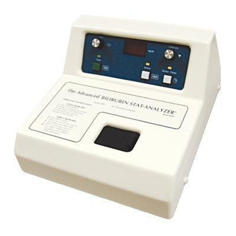
Advanced Bilirubin Stat-Analyzer BR2 User manual

The Advanced® Bilirubin
Stat-Analyzer™ Photometer
Models BR2 and BR2E
for Neonatal Samples
User’s Guide
BR25EN Rev14 06338

Copyright
This user’s guide is copyrighted by Advanced Instruments, Inc. with all
rights reserved. Under copyright laws, this guide may not be reproduced in
any form, in whole or part, without the prior written consent of Advanced
Instruments.
© 2003 Advanced Instruments, Inc.
Advanced Instruments has reviewed this guide thoroughly. All material
contained within is believed reliable, but the accuracy and completeness
are not guaranteed or warranted, and are not intended to be representations
or warranties concerning the product described.
Hot-Line®Service
If you have any questions or problems regarding the proper operation of
your instrument, please contact our Hot-Line Service department by call-
ing one of the following numbers.
• 800-225-4034 (toll-free within the USA and Canada; after normal busi-
ness hours, dial extension 2191)
• +US 781-320-9000 (elsewhere)
• 781-320-0811 (fax)
ii
The Advanced®Models BR2 and BR2E User’s Guide

Table of Contents
Supplies, Parts & Accessories v
Safe Use vii
Symbol conventions vii
General cautions viii
Foreword xi
Intended Use xi
Operating Principles
A. General xi
B. Total Bilirubin xi
C. Direct Bilirubin xii
Figure 1: BR2 and BR2E Block Diagram xii
Chapter 1 — Installation & Setup 1
A. Unpack the instrument 1
B. Functions of controls 2
C. Operational requirements 4
D. Operational checks 8
Figure 2: Model BR2 and BR2E Photometer and Accessories 3
Figure 3: Major Parts and Controls 5
Figure 4: Back Panel 6
Table 1: Model BR2 and BR2E Photometer Packing List 3
Chapter 2 — Instrument Operation 9
Hazardous material cautions 9
A. Warm up 9
B. Test kits 10
iii

C. Sample preparation and handling 11
D. Procedure 12
E. Abbreviated operating instructions 14
Chapter 3 — Calibration & Standards 17
A. Standards 17
B. Bilirubin-equivalent solutions 18
C. Calibration procedure 19
Chapter 4 — Troubleshooting & Service 21
Service & maintenance cautions 21
A. Obtaining service 22
B. Troubleshooting checks 24
C. Preventive Maintenance 24
D. Fuse replacement 24
Appendices 27
Appendix A — Troubleshooting table 27
Appendix B — Product specications 29
Appendix C — Regulatory notices 31
Appendix D — Warranty and warranty duties 35
Appendix E — Symbol denitions 39
Appendix F — Product Disposal and Recycling 43
Appendix G — Service log 45
Index 47
iv
The Advanced®Models BR2 and BR2E User’s Guide

Supplies, Parts &
Accessories
v
To order parts and accessories, contact the Advanced
Instruments Customer Service Department.
• 800-225-4034 (toll-free within the USA and Canada)
• +US 781-320-9000 (elsewhere)
• 781-320-3669 (fax)
DESCRIPTION
Total Bilirubin Test Kit, Reagents and Cuvettes for 100
determinations
Total and Direct Test Kit, Reagents and Cuvettes for 100
determinations
Disposable Cuvettes
BR2/BR2E User’s Guide
BR2/BR2E Service Manual
Power Cord (specify voltage and country)
PART NO.
B2A101
B2A102
B2A800
BR25
BR25SM

vi
Notes:
The Advanced®Models BR2 and BR2E User’s Guide

Safe Use
To reduce the risk of bodily injury, electric shock, re, and
damage to your instrument, please read and observe the precau-
tions in this User’s Guide.
• If the product is used in a manner not in accordance with
the equipment design, operating instructions or manufactur-
er’s recommendations, the operation of the product may be
impaired to the extent that a safety hazard is created.
•Do not attempt to perform electrical work if you are not
fully qualied. This manual is not a substitute for electrical
training.
Symbol conventions
The exclamation point within an equilateral triangle is
intended to alert the user to the presence of important oper-
ating and maintenance (servicing) instructions in the litera-
ture accompanying this product.
The lightning ash with arrowhead symbol within an equi-
lateral triangle is intended to alert the user to the presence of
uninsulated dangerous voltage within the product’s enclo-
sure that may be of sufcient magnitude to constitute risk of
electric shock to persons.
The static symbol within an equilateral triangle is intended
to alert the user to the presence of internal components that
could be damaged by static electricity.
This static symbol is intended to alert the user to the pres-
ence of a specic component that could be damaged by stat-
ic electricity.
vii

viii
The Advanced®Models BR2 and BR2E User’s Guide
This symbol indicates the presence of alternating current (AC).
This symbol indicates the presence of a fuse.
This symbol indicates the presence of protective earth ground.
General cautions
• This product should be operated only with the type of power source
indicated on the product’s electrical ratings label. Refer to the
installation instructions included with the product.
• If the power cord provided is replaced for any reason or if an alter-
nate cord is used, the cord must be approved for use in the local
country. The power cord must be approved for the product’s listed
operating voltage and be rated at least 20% greater than the ampere
ratings marked on the product’s electrical ratings label. The cord
end that connects to the product must have an IEC 60320 connector.
• Plug the product into an approved grounded electrical outlet.
• Do not disable the power cord’s grounding plug.
• If an extension cord or power strip is used, make sure that the cord
or strip is rated for the product, and that the total ampere ratings of
all products plugged into the extension cord or strip do not exceed
80% of the cord’s or strip’s rating limit.
• Route power cords so that they will not be walked on, tripped on, or
pinched by items placed upon or against them. Pay particular atten-
tion to the plug, electrical outlet, and the point where the cord exits
the product.
• Do not pull on cords and cables. When unplugging cords or cables,
grasp the corresponding connector.

ix
Safe Use
• Do not install or use this product in any area subject to extreme
short-term temperature variations, or locations that exceed the speci-
ed operating environment temperatures.
• Never use this product in a wet area.
• To avoid injury or re hazard, do not operate this product in an
explosive atmosphere.
• Do not install or use the product on an unstable, non-level work sur-
face.
• Do not operate this product with the covers removed or unsecured.

x
The Advanced®Models BR2 and BR2E User’s Guide
Notes:

Foreword
Operating Principles
xi
A. General
The Advanced Models BR2 and BR2E Bilirubin Stat-
Analyzer Photometers are dual-arm, dual-wavelength, nar-
row-bandpass photometers that measure Bilirubin (TBR) and
Azobilirubin (DBR) absorbance quantitatively. The digital
readout is calibrated to read bilirubin in milligrams per deci-
liter (mg/dL) for the BR2 or micromoles per liter (µmol/L)
for the BR2E of serum or plasma (see Appendix B). Figure
1 identies the major components of the instruments.
The BR2 wavelengths are xed and will not shift during the
life of the instrument.
B. Total Bilirubin
The maximum light absorption of bilirubin occurs at a wave-
length of 454 nm. Oxyhemoglobin (HbO2) has nearly equal
Intended Use
The Advanced Models BR2 and BR2E Bilirubin Stat-Analyzers,
when used by a trained operator, provide a rapid, accurate deter-
mination of Total and Direct Bilirubin in neonates.

absorbance at 454 and 540 nm. In the BR2, the absorbance at 540
nm (HbO2) is subtracted from the absorbance at 454 nm (TBR +
HbO2). The remainder corresponds to TBR concentration corrected
for oxyhemoglobin up to 600 mg/dL.
Light from an incandescent source is collimated and directed
through a cuvette containing the diluted sample. The transmitted
light is split by a ber optic beam splitter into 454-nm and 540-nm
channels, each made monochromatic by a narrow-bandpass interfer-
ence lter.
Matched solid-state photo-detectors and signal processing electron-
ics measure the transmittances at 454 and 540 nm and display the
TBR concentration digitally.
C. Direct Bilirubin
Direct Bilirubin is measured as the change in absorbance at 540 nm
due to the formation of azobilirubin, using a two-minute, timed-end-
point modication to the Malloy and Evelyn method.
After TBR has been measured on a sample, that same sample is
acidied with HCl, establishing an absorbance baseline. Next,
diazotized sulfanilic acid is added. Under these conditions, the con-
xii
Figure 1: BR2 and BR2E Block Diagram
Cuvette
Lens
Lamp
Fiber optic
Beamsplitter
Filters Photo
Detectors Switch
Signal
Processor
Digital
Readout
mg/dL
or
µmol/L
Total
Direct
The Advanced®Models BR2 and BR2E User’s Guide

jugated (Direct) bilirubin fraction will react to form azobilirubin
which has maximum light absorption at 540 nm. At the end of the
two-minute reaction period, the digital display locks in to hold the
DBR readout until the next test is initiated.
xiii
Foreword

xiv
The Advanced®Models BR2 and BR2E User’s Guide
Notes:

1Installation & Setup
In order to set up your instrument properly, it is important that
you read and follow the steps in this section. Please follow these
steps carefully and be sure to read Chapter 2 — Instrument
Operation before attempting to run tests on your instrument.
A. Unpack the instrument
To unpack the instrument, take the following steps.
1. Carefully unpack the instrument, accessories and sup-
plies, and inspect them for shipping damage. Use the
enclosed packing list to verify that all items have been
received.
2. Save the instrument’s shipping boxes and packag-
ing material in case future transport of the instrument
becomes necessary.
3. If any item on the packing list appears to be missing
from your shipment, please search carefully through
and under all packing materials. If the item is not
found, notify your receiving department immediately.
Advanced Instruments can only be responsible for items
reported missing within 10 days of a shipment’s arrival.
4. If you receive any damaged items, save the cartons and
packing material those items came in for inspection by
1

the insurer. The carrier, dealer and Advanced Instruments must
be notied within 24 hours in order for your warranty and insur-
ance to apply. Have the transportation company inspect items,
ll out a “Report of Concealed Damage,” and le your claim.
Then, notify Advanced Instruments immediately for repair or
replacement.
5. Fill out the warranty card enclosed. Mark the appropriate boxes
if you wish to receive additional information. Mail or FAX to
781-320-8181.
B. Functions of controls
1. Power switch (gure 3, item 1); marked (“I”) and (“O”) located
on the back of the instrument. The power switch should nor-
mally be left on ( I) continuously to allow the BR2 to provide
maximum stability.
2. Back Panel
a. Fuse and line-cord socket (gure 4). Includes a power-pro-
grammer card to allow operation from either 100-120 VAC
or 200-240 VAC, as required (see section C).
b. DBR-Timer screwdriver adjustment. Factory set at 2 min-
utes ±10 seconds.
3. Front Panel
a. Total button (gure 3, item 2). When pressed, selects the
proper mode for calibration and TBR determination and
lights the Total lamp above the button.
b. Direct button (gure 3, item 6). When pressed, selects the
proper mode for DBR determination, switches the Total
lamp off, and the Direct lamp on above the buttons.
2
The Advanced®Models BR2 and BR2E User’s Guide

3
Installation & Setup
Figure 2: Model BR2 and BR2E Photometer and Accessories
Quantity Part No. Description
1 BR2 Bilirubin Stat-Analyzer Photometer
1 Power Cord (as specied by customer)
1 99073 1/16” Hex Wrench
1 B2A102 Total and Direct Bilirubin Test Kit
1 90P01 Advanced®User Information CD-ROM
1 BR25 User’s Guide
1 BR25-6 Warranty Card
1 3D3P021 Customer Satisfaction Card
Table 1: Model BR2 and BR2E Photometer Packing List

c. Direct Timer button (gure 3, item 8). Should be pressed
after entering the Direct mode as in “b” above and adding
diazo reagent as instructed in Chapter 2, Section D. Starts
the DBR reaction timer and lights the Direct Timer lamp
above the button.
After 2 minutes and ±10 seconds, the DBR reaction timer
locks the readout and ashes the Direct Timer lamp until
either the Total or Direct button is pressed.
d. Zero control (gure 3, item 3). Used to establish a zero
baseline in both the Total and Direct modes.
e. Calibrate control (gure 3, item 7). Used in the Total
mode, to calibrate the readout with a bilirubin standard of
known value.
C. Operational requirements
1. Location. The BR2 should be placed in a well-ventilated, tem-
perature-controlled environment, away from direct drafts from
heating, air conditioning, or other equipment.
2. Grounded Outlet Required. A three-prong grounded
(earthed) 100-240 VAC, 50-60Hz outlet capable of supplying
1/4 ampere at 100 VAC or 1/8 ampere at 240 VAC is required
within ve feet of the instrument.
WARNING This instrument must be properly grounded
(earthed). The grounding pin of the power plug is
connected to the cabinet to provide a noise shield
around sensitive components.
If the instrument is not grounded properly, its
operation will be impaired and a safety hazard
may exist. It is not enough to simply plug the
4
The Advanced®Models BR2 and BR2E User’s Guide

instrument into a grounding outlet. Have
the outlet tested.
3. Power. The BR2 must be properly set for the voltage
available on-site; it can be connected for operation
from either 100-120 VAC or 200-240 VAC. The prop-
er power selection is made by means of the voltage
selector card behind the fuse block in the back of the
instrument (Figure 4).
Check the voltage indicator pin in the fuse block in the
back of the instrument next to the power cord. If the
AC voltage of the power outlet intended for the instru-
ment is within the 100-120 VAC range, the pin should
indicate 120V; if the power outlet AC voltage is within
the 200-240 VAC range, the pin should indicate 240V.
If the voltage selection requires correction, it may be
accomplished as follows:
5
Installation & Setup
Figure 3: Major Parts and Controls
Power Switch (1),
Fuse Holder and
Power Socket (Behind)
(4)
Direct Timer
Button (8)
Direct
Button (6)
Cuvette
Chamber Cover (9)
Calibrate Control (7)
Readout (5)
Zero
Control (3)
Total Button (2)

a. The rocker-type power switch is on the rear of the BR2 next
to the power cord; rmly press the rocker end labeled “O”
to turn the instrument off.
b. Unplug the power cord from the back of the instrument.
c. Use a small screwdriver to pry the fuse holder out of the
back of the instrument.
d. The voltage selector printed circuit card is located in the
small compartment next to the fuse holder.
NOTE The voltage indicator assembly is loosely attached to
the voltage selector card; leave it attached. Do not
remove the indicator assembly from the selector card.
With the aid of the small screwdriver, pull the voltage selector
card out of its mounting slot in the compartment.
6
Figure 4: Back Panel
Indicator Pin
Voltage Selector Card
Fuse Block
Voltage Selector Card Orientation
The Advanced®Models BR2 and BR2E User’s Guide
Other manuals for Bilirubin Stat-Analyzer BR2
1
This manual suits for next models
1
Table of contents
Other Advanced Measuring Instrument manuals
Popular Measuring Instrument manuals by other brands

Siargo
Siargo MF4003 user manual

Sper scientific
Sper scientific 850068 instruction manual

Rice Lake
Rice Lake Healthweigh Adjusting instructions

Smart Tweezers
Smart Tweezers ST5SBT user manual
Maico
Maico LW 9 Mounting and operating instructions

MULTI MEASURING INSTRUMENTS CO.,LTD.
MULTI MEASURING INSTRUMENTS CO.,LTD. MCL-4000F instruction manual
