OKTANTA EM1401 User manual

ЕМ1401UT_M_921807721
+7(812) 385-54-28 info@oktanta-ndt.ru
EM1401 / EM1401 UT Thickness Gauge
Operation Manual
Saint Petersburg

EM1401 / EM1401 UT EMA Thickness Gauge. Operation Manual.
+7(812) 385-54-28
info@oktanta-ndt.ru 2
CONTENTS
CONTENTS ................................................................................................................................ 2
INTENDED USE..................................................................................................................... 4
PRINCIPLE OF OPERATION ........................................................................................... 4
TECHNICAL SPECIFICATIONS .................................................................................... 5
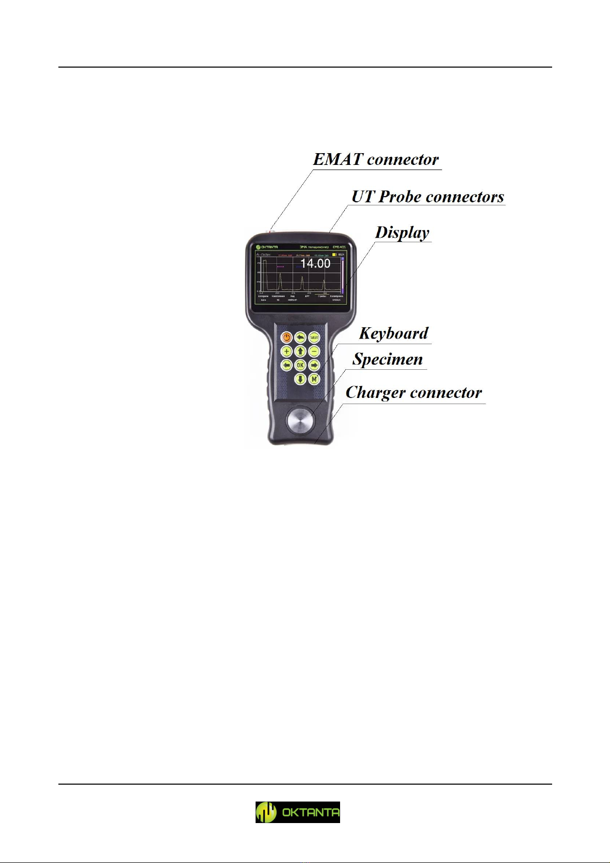
OPERATION DESCRIPTION ........................................................................................... 7
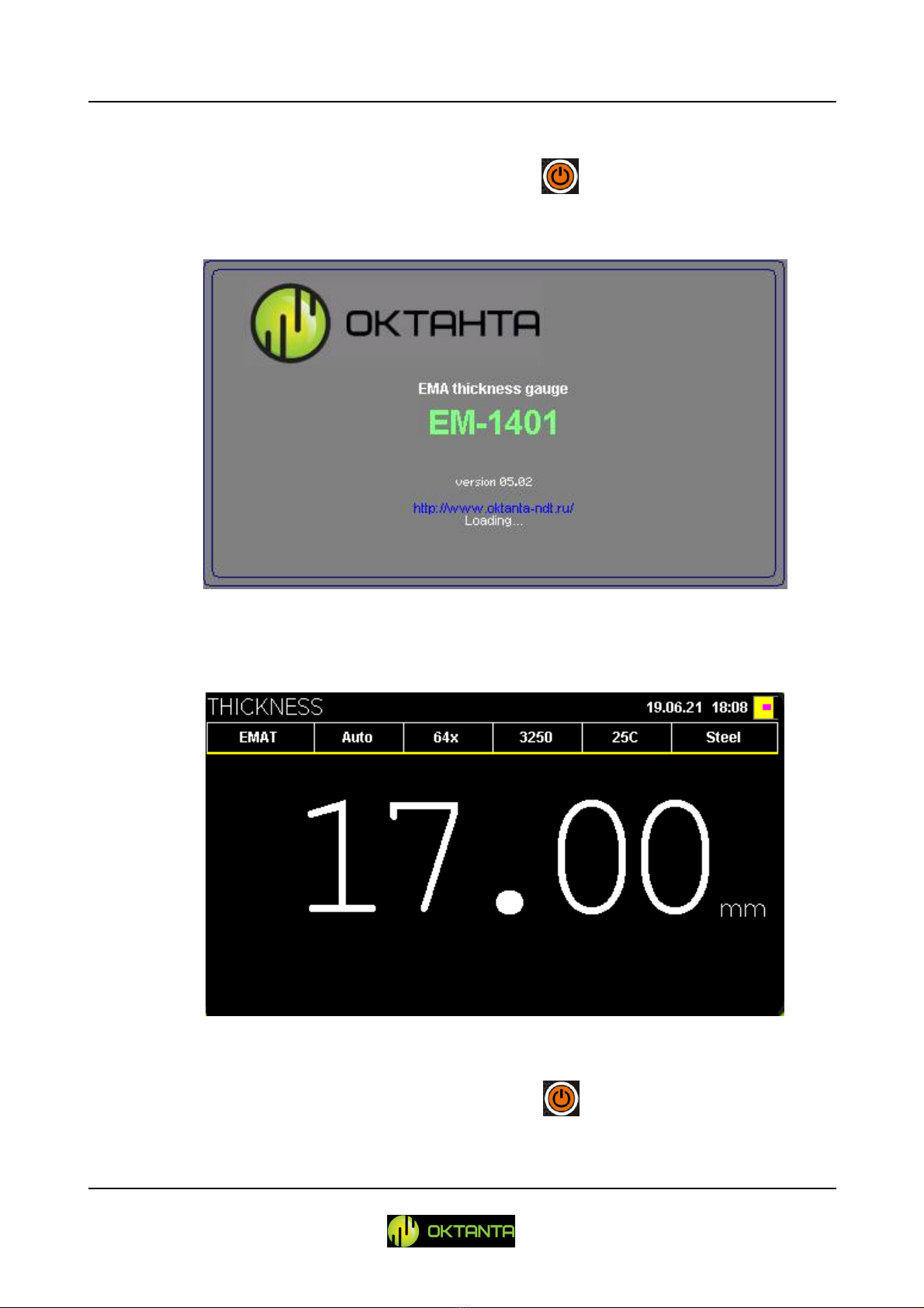
Device Switching On and Off ...................................................................................... 9
Information Display Mode Selection ...................................................................... 10
Thickness Window........................................................................................................ 11
A-scan window............................................................................................................... 18
B-scan window ............................................................................................................... 27
C-scan window ............................................................................................................... 33
User menu ........................................................................................................................ 39
Transducer Selection .................................................................................................... 41
Thickness Measurements using the Device .......................................................... 42
Data Transfer to PC ...................................................................................................... 43
Device Operation Features ......................................................................................... 44
Battery Charge ................................................................................................................ 44
DEVICE CALIBRATION TEST PROCEDURE ...................................................... 45
MAINTENANCE ................................................................................................................. 48
Transducer Replacement ............................................................................................. 48
Battery Replacement .................................................................................................... 48
TRANSPORTATION AND STORAGE ...................................................................... 49
SCOPE OF SUPPLY ........................................................................................................... 50
Basic configuration ....................................................................................................... 50
Optional equipment ...................................................................................................... 50
MANUFACTURER WARRANTY ............................................................................... 51

EM1401 / EM1401 UT EMA Thickness Gauge. Operation Manual.
+7(812) 385-54-28
info@oktanta-ndt.ru 3
WARRANTY CERTIFICATE ........................................................................................ 51
INFORMATION ABOUT REPAIR .............................................................................. 52
INFORMATION ABOUT CALIBRATION TEST .................................................. 53

EM1401 / EM1401 UT EMA Thickness Gauge. Operation Manual.
+7(812) 385-54-28
info@oktanta-ndt.ru 4
INTENDED USE
The EM1401 / EM1401 UT thickness gauge (further, the Device) is intended
to measure thickness of steel pipe walls, flat steel, rods, and other products made of
steel as well as aluminum and other metals using both non-contact electro-magnetic
transducers and traditional contact piezoelectric transducers (for EM1401 UT version).
PRINCIPLE OF OPERATION
The Device measures time during which the acoustic wave transits through the
test object. The measured time is converted into thickness using the specified value of
speed of ultrasonic wave propagation.
The Device can be connected both to EMA transducers and to contact PE
(piezoelectric) transducers.
A special data processing algorithm designed by Oktanta allows to measure the
test object thickness correctly even in the presence of disruptors such as metal
anisotropy, several reflectors and external noise. The Device enables to eliminate
influence of the human factor making the thickness measurements completely
automatic.

EM1401 / EM1401 UT EMA Thickness Gauge. Operation Manual.
+7(812) 385-54-28
info@oktanta-ndt.ru 5
TECHNICAL SPECIFICATIONS
For EMA transducer (EM1401, EM1401 UT)
Measured thickness range for steel 2 to 80 mm
Measured thickness range without gap for steel 2 to 120 mm
Thickness measurement error 0.08 mm
Permissible gap between the sensor and the test object
for ЕМТ14012 transducer
up to 4 mm
Permissible gap between the sensor and the test object
for ЕТМ14013 transducer
up to 6 mm
Permissible skew of the sensor relative to the test object
surface normal
± 25
Minimum permissible radius of curvature of the test
object surface
≥10 mm
Operating frequency 4 MHz
Working ambient temperature range -20 to +50
C
Operating temperature range of the test object surface -20 to +80
C
(-20 to +750C
using the EMT14014Т
transducer*)
Maximum number of measurements per second 16
For PE transducer (EM1401 UT)
Measured thickness range for steel for EDC5P10FS15
transducer
2 to 300 mm
Measured thickness range for steel for EDC5P7.2FS10
transducer
1 to 150 mm
Measured thickness range for steel for EDC10P5F3
transducer
0.5 to 20 mm

EM1401 / EM1401 UT EMA Thickness Gauge. Operation Manual.
+7(812) 385-54-28
info@oktanta-ndt.ru 6
Operating frequency 10 MHz for EDC10P5F3
5 MHz for EDC5P10FS15,
EDC5P7.2FS10
Thickness measurement error 0.08 mm
Maximum number of measurements per second 2
Operating temperature range of the test object surface -5 to +50
C
For both sensor types (EM1401, EM1401 UT)
Acoustic speed adjustment range 1000 to 9999 m/s
with 1 m/s
increments
Time of continuous operation without battery recharging
7 hours
Overall dimensions 122 x 231 x 42 mm
*The EMT14014T transducer is not intended for long-term use at 750 ºС. The maximum
temperature of long-term use of this transducer is 300 ºС. The objects with temperature of 300 ºС to
750 ºС shall be measured during short periods of time with 15 s intervals between measurements

EM1401 / EM1401 UT EMA Thickness Gauge. Operation Manual.
+7(812) 385-54-28
info@oktanta-ndt.ru 7
OPERATION DESCRIPTION
Device Appearance
Thickness gauge appearance
At the top of the Device, there are a connector for EMA transducers and two
connectors for PE transducers. The Device has a color liquid crystal display screen to
display measurement results. The Device is controlled by a keyboard with 11 push-
buttons. At the bottom of the Device, there is a connector for a recharger.

EM1401 / EM1401 UT EMA Thickness Gauge. Operation Manual.
+7(812) 385-54-28
info@oktanta-ndt.ru 8
Below are the functions of the control buttons.
The On/Off button switches on/off the Device;
The Back button allows the user to return to the previous menu items and
to close the menu;
The Up button allows the user to navigate in the Device menu, change
the A
-
scan scale and adjust the strobes and thresholds
;
The Down button allows the user to navigate in the Device menu, change
the A-scan scale and adjust the strobes and thresholds;
The Left button allows the user to navigate in the Device menu and adjust
the strobes;
The Right button allows the user to navigate in the Device menu and adjust
the strobes;
The "OK" button sets the parameter selected in the Device menu;
The Menu button opens/closes the Device menu;
The "Save" button saves data in the C-scan.
The Plus button allows the user to navigate in the Device menu;
The Minus button allows the user to navigate in the Device menu;

EM1401 / EM1401 UT EMA Thickness Gauge. Operation Manual.
+7(812) 385-54-28
info@oktanta-ndt.ru 9
Device Switching On and Off
To switch the Device on, press and hold the button during 3 s. A window
with information about the Device software version appears on the display.
Window with information about Device software version
Then a window with measured thickness appears.
Window with measured thickness
To switch the Device off, press and hold the button.

EM1401 / EM1401 UT EMA Thickness Gauge. Operation Manual.
+7(812) 385-54-28
info@oktanta-ndt.ru 10
Information Display Mode Selection
The Device allows to visualize A-scan, B-scan, and C-scan. To switch between
the information display modes, use the and buttons Press the button once
to switch to the A-scan display mode.
A-scan display mode
Press the button again to switch to the B-scan display mode.
B-scan display mode
Then, press the button again to switch to the C-scan display mode.

EM1401 / EM1401 UT EMA Thickness Gauge. Operation Manual.
+7(812) 385-54-28
info@oktanta-ndt.ru 11
C-scan display mode
Press the button again to switch to the thickness display mode.
Thickness Window
The figure below shows the Thickness window.
Thickness window
The top of the screen displays the following information:
Name of the selected transducer;

EM1401 / EM1401 UT EMA Thickness Gauge. Operation Manual.
+7(812) 385-54-28
info@oktanta-ndt.ru 12
Thickness measurement mode. Possible settings are as follows: auto, one
strobe and two strobes;
Averaging number used in the Device;
Selected acoustic speed;
Selected temperature of the test object;
Selected material of the test object;
When you press the button, the window will be as shown in the figure
below:
Change of parameters
Within this window, you can change the applicable transducer, measurement
mode, averaging number, temperature as well as select the material of the test object
and perform calibration. To select the appropriate menu item, press on the and
buttons. To change the selected menu item, press on the button.
Transducer Selection
The figure below shows the transducer selection window.

EM1401 / EM1401 UT EMA Thickness Gauge. Operation Manual.
+7(812) 385-54-28
info@oktanta-ndt.ru 13
Transducer Selection
The Device allows to select among four transducer types:
EMAT: electromagnetic acoustic transducer. This setting shall be selected
when any EMA transducer is used.
EDC10P5F3: piezoelectric transducer to measure thickness ranging from
0.5 to 20 mm. This transducer operates at 10 MHz.
EDC5P7.2FS10: piezoelectric transducer to measure thickness ranging
from 1 to 150 mm. This transducer operates at 5 MHz.
EDC5P10FS15: piezoelectric transducer to measure thickness ranging
from 2 to 300 mm. This transducer operates at 5 MHz.
Thickness Measurement Mode Selection
The Device enables to use one of three thickness measurement modes: auto,
manual with one strobe and manual with two strobes. For more details on manual
measurement modes, see "A-scan window".
Accumulation Number Selection
The figure below shows the accumulation number selection window.

EM1401 / EM1401 UT EMA Thickness Gauge. Operation Manual.
+7(812) 385-54-28
info@oktanta-ndt.ru 14
Accumulation Number Selection
By default, the Device uses 128 accumulations. Thus, the final thickness
measurement is performed using 128 measured values by averaging them. When the
test object has a poor surface quality or heavy corrosion, increase the number of
accumulations up to 256-512.
Calibration
The calibration window appearance is shown in Figure below:
Calibration
The Calibration menu has three items:
Sensor. This item is available when one of three piezoelectric transducers
is selected. The front cover of the Device includes the calibrations sample (see "Device
Appearance") The piezoelectric transducers shall be calibrated prior to operation start

EM1401 / EM1401 UT EMA Thickness Gauge. Operation Manual.
+7(812) 385-54-28
info@oktanta-ndt.ru 15
by calculating delay in prism which sizes constantly decrease as the transducer wears
out. When this item is selected, the Device window will be as follows:
Sensor calibration
When the Calibration text appears on the screen, put the sensor on the
calibration sample coated with contact liquid. Then, the Device will calculate the delay
in prism and will measure the thickness of this sample as 3 mm.
Thickness. This calibration enables to calculate the acoustic speed in
automatic mode according to the known thickness. To calibrate according to the known
thickness, place the sensor on the object with known thickness and select this
calibration item. Then, the following window will display:
Calibration according to known thickness

EM1401 / EM1401 UT EMA Thickness Gauge. Operation Manual.
+7(812) 385-54-28
info@oktanta-ndt.ru 16
In the opened window, press the , , , and buttons to specify
the known thickness value; then press the button.
Speed. This item enables to specify the acoustic speed.
The acoustic speed setting window is shown below:
Acoustic speed setting
In this window, press the , , , and buttons to specify the
known acoustic speed value; then press the button.
WARNING!
All EMA transducers intended for this Device use transverse ultrasonic wave. The
typical speed of the transverse wave for the steel is 3250 m/s.
All PE transducers intended for this Device use longitudinal ultrasonic wave. The
typical speed of the longitudinal wave for the steel is 5950 m/s.
Temperature
The acoustic speed depends on the material temperature. Therefore, different
acoustic speed shall be used for different temperatures. The Device can automatically
correct the acoustic speed depending on the test object temperature. To use this feature,

EM1401 / EM1401 UT EMA Thickness Gauge. Operation Manual.
+7(812) 385-54-28
info@oktanta-ndt.ru 17
set the test object temperature in this menu. The window used to enter the test object
temperature is shown in Figure below.
Test object temperature entry
In this window, press the , , , and buttons to specify the
test object temperature; then press the button.
WARNING!
To measure the thickness of the heated objects, use the special EMT14014T EMA
transducer. Use of the other transducers for the objects which temperature exceed
80C can cause their failure.
Metal
This item is used to select the material of the test object. The selected material
influences both the acoustic speed and the function of the acoustic speed dependence
on the temperature. Therefore, correct selection of the material is very important. The
material selection window is shown below:

EM1401 / EM1401 UT EMA Thickness Gauge. Operation Manual.
+7(812) 385-54-28
info@oktanta-ndt.ru 18
Test object material selection
To select the required material, use the , and buttons/
A-scan window
The A-scan window appearance is shown in Figure below:
A-scan appearance

EM1401 / EM1401 UT EMA Thickness Gauge. Operation Manual.
+7(812) 385-54-28
info@oktanta-ndt.ru 19
A-scan Scale Change
The user can change the scale of the A-scan display. To change the scale, press
the button or the button while being in the A-scan window.
In this case, SCALE appears on the screen
A-scan scale change mode
In this mode, you can change the A-scan scale using the and buttons
you can also change the display area using the and buttons.
Upon selection of the position and size of the scaled area, press the button
or the button.
Context Menu
To operate with the A-scan and strobes and to calibrate the Device, a special
context menu is used. To open the context menu, press the button. Then, a
menu consisting of six items will appear at the screen bottom. You can navigate
through the menu items using the and buttons

EM1401 / EM1401 UT EMA Thickness Gauge. Operation Manual.
+7(812) 385-54-28
info@oktanta-ndt.ru 20
Context ("OK") menu
To close the context menu, change one of the menu settings by pressing the
button, or press the button.
Thickness Measurement Algorithm Selection
The Device has three thickness measurement algorithms: an automatic
algorithm, a thickness measurement algorithm using one strobe and a thickness
measurement algorithm using two strobes.
The automatic algorithm is suitable for most applications and allows to obtain
the thickness without user intervention.
The thickness measurement algorithm using one strobe calculates the position
of the maximum in the red strobe and converts the obtained value into thickness. The
position of the red strobe and its length are specified by the user. It is recommended to
use the algorithm for the test objects made by casting, as well as for the test objects
prone to severe corrosion.
The thickness measurement algorithm using two strobes calculates the
positions of the maximums in the red and blue strobes. The Device calculates the
thickness using the difference between the positions of the maximums in the red and
blue strobes. The position of the strobes and their lengths are specified by the user.
To enter the menu of thickness measurement algorithm selection, press the
button. The algorithm is selected by the and buttons. After selection of the
required algorithm, press the button.
This manual suits for next models
1
Table of contents
Other OKTANTA Measuring Instrument manuals