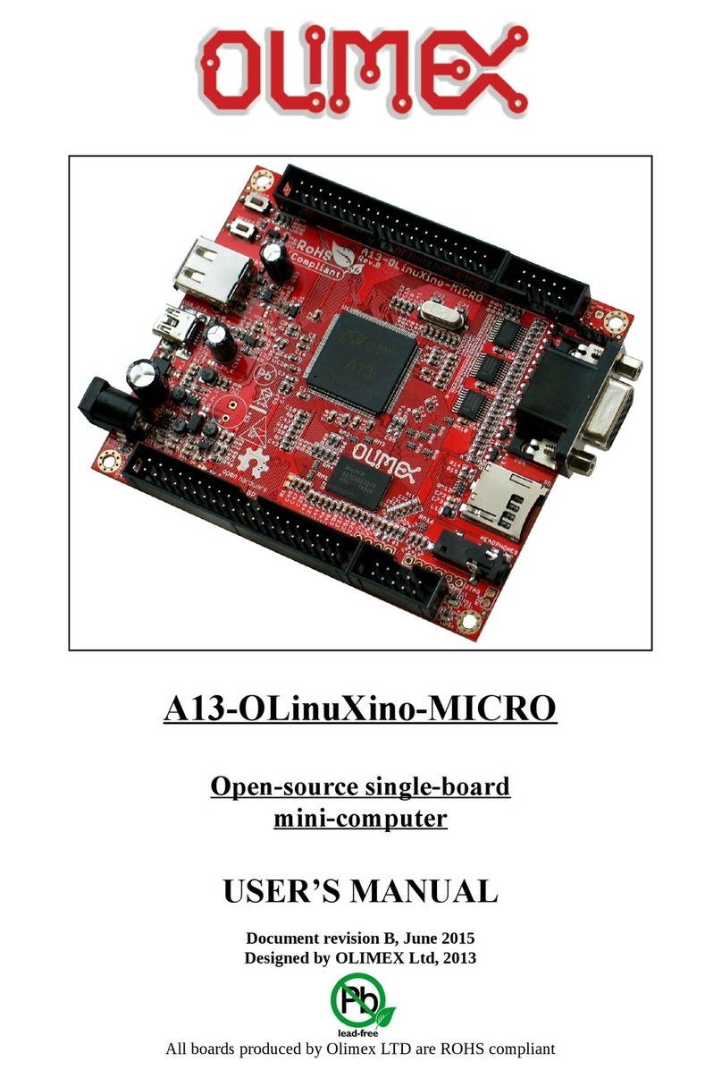
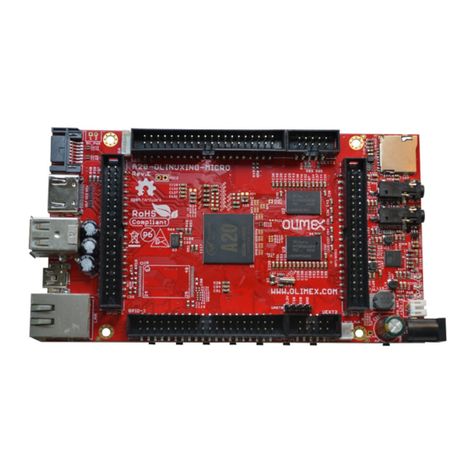
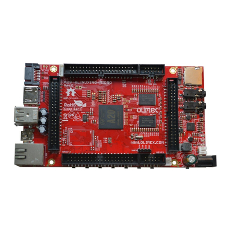
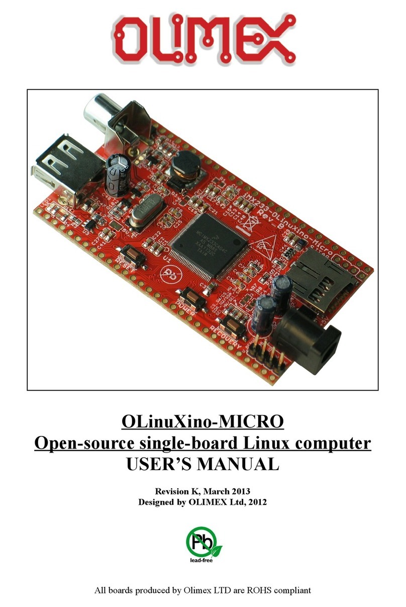
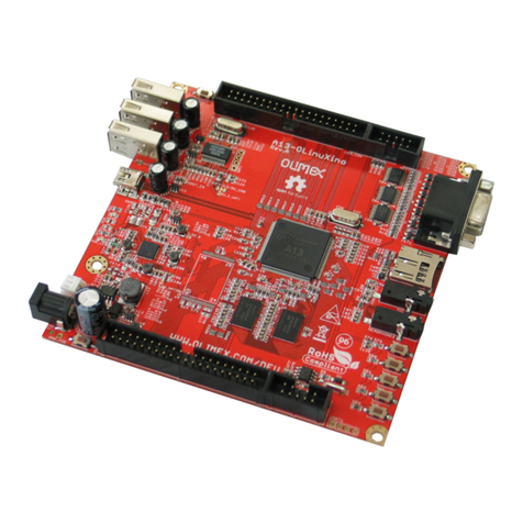
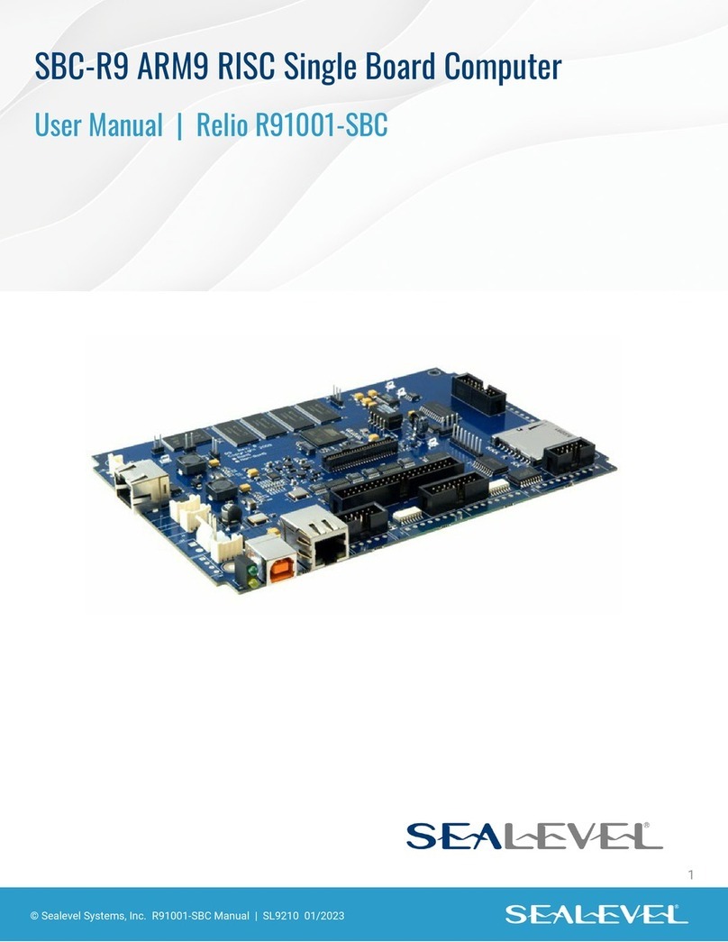
OLIMEX A13-OLinuXino User manual

A13-OLinuXino and A13-OLinuXino-WIFI
Open-source single-board
Android 4.0 mini-computer
U ER’ MANUAL
Revision F, March 2013
Designed by OLIMEX Ltd, 2012
All boards produced by Olimex LTD are ROHS compliant
Elcodis.com electronic components distributor
All manuals and user guides at all-guides.com

OLIMEX© 01 A13-OLinuXino user's manual
DI CLAIMER
© 01 Olimex Ltd. Olimex®, logo and combinations thereof, are registered trademarks of Olimex Ltd.
Other product names may be trademarks of others and the rights belong to their respective owners.
The information in this document is provided in connection with Olimex products. No license, express
or implied or otherwise, to any intellectual property right is granted by this document or in connection
with the sale of Olimex products.
The Hardware project is released under the Creative Commons Attribution-Share Alike 3.0 United States
License. You may reproduce it for both your own personal use, and for commercial use. You will have to
provide a link to the original creator of the project http://www.olimex.com on any documentation or website.
You may also modify the files, but you must then release them as well under the same terms. Credit can be
attributed through a link to the creator website: http://www.olimex.com
The software is released under GPL.
It is possible that the pictures in this manual differ from the latest revision of the board.
The product described in this document is subject to continuous development and improvements. All
particulars of the product and its use contained in this document are given by OLIMEX in good faith.
However all warranties implied or expressed including but not limited to implied warranties of
merchantability or fitness for purpose are excluded. This document is intended only to assist the reader in the
use of the product. OLIMEX Ltd. shall not be liable for any loss or damage arising from the use of any
information in this document or any error or omission in such information or any incorrect use of the
product.
This evaluation board/kit is intended for use for engineering development, demonstration, or evaluation
purposes only and is not considered by OLIMEX to be a finished end-product fit for general consumer use.
Persons handling the product must have electronics training and observe good engineering practice
standards. As such, the goods being provided are not intended to be complete in terms of required design-,
marketing-, and/or manufacturing-related protective considerations, including product safety and
environmental measures typically found in end products that incorporate such semiconductor components or
circuit boards.
Olimex currently deals with a variety of customers for products, and therefore our arrangement with the user
is not exclusive. Olimex assumes no liability for applications assistance, customer product design, software
performance, or infringement of patents or services described herein.
THERE I NO WARRANTY FOR THE DE IGN MATERIAL AND THE
COMPONENT U ED TO CREATE OLINUXINO. THEY ARE CON IDERED
UITABLE ONLY FOR OLINUXINO.
Page of 37
Elcodis.com electronic components distributor
All manuals and user guides at all-guides.com

OLIMEX© 01 A13-OLinuXino user's manual
Table of Contents
DI CLAIMER ............................................................................................................. 2
CHAPTER 1: OVERVIEW ........................................................................................ 5
1. Introduction to the chapter ....................................................................................................... 5
1.1 Features ..................................................................................................................................... 5
1.2 Target market and purpose of the board ............................................................................... 6
1.3 Board variants .......................................................................................................................... 6
1.4 Organization ............................................................................................................................. 6
CHAPTER 2: ETTING UP THE OLINUXINO BOARD ..................................... 7
2. Introduction to the chapter ....................................................................................................... 7
2.1 Electrostatic warning ............................................................................................................... 7
2.2 Requirements ........................................................................................................................... 7
2.3 Powering the board .................................................................................................................. 8
2.4 Prebuilt software ...................................................................................................................... 9
2.5 Button functions in Android ................................................................................................. 10
2.6 How we configured the Android image ................................................................................ 10
2.6.1. Getting the Android DK tools .................................................................................................................. 10
2.6.2. Adding information for the board in the Linux ........................................................................................ 10
2.6.3. Installing the DK tools .............................................................................................................................. 11
2.6.4. Connecting the A13-OLinuXino ............................................................................................................... 12
2.6.5. Downloading the default config file and script tool .................................................................................. 13
2.6.6. Applying the script and uploading the confing ......................................................................................... 13
2.6.7. Restarting the A13-OLinuXino .................................................................................................................. 13
2.7 Configuration of hardware in the Debian image ................................................................ 13
CHAPTER 3: A13-OLINUXINO BOARD DE CRIPTION ................................. 14
3. Introduction to the chapter ..................................................................................................... 14
3.1 Layout (top view) ................................................................................................................... 14
CHAPTER 4: THE ALLWINNER A13 MICROCONTROLLER ....................... 15
4. Introduction to the chapter ..................................................................................................... 15
4.1 The microcontroller ............................................................................................................... 15
4.2 Block diagram ........................................................................................................................ 17
CHAPTER 5: CONTROL CIRCUITY ................................................................... 18
5. Introduction to the chapter ..................................................................................................... 18
5.1 Reset ........................................................................................................................................ 18
5.2 Clocks ...................................................................................................................................... 18
5.3 Power supply circuit .............................................................................................................. 18
CHAPTER 6: CONNECTOR AND PINOUT ...................................................... 19
6. Introduction to the chapter ..................................................................................................... 19
6.1 Communication with the A13 ............................................................................................... 19
6.1.1 U B communication ..................................................................................................................................... 19
Page 3 of 37
Elcodis.com electronic components distributor
All manuals and user guides at all-guides.com

OLIMEX© 01 A13-OLinuXino user's manual
6.1.2 UART1 interface ........................................................................................................................................... 20
6.2 D/MMC slot .......................................................................................................................... 21
6.3 UEXT module ......................................................................................................................... 22
6.4 GPIO-1 (General Purpose Input/Output) 10pin connector .............................................. 23
6.5 GPIO-2 (General Purpose Input/Output) 40pin connector .............................................. 23
6.6 LCD_CON 40pin connector ................................................................................................. 25
6.7 PWR Jack ............................................................................................................................... 26
6.8 Headphones and microphone connector .............................................................................. 26
6.9 Battery connector ................................................................................................................... 27
6.7 VGA video connector ............................................................................................................. 27
6.8 Jumper description ................................................................................................................ 28
6.8.1 CE_NAND_E ................................................................................................................................................ 28
6.8.2 3.3V_OPTION, 1.5V_E ................................................................................................................................ 28
6.8.3 5V_E .............................................................................................................................................................. 28
6.8.4 HO T_EN, 5V_E_WIFI, WIFI-3.3V/5V_U B .......................................................................................... 28
6.9 Additional hardware components ........................................................................................ 28
CHAPTER 7: CHEMATIC .................................................................................. 30
7. Introduction to the chapter ..................................................................................................... 30
7.1 Eagle schematic ...................................................................................................................... 30
7.2 Physical dimensions ............................................................................................................... 32
CHAPTER 8: REVI ION HI TORY AND UPPORT ........................................ 33
8. Introduction to the chapter ..................................................................................................... 33
8.1 Document revision ................................................................................................................. 33
8.2 Board revision ........................................................................................................................ 35
8.3 Useful web links and purchase codes ................................................................................... 36
8.4 Product support ..................................................................................................................... 37
Page 4 of 37
Elcodis.com electronic components distributor
All manuals and user guides at all-guides.com

OLIMEX© 01 A13-OLinuXino user's manual
CHAPTER 1: OVERVIEW
1. Introduction to the chapter
Thank you for choosing the OLinuXino single board computer from Olimex! This document
provides a user’s guide for the Olimex OLinuXino board. As an overview, this chapter gives the
scope of this document and lists the board’s features. The document’s organization is then detailed.
The OLinuXino development board enables code development of applications running on the
microcontroller A13, manufactured by Allwinner Technology from China.
OLinuXino is an open-source, open-hardware project and all documentation is available to the
customer.
1.1 Features
•A13 Cortex A8 processor at 1GHz, 3D Mali400 GPU
•51 MB RAM
•6-16VDC input power supply, noise immune design
•3 + 1 USB Host, 3 available for users 1 for (optional) WIFI RTL8188CU 80 .11n 150Mbit
module on board
•1 USB OTG which can power the board
•SD-card connector for booting the Linux image
•(optional) 4GB NAND flash
•VGA video output – 800 x 600 resolution
•LCD signals available on connector so you still can use LCD if you diasble VGA/HDMI
•Audio Output
•Microphone input
•RTC PCF8536 on board for real time clock and alarms
•5 Keys on board for android navigation
•UEXT connector for connecting addtional UEXT modules like Zigbee, Bluetooth, Relays,
etc
•GPIO connector with 68/74 pins and these signals : 17 for adding NAND flash; for
connecting LCDs; 0+4 including 8 GPIOs which can be input, output, interrupt sources; 3x
I C; x UARTs; SDIO for connectinf SDcards and modules; 5 system pins: +5V, +3.3V,
GND, RESET, NMI
•(Optional low cost 7" LCD with touchscreen)
Page 5 of 37
Elcodis.com electronic components distributor
All manuals and user guides at all-guides.com

OLIMEX© 01 A13-OLinuXino user's manual
1.2 Target market and purpose of the board
The boards from the OLinuXino family are easy to setup and powerful. They are suitable for
embedded programming enthusiasts, Linux and Android gadget fans and also professionals (since
its low cost makes it very good solution for application orientated embedded systems). The main
usage of the board is software embedded development without the urge of understanding perfectly
the hardware.
The strong points of the boards are the processor speed, the mobility of the board and the low ratio
price to productivity.
Customers have full access to the technical documentation of the board. The software is released
under General Purpose License and the board is considered open-hardware.
1.3 Board variants
There are two major board variants. According to the names: A13-OLinuXino and A13-OLinuXino-
MICRO.
The base model has also two flavors: A13-OLinuXino and A13-OLinuXino-WIFI. The first one is
the base model that goes without any operating system image on board, while the second has two
additional components – a WIFI module on the board and NAND memory with stored Android
image.
The information on A13-OLinuXino-Micro will be added at a later time but so far the board is most
likely to differ from the base A13-OLinuXino by having only 1 USB host, 1 USB OTG, no power
connector, no NAND memory, no WIFI, no audio out connector, less buttons.
1.4 Organization
Each section in this document covers a separate topic, organized as follow:
–Chapter 1 is an overview of the board usage and features
–Chapter provides a guide for quickly setting up the board and software notes
–Chapter 3 contains the general board diagram and layout
–Chapter 4 describes the component that is the heart of the board: the A13 – Allwinner
processor
–Chapter 5 is an explanation of the control circuitry associated with the microcontroller to
reset. Also shows the clocks on the board
–Chapter 6 covers the connector pinout, peripherals and jumper description
–Chapter 7 provides the schematics
–Chapter 8 contains the revision history, useful links and support information
Page 6 of 37
Elcodis.com electronic components distributor
All manuals and user guides at all-guides.com

OLIMEX© 01 A13-OLinuXino user's manual
CHAPTER 2: ETTING UP THE OLINUXINO BOARD
2. Introduction to the chapter
This section helps you set up the OLinuXino development board for the first time. Please consider
first the electrostatic warning to avoid damaging the board, then discover the hardware and software
required to operate the board.
The procedure to power up the board is given, and a description of the default board behavior is
detailed.
2.1 Electrostatic warning
OLinuXino is shipped in a protective anti-static package. The board must not be exposed to high
electrostatic potentials. A grounding strap or similar protective device should be worn when
handling the board. Avoid touching the component pins or any other metallic element.
2.2 Requirements
In order to set up the OLinuXino optimally, the following items are required:
- 6V to 16V, 6W required (6V @ 1A or 16V @ 0.4A) – for optimal power
- LCD (preferably with touchscreen panel) display for the LCD_CON OR TV monitor with RGB
port
- A USB mouse – if you use touchscreen LCD you might skip the mouse
Additional items include:
- USB keyboard – for convenience with text input
- USB-SERIAL-CABLE-F – for serial communication with UART1 connector
- USB-MINI-CABLE – for connecting with the USB OTG and being able to firmware update ot
power A13-OLinuXino
- Wireless internet connectivity or USB modem – for browser access and access to the Android
market
Some of the suggested items can be purchased by Olimex, for instance:
Y0612E - power supply adapter 1 V/0.5A for A13-OLinuXino
U B- ERIAL-CABLE-F - USB serial console cable female
U B-MINI-CABLE – standard USB type A to USB type mini cable
Page 7 of 37
Elcodis.com electronic components distributor
All manuals and user guides at all-guides.com

OLIMEX© 01 A13-OLinuXino user's manual
A 7'' LCD display with optional touch screen panel is available for purchase also:
https://www.olimex.com/Products/OLinuXino/A13/A13-LCD7/
https://www.olimex.com/Products/OLinuXino/A13/A13-LCD7-TS/
Note that if you wish to use one of the LCD displays mentioned above you need to upload different
Android image – configured for 480x800 screen resolution.
2.3 Powering the board
There are three possible ways of powering A13-OLinuXino – via external supply using the power
jack, via a battery using the battery connector or via the USB OTG connector. Depending on your
preferred way of powering A13-OLinuXino you might need additional hardware.
The preferred way of powering board is via the PWR jack with 6Vdc to 16Vdc with a power of 6W
(e.g. 6Vx1A to 16Vx0.4A). This will make the board fully powered and able to power all the
peripherals connected to it.
When powered by the typical 3.7V Lithium-polymer battery the board will be fully functional and
you will be able to operate with most of the peripherals. However when using all three USB-A
connectors and an LCD connected to the LCD_con it might cause flickering and not sufficient
power. If you suspect the power is not enough for the peripherals you have connected use the PWR
jack.
The board can be also powered by the USB OTG connector (mini USB standard) but the voltage
provided is not enough to power a possible LCD connected to the LCD_con. However, this power
option is capable of driving the board when using external display connected to the VGA connector.
If you have a standard LCD display connected to LCD_con, Android and WIFI running the typical
consumption is between 150mA and 350mA depending on the current load. While the board is in
stand-by mode it consumes a minimum of 60mA. All the three approximate values above were
taken when I applied 1 V to the board.
Important! Avoid disconnecting the power supply while Android or Linux is running, since that
might corrupt the operating system and you will need to install the OS again (for Android install
instructions check chapter .6. Use the PWR_BUT before disconnecting the supply.
If the board has entered power-down state you can bring it back without restart using the
PWR_BUT.
For the European customers we sell a power supply adapter 1 V/0.5A – Y0612E. We also sell
USB OTG to USB type A cables if you lack such.
Page 8 of 37
Elcodis.com electronic components distributor
All manuals and user guides at all-guides.com

OLIMEX© 01 A13-OLinuXino user's manual
2.4 Prebuilt software
The A13-OLinuXino-WIFI board comes with Android 4.0 ready to use. The default settings of the
software are followed.
Note that the A13-OLinuXino (standard version without WIFI) lacks NAND memory and there isn't
OS uploaded on the shipped boards (no Android).
How we have installed the software? We have configured an Android image with settings suitable
for A13-OLinuXino. Then using LiveSuit tools we uploaded the image to the board. To activate
A13 bootloader do as follows: run Livesuit, disconnect the power supply and USB cable, then press
HOME button, apply power supply, attach USB cable and release the button, Livesuit will detect
the bootloader and will ask which file to program to the NAND flash. The image will be available
for users to try and tweak the settings. You can find and image with the view of the progress
window in LiveSuit:
Download links to all available images (and tools needed) can be found at the A13-OLinuXino wiki
page: https://www.olimex.com/wiki/A13-OLinuXino.
Helpful information about the Android and Linux images can be found at the OLIMEX forums.
Page 9 of 37
Elcodis.com electronic components distributor
All manuals and user guides at all-guides.com

OLIMEX© 01 A13-OLinuXino user's manual
2.5 Button functions in Android
The following buttons represent functions in the Android:
PWR_BUT – used to wake the board from stand-by
HOME – shows the home screen; note that HOME is also used to enter bootloader mode for
firmware update
ENTER – to select a choice
MENU – brings up the main menu
VOL+ – increases the volume
VOL- – lowers the volume
For more information on the button functions check the Android documentation.
Note that RE ET button will perform a hardware reset of the board, not controlled by the OS.
2.6 How we configured the Android image
This is a detailed explanation of how we got to tweak the Android image configuration files. It is
worth mentioning that we used Ubuntu with Linux Kernel 3. for the steps below.
2.6.1. Getting the Android DK tools
Download the Android SDK tools for Linux from: http://developer.android.com/sdk/index.html
Note that you have to click “Other platforms” and get the one for Linux. Then you extract it:
tar zxfv android-sdk_r 0.0.3-linux.tgz
Note that the above line would vary depending on the version you have downloaded (by the time of
writing 0.0.3 was the latest one).
2.6.2. Adding information for the board in the Linux
Create the following file:
.../etc/udev/rules.d/70-android.rules
and add the following line inside:
SUBSYSTEM=="usb_device", SYSFS{idVendor}=="18d1", MODE="0666"
then we save the file and change its properties with chmod +x 70-android.rules and reboot the
computer.
Page 10 of 37
Elcodis.com electronic components distributor
All manuals and user guides at all-guides.com

OLIMEX© 01 A13-OLinuXino user's manual
2.6.3. Installing the DK tools
Navigate to the folder where we extracted the tools (folder tools) in point 1 and start it:
./android
From the check boxes select to install Android SDK Tools, Android SDK Platform Tools and
Android 4.0 API (check the screenshot)
Page 11 of 37
Elcodis.com electronic components distributor
All manuals and user guides at all-guides.com

OLIMEX© 01 A13-OLinuXino user's manual
2.6.4. Connecting the A13-OLinuXino
Power the A13-OLINUXINO. Now connect the miniUSB to the board and wait a bit for the USB to
enumerate.
After the tools are installed we navigate to “platform-tools” folder located in the directory of the
tools (where we extracted in point 1), then we enter:
./adb devices
which will show us the list of the available devices. The output should would like:
List of devices attached
20080411 device
However if we get “bash: ./adb: No such file or directory“ - we have to check if the ia3 -libs are
installed if not, we install them with:
apt-get install ia3 -libs
If again the device is not listed we try to stop and run the server again with the following (we have
to be logged as root!):
cd /home/android-sdk/platform-tools/
./adb kill-server
./adb start-server
Exit the root and enter the shell of the device
./adb shell
We then create mounting point for the NAND memory :
mkdir /sdcard/nanda
and finally we mount the NAND:
mount -t vfat /dev/block/nanda /sdcard/nanda
Page 1 of 37
Elcodis.com electronic components distributor
All manuals and user guides at all-guides.com

OLIMEX© 01 A13-OLinuXino user's manual
Note : NAND mounting should be performed every time the device is restarted!
2.6.5. Downloading the default config file and script tool
Get the default 800x600 config file from:
https://docs.google.com/open?id=0B7WHuNCASY8caVRlV 9GdUVPX3M
Open a new console (which will be used to edit the config file) - - then we download the following
script:
https://docs.google.com/file/d/0B_DiNI-XElr-
MjQ4MmJhZGEtNmU1NS00MzllLWIzOWMtMzExODc5NTRkMGQ3/edit
We save both of the above files (both should be in the same folder)
Then we execute from the console :
chmod +x script
2.6.6. Applying the script and uploading the confing
After we have edited the file as we win we do:
./script A13_config_600x800.fex_ok
and then we push it on the device
path_to_android_sdk/android-sdk-linux/platform-tools/adb push A13_config_600x800.fexbin
/sdcard/nanda/script.bin
2.6.7. Restarting the A13-OLinuXino
We go to the shell of the A13-OLinuXino board and
reboot
2.7 Configuration of hardware in the Debian image
Information on how to use the WIFI, Ethernet or GPIOs is available at the following web address:
https://www.olimex.com/wiki/Configuration_of_hardware_in_the_debian_image
Page 13 of 37
Elcodis.com electronic components distributor
All manuals and user guides at all-guides.com

OLIMEX© 01 A13-OLinuXino user's manual
CHAPTER 3: A13-OLINUXINO BOARD DE CRIPTION
3. Introduction to the chapter
Here you get acquainted with the main parts of the board. Note the names used on the board might
differ from the names used below to describe them. For the actual names check the A13-OLinuXino
board itself.
3.1 Layout (top view)
The picture above shows the initial revision of A13-OLinuXino. Note that the version of the board
pictured does not have additional NAND memory nor WIFI module.
Page 14 of 37
Elcodis.com electronic components distributor
All manuals and user guides at all-guides.com

OLIMEX© 01 A13-OLinuXino user's manual
CHAPTER 4: THE ALLWINNER A13 MICROCONTROLLER
4. Introduction to the chapter
In this chapter is located the information about the heart of OLinuXino – its microcontroller. The
information is a modified version of the datasheet provided by its manufacturers.
4.1 The microcontroller
CPU/GPU
ARM Cortex-A8 Core
3 KB D-Cache/ 3 KB I-Cache
56KB L Cache
Mali-400 3-D Engine
VPU
HD Video Decoding
19 0*1080@30fps
Support H. 64, H. 63, VC1, Mpeg1/ /4
Divx 3/4/5/6, Xvid, VP6/8, AVS etc
HD Video Encoding
Support encoding in H. 64 format
Up to 19 0*1080 at 30fps
DPU
LCD Interfaces: CPU, RGB
Memory
DDR /DDR3: Up to 533MHz
16 bits Data Bus
Memory capacity up to 51 MB
MLC/TLC/SLC/EF-NAND
flash chips, ECC 64-bit
Support NAND of 5xnm, 4xnm, 3xnm, xnm
Support NADN of Samsung, Toshiba, Hynix
Peripherals
USB .0 OTG, USB .0 HOST
(OHCI/EHCI)
Page 15 of 37
Elcodis.com electronic components distributor
All manuals and user guides at all-guides.com

OLIMEX© 01 A13-OLinuXino user's manual
SD Card V.3.0, eMMC V.4.
SPI, TWI and UART
integrated Audio Codec
CSI
R-TP Controller
4-wire resistive TP interface
points and gesture detection
Boot Devices
NAND Flash
SPI Nor Flash
SD Card
USB
Powerful Acceleration
Graphic (3D, Mali400 MP)
VPU (1080P)
APU
E-Reader
Ultra-low System Power Consumption
15~ 0% lower than competitors
Smart Backlight: auto adjust backlight
acc. to the image display
Package
eLQFP176
More information can be found on Allwinner's web site at the following web-address:
http://www.allwinnertech.com/product/A13.html
Page 16 of 37
Elcodis.com electronic components distributor
All manuals and user guides at all-guides.com

OLIMEX© 01 A13-OLinuXino user's manual
4.2 Block diagram
The block diagram is taken from Allwinner's datasheet.
Page 17 of 37
Elcodis.com electronic components distributor
All manuals and user guides at all-guides.com

OLIMEX© 01 A13-OLinuXino user's manual
CHAPTER 5: CONTROL CIRCUITY
5. Introduction to the chapter
Here you can find information about reset circuit and quartz crystals locations, the power supply
circuit is discussed.
5.1 Reset
The reset line is handled by the AXP 09 (which is an enhanced single cell Li-battery and power
system management IC that goes together with the Allwinner processor) and goes to processor pin
159 via R4(47k). The reset circuit is connected to button RESET, which means pressing RESET
would perform a hardware reset on the board.
5.2 Clocks
4 MHz quartz crystal Q1 is connected to pins 91 and 9 of the A13 processor.
1 MHz quartz crystal Q is found at pins 6 and 7 of the GL850G (the USB controller).
3 768 kHz (RTC clock) quartz crystal Q3 is found connected to pins 1 and of the
RTC_MODULE (PCF8563T)
5.3 Power supply circuit
The power supply is handled mainly by AXP 09 power management system, an Allwinner chip that
goes together with the A13 processor. The power supply circuit of A13-OLinuXino allows flexible
input supply from 6V to 16V. The minimum amperage suggested is 1A, and this threshold would
rise if using all the three USB-HOSTs, a lot of GPIOs and LCD_con.
The board can also be powered by 3.7V Li-Po battery retaining its functionality or by USB (limiting
the use of peripherals.
Important! Avoid disconnecting the power supply while Android or Linux is running, since that
might corrupt the NAN memory (and the operating system files) and you will need to install the OS
again (for Android install instructions check chapter .6. Hold the PWR_BUT and then navigate to
shut down before disconnecting the supply.
Page 18 of 37
Elcodis.com electronic components distributor
All manuals and user guides at all-guides.com

OLIMEX© 01 A13-OLinuXino user's manual
CHAPTER 6: CONNECTOR AND PINOUT
6. Introduction to the chapter
In this chapter are presented the connectors that can be found on the board all together with their
pinout and notes about them. Jumpers functions are described. Notes and info on specific
peripherals are presented. Notes regarding the interfaces are given.
6.1 Communication with the A13
The chip has a built-in bootloader so everything you need for debugging is an USB cable. However
there is a second option which is the male UART1 connector capable of delivering some
information on the COM port of your computer. You can use USB-SERIAL-CABLE-F with the
UART1 interface allowing you to connect to an USB port.
6.1.1 U B communication
The main way of communicating with the firmware of A13-OLinuXino is via the USB-OTG
connector.
You will also need a software tool “LiveSuit” and a newer firmware image if you wish to upgrade
the firmware. The “LiveSuit” tool may be downloaded from the A13 wiki page. The simple steps
for upgrading the firmware via the bootloader are:
1. Start LiveSuit
. Disconnect power supply cable and USB cable from A13-OLinuXino
3. Hold “Home” button
4. Connect the board to the power supply and the computer via the USB-OTG
5. Release “Home” button
6. You will be asked for drivers, point the installer to the LiveSuit folder which contains drivers for
the bootloader
7. Choose the image in the LiveSuit
8. Update and don't disconnect the board
The three USB type A hosts are wired to a USB-controller GL850G which is an advanced version
hub solution fully complying with Universal Serial Bus Specification Revision .0. GL850G has
proven compatibility, lower power consumption figure and better cost structure above all USB .0
hub solutions worldwide.
Page 19 of 37
Elcodis.com electronic components distributor
All manuals and user guides at all-guides.com

OLIMEX© 01 A13-OLinuXino user's manual
6.1.2 UART1 interface
The UART interface might be used for COM communication. You can use our USB-SERIAL-
CABLE-F for debugging via the UART1 or UART0. Note that in both cases the connectors are
named at the bottom of the board.
Depending on the revision of the board it is possible to have 1xUART1 or 1xUART0 + 1xUART1.
If having a board with 1xUART1 (board revision B, A13-OlinuXino-WIFI-DEV) the table with the
signals can be found below:
UART1
Pin # Signal Name Processor Pin #
13.3V -
2SDC0_SCK 110
3SDC0_DATA3 112
4GND -
Consider the above table when connecting the USB-SERIAL-CABLE-F according to the wire color
code. If having A13-OLinuXino with 1xUART0 and the table with the signals can be found below:
UART0 UART1
Pin # Signal Name Processor Pin # Pin # Signal Name Processor Pin #
13.3V - 13.3V -
2SDC0_SCK 110 2UART1_TX 152
3SDC0_DATA3 112 3UART1_RX 151
4GND - 4GND -
Consider the above table when connecting the USB-SERIAL-CABLE-F.
Notice that UART0 data lines are multiplexed with the SD-CARD.
Notice that UART1 data lines are multiplexed with the UART pins in the UEXT connector.
Page 0 of 37
Elcodis.com electronic components distributor
All manuals and user guides at all-guides.com
Other manuals for A13-OLinuXino
2
This manual suits for next models
1
Table of contents
Other OLIMEX Single Board Computer manuals

OLIMEX
OLIMEX A20-OLINUXINO-LIME2 User manual

OLIMEX
OLIMEX A13-OLinuXino-MICRO User manual

OLIMEX
OLIMEX A64-OLinuXino User manual

OLIMEX
OLIMEX A20-OLINUXINO-LIME2-EMMC User manual

OLIMEX
OLIMEX A10S-OLinuXino-MICRO User manual

OLIMEX
OLIMEX A13-OLinuXino User manual

OLIMEX
OLIMEX A20-OLinuXino-MICRO-e4Gs16M User manual

OLIMEX
OLIMEX OLinuXino-NANO User manual

OLIMEX
OLIMEX A13-SOM-256 User manual

OLIMEX
OLIMEX A10-OLINUXINO-LIME-4GB User manual