OLT GS84-D-FJ User manual
Other OLT Garden House manuals

OLT
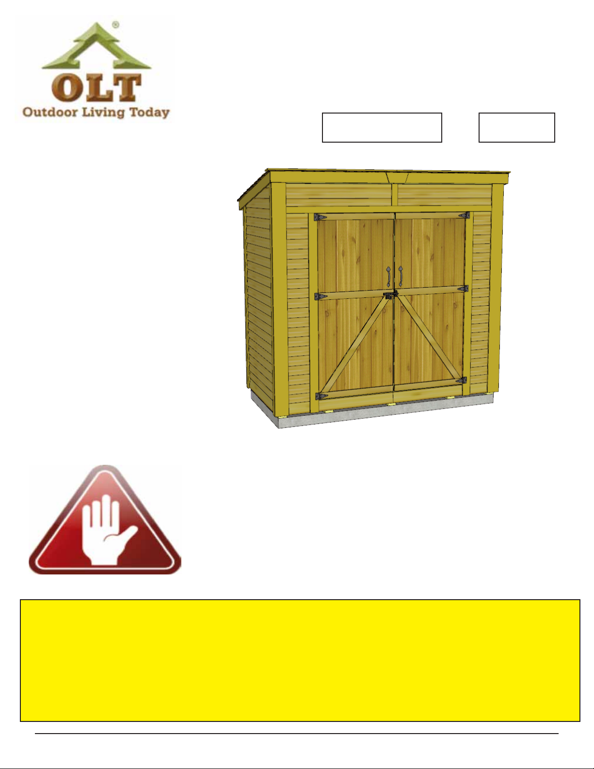
OLT 8x4 SpaceSaver Garden Shed Bevel Model with Plywood... User manual

OLT
OLT Santa Rosa SR812-FJ-Metal User manual

OLT
OLT GS84-SLIDER-PLY-FJ User manual

OLT
OLT CB128-AK-METAL User manual

OLT
OLT Cabana Shed CB128-FJ-METAL User manual

OLT
OLT SpaceSaver SS124-SLIDER-CEDAR-FJ User manual

OLT
OLT SunShed SSGS1216-AK-Ply User manual

OLT
OLT GardenSaver GS124-SLIDER-METAL-FJ User manual

OLT
OLT SpaceSaver SS124-SLIDER-CEDAR-AK User manual

OLT
OLT Muskoka Cabin 9x9 User manual

OLT
OLT SSGS1212 User manual

OLT
OLT 12x12 SpaceMaker Garden Shed User manual

OLT
OLT CB128-SLIDER-METAL-BEV User manual

OLT
OLT GardenSaver GS84D-Plywood User manual

OLT
OLT 12x16 SunShed User manual

OLT
OLT T&G User manual

OLT
OLT CB96-AK-METAL User manual

OLT
OLT SpaceSaver SS124-SLIDER-PLY-FJ User manual

OLT
OLT SunShed SSGS1216-FJ-Cedar User manual

OLT
OLT Studio Garden Shed STU128-FJ-Metal User manual


Popular Garden House manuals by other brands

Mercia Garden Products
Mercia Garden Products 0628LOG181-V4 manual

Lemeks
Lemeks Palmako PA120-5930-6 Assembly, installation and maintenance manual

Rion
Rion Hobby Gardener Assembly instructions

Gartenhaus-King
Gartenhaus-King Valery manual

Select
Select ISAAC E9682 Assembly manual

Mercia Garden Products
Mercia Garden Products 01DTSHPWOR1010DDOW-V4 General instructions

Palmako
Palmako Saale installation manual

Lemeks
Lemeks Palmako Kira EL16-3623 Assembly, installation and maintenance manual

Mercia Garden Products
Mercia Garden Products 0644LOG186-V4 General instructions

Palmako
Palmako Roger FR44-5953-2 installation manual

Mercia Garden Products
Mercia Garden Products 03DTSHHP1206HGD4MW-V1 General instructions

Pergola kits USA
Pergola kits USA PREMIUM VINYL PAVILION Assembly manual

G21
G21 Boston 882 manual

Lemeks
Lemeks Palmako Grace PM56-4529 Assembly, installation and maintenance manual

Mercia Garden Products
Mercia Garden Products 03WES0808-V1 General instructions

Shire
Shire Salcey Assembly

Mercia Garden Products
Mercia Garden Products 05DTMBPN0503DD-V1 Assembly instructions

Rutland County
Rutland County Burley 6ft Assembly instructions