manuals.online logo
Brands
  1. Home
  2. •
  3. Brands
  4. •
  5. olympia electronics
  6. •
  7. Thermostat
  8. •
  9. olympia electronics BS-816 User manual

olympia electronics BS-816 User manual

Page 1 from 4 940817000_09_002
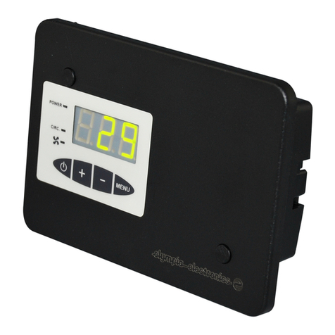
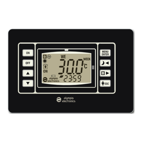
BS-816 and BS-817
PROGRAMMABLE DIGITAL ROOM THERMOSTATS
The digital programmable thermostats are the new advanced
products of Olympia Electronics, in the room temperature control
field. Their smart and appealing design along with high quality makes
these thermostats suitable for virtually any installation and demand.
1. CHARACTERISTICS
Two models are available in this series. The BS-816 thermostat with
one output relay used for connecting a burner and the BS-817
thermostat with 2 output relays used for connecting a circulator and a
burner. Both models have a graphical LCD display and control panel.
The control of the temperature can be done either manually or
automatically on a daily or weekly basis. For the automatic control of
the temperature the thermostat can be programmed via a very user
friendly menu in the English language. Up-to 10 different variations
per day with an resolution of a quarter of an hour can be
programmed into both models.
The thermostats have cooling and heating mode capabilities as well
as an adjustable differential from 0,2 oC to 4 oC. The adjustable
temperature scale is 5 oC to 30 oC, with 0,1 oC resolutions. Also they
incorporate automatic defrost operations and timer functions that
count the precise operating time of the burner. The graphical
display shows useful information regarding the operation mode, the
time which is shown is analogue and digital form and the temperature
of the area.
The clock is retained even if the thermostat is not powered from the
mains power supply, for more than 5 years. All programs are stored
in a special memory chip that retains data even without any power.
2. MOUNTING AND INSTALLATION
The mounting of the thermostat is accomplished using the screws
and plugs included in the packaging. It has 3 mounting holes that can
be accessed by removing the retaining screw that can found on the
bottom side of the thermostat.
During the mounting and installation procedure, the mains
power supply must be isolated. The thermostat must be placed
at a height of about 1,5mm and away from drafts (i.e. doors that
open often), radiator units and in general, all electrical
appliances that produce heat. We should also avoid mounting
the thermostat on exterior walls if it possible.
The various connections done on the thermostats terminal block are
shown in the diagram below.
Mounting points
To burner
To burner
Mounting points
3. BASIC OPERATIONS
3.1. HEATING MODE
When the temperature of the surrounding reaches the desired
temperature the thermostat stops the operation of the burner. In
order for the burner to begin its operation, the temperature must drop
below the desired temperature minus the degrees of the differential.
For example: If the differential is set to 0,5 oC and the desired
temperature is set to 21,7 oC, then the thermostat stops the circulator
at 21,7 oCand starts at 21,2 oC.
As long as the burner is operating the displays shows the heating
symbol and the control button are lit..
3.2. COOLING MODE
When the temperature of the surrounding reaches the desired
temperature the thermostat starts the operation of the cooling unit. In
order for the cooling unit to stop its operation, the temperature must
rise above the desired temperature plus the degrees of the
differential.
As long as the cooling unit is operating, the display shows the AC
cooling symbol and the control button are lit.
3.3. ANTIFROST OPERATION
Anti-frost operation is an additional operation that only works if the
thermostat is in heating mode and is in the OFF position. If the
temperature of the surroundings reaches below 6 oC, then the
thermostat automatically starts the burner. The burner operates as
long as the temperature is below 6 oC. The display shows the
indication DEFROST. Using this method, the thermostat protects the
installation from freezing.
4. INDICATIONS AND CONTROLS
SUNDAY
Page 2 from 4 940817000_09_002
4.1. CONTROLS
The control key pad of the thermostat consists of 6 keys as shown in
the diagram below. Various functions are executed by pressing the
keys.
4.2. GRAPHICAL DISPLAY
The display shows numerous symbols and messages used to
interact with the user. The diagram below shows all existing symbols.
DEFROST
SUNDAY
4.3. DEFAULT SCREEN
When the thermostat is in operation mode ON, the screen shows
some permanent indications such as, a big analog clock with the
current time, the current temperature, the desired temperature (top
right corner), whereas in the bottom side we can see a digital clock,
the day of the week or the present state of the thermostat.
SUNDAY
5. FAST KEY OPERATIONS
From the default screen we can do some fast key operations in order
to control or change the operation status of the thermostat.
5.1. ON-OFF OPERATION
Press the key (ΟΝ/OFF), in order to start or stop the operation of
the thermostat. The key has a toggle effect and the display will show
ON or OFF respectively.
When the thermostat is OFF, then no manual or automatic
operations can take place apart from the anti-frost function.
5.2. DAILY PROGRAM INSPECTION
Use this function to inspect the automatic program that is stored in
memory. To enter this function, press the ESC button. The function
only operates if the thermostat is set to operate in daily or weekly
programming mode in either heating or cooling mode and it’s sate of
operation is ON.Changes to the program cannot be made using this
function. To return to the main display screen press the ESC button
again.
5.3. INTERVENING DURING THE EXECUTION OF AN
AUTOMATIC PROGRAM
The function only operates if the thermostat is set to operate in daily
or weekly programming mode in either heating or cooling mode and
it’s sate of operation is ON
Press the keys or to change the setting of the desired
temperature according to which the thermostat will continue to
operate. As long as the intervention is active a symbol in the form of
a hand is shown on the display. The intervention is automatically
cancelled after 4 hours or if the key is pressed.
5.4. ON-OFF BOILER OPERATION
This function is only available on BS-817 thermostats.
Press the key (B), in order to start the operation of the boiler. To
stop the boiler press the same key once more.
When the boiler is operating the indication symbol “B” is shown on
the screen.
6. THERMOSTAT SETTINGS
While in the default screen press the ENTER key in order to enter the
SETTINGS screen. This screen contains many options that are used
to configure the desired operations of the thermostat.
7. «SETTINGS SCREEN»
Select using the keys and and confirm selection be pressing the
key ENTER. To return to the default screen press the ESC key.
7.1. ADJUSTMENTS
A detailed description is done in the section ADJUSTMENTS
SCREEN
7.2. BOILER TIME
This selection is only available only on BS-817.
In this screen we can adjust the time of the semiautomatic operation
of the Boiler. This setting accepts values from 20 minutes to 24
hours. With the and keys adjust the minutes whereas with the
key adjust the hours. Press the key to reset the setting.
The time set is valid only for one time operation. In order for the
boiler to operate again in semiautomatic mode we must set this time
again.
If the time is set to 00:00, then the Boiler operates only manually.
With the ENTER key confirm the setting and return to the SETTINGS
screen.
7.3. TIME COUNTER
In this screen we can see the time counter.
The hour counter is used to track the exact operating time of the
burner. This counter has a precision of 1 minute. The display shows
the current status of the counter in the format (DAYS, HOURS and
MINUTES). Press the to reset the time counter.
7.4. TEMPERATURE INSPECT
The function only operates if the thermostat is set to operate in daily
or weekly programming mode in either heating or cooling mode.
If a daily program has been chosen then the display shows the graph
of the current daily program.
If a weekly program has been chosen then the display shows the
days of the week. Select the day in order for the graph to be shown.
In this way we can select to see the program for each day
individually.
This function is only for inspection purposes and cannot be used to
alter the programs.
8. ADJUSTMENT SCREEN
Select using the keys and and confirm the selection be pressing
the ENTER key. To exit to the default screen press the ESC key.
8.1. “CLOCK” ADJUSTMENT
In this screen we can adjust the current time.
Using the and keys we can adjust the time in 30 seconds
intervals whereas with the keys and we can adjust the time with
30 minute intervals
With the ENTER key we confirm the setting and return to the
ADJUSTMENTS screen.
ON / OFF
Manual Temperature
Selection
Shows the current
daily program
(if available)
Auto program intervention indicator
Desired temperature
Real temperature
Thermostat state
Heating mode indicator
(In cooling mode “AC” is shown)
Anti-frost operation
Manual Temperature Selection
Activates or deactivates the boiler
(only on BS-817)
Enters the menu
OPTIONS
Boiler operation
indicator (only on BS-817)
Digital clock
Analog Clock
Information
Page 3 from 4 940817000_09_002
8.2. “DAY OF WEEK” ADJUSTMENT
In this screen we can adjust the current day.
Select the desired day of the week using the keys and and .
With the ENTER key we confirm the setting and return to the
ADJUSTMENTS screen.
8.3. “DIFFERENTIAL”ADJUSTMENT
In this page we can adjust the differential of the thermostat according
to which all automatic and manual programs are executed.
With the keys and adjust the differential from 0,2 oC to 4 oC,
with 0,1 oC resolution.
With the ENTER key we confirm the setting and return to the
ADJUSTMENTS screen.
8.4. FACTORY PRESETS
This screen has two selections.
8.4.1. 21 DEG. CONTINUOUS
This preset, if selected stores in the thermostats program memory a
predefined operation program where the desired temperature is kept
constant at 21 oC all days of the week.
With the ENTER key we confirm the setting and return to the
ADJUSTMENTS screen
8.4.2. 21 DEGREES WEEKLY
This preset is shown only if weekly programming has been selected.
A preset program is stored into memory according to which the
adjusted temperature is 21 oC, from Monday through Friday and from
6:30AM to 15:30PM. The rest of the hours and on the Weekend the
temperature is set to 0 oC.
With the ENTER key we confirm the setting and return to the
ADJUSTMENTS screen
8.5. OPERATION MODE
In this screen we can select the mode of operation. 6 modes are
available.
With the ENTER key confirm the selection and return to the
ADJUSTMENTS screen
8.5.1. MANUAL HEAT
The thermostat operates in heating mode. The desired temperature
is set manually using the keyand in the default screen.
8.5.2. DAILY HEAT
The thermostat executes a daily heating program.
8.5.3. WEEKLY HEAT
The thermostat executes a weekly program that consists of
subprograms for every day of the week.
8.5.4. MANUAL COOL
(The same as in par. 8.5.1., but for cooling)
8.5.5. DAILY COOL
(The same as in par. 8.5.2., but for cooling)
8.5.6. WEEKLY COOL
(The same as par. 8.5.3., but for cooling)
8.6. PROGRAM
This option is available only if we previously have selected one of the
modes mentioned in paragraphs 8.5.2 or 8.5.5, for daily operation or
8.5.3 or 8.5.6, for weekly operation.
With the ENTER key confirm the selection.
8.6.1. DAILY PROGRAMMING
If Daily mode has been previously selected then the display shows
the daily programming where the daily program can be designed.
8.6.2. WEEKLY PROGRAMMING
If weekly mode has been previously selected, the display shows the
days of the week. Select the desired day using the keys and and
confirm by pressing ENTER, in order for the programming screen for
the selected day to appear. With this method you can design a
different program for each day of the week.
9. DESIGNING A PROGRAM
Execution of a daily of weekly program means that the thermostat
will be ON and the temperature will follow the pre-designed plan. Up-
to 10 different temperature variations can be programmed in a 24
hour day cycle.
In the top right corner you can see the desired temperature whereas
in the top left corner you can see the time for this temperature. This
largest portion of the screen shows the design field.
The horizontal axis shows the time scale from 0 to 24, whereas the
vertical axis shows the temperature from 5 to 30 oC.
The design is done using a cursor as shown in the diagram.
The cursor shows that at the time 16:15 the desired temperature is
21,0 oC. With the keys and you can move the cursor
horizontally, while simultaneously you can view the time and the
temperature for that specific point where the cursor is.
On the right side of the screen you can see the indication “Μ3” which
shows how many temperature variations are in the program. If we
design a new program we must first erase the old program.
With the key move the cursor to the time 00:00. Press the ENTER,
key for the desired temperature to become 0,0 oC. Press the ESC
key and the cursor will change shape and become “=”. Now with the
key move the value 0,0 oC up-to the time 23:45. Press the ESC
key in order for the cursor to change to its original shape and then
using the key move the cursor to the time 00:00.
Now the design field is empty and the cursor is in the time 00:00,
where the desired temperature is 0,0 oC.
We will design a program where for the time 00:00 to 06:30 the
desired temperature will be 18 oC, and from 06:30 to 08:00 will be 21
oC, from 08:00 έως τις 16:30 will be 18 oC, from 16:30 to 23:00 will be
21 oC and finally from 23:00 to 24:00 will be 18 oC.
With the keys (and ) adjust the temperature setting until is
becomes 18 oC.
Press the ESC,the cursor will become “=”. With the keys and 
move the cursor and carry the same temperature up-to the time
06:15.
Observe that in order to set 18 oC, from 00:00 to 06:30, in reality
we moved the cursor up-to 06:15. This is done because the
design field is divided into 96 sections (96 quarters of an hour).
The first section starts from 00:00 and ends at 00:15, the second
section starts at 00:15 and ends at 00:30 and so on. In this way,
in order to select the second section we move the cursor to
00:15 and not 00:30.
Next, using the keys and adjust the temperature setting until is
shows 21 oC and with the key move this value until the time 07:45.
Next, using the keys and adjust the temperature setting until is
shows 18 oC and with the key move this value until the time 16:15.
Page 4 from 4 940817000_09_002
Next, using the keys and adjust the temperature setting until is
shows 21 oC and with the key move this value until the time 22:45.
Finally, using the keys and adjust the temperature setting until is
shows 18 oC and with the key move this value until the time 23:45.
The programming has finished and as we can see, only 5 of the
available 10 temperature variations have been used. Press the ESC,
for the cursor to return to its normal shape.
Press the , in order to move the cursor to the left side of the screen
with the indication EXIT.
The screen will show the message.
SAVE
PROGRAM DATA
IN MEMORY
WITH ENTER
Press the ENTER,in order to store the program into memory and to
return to ADJUSTMENT screen.
If you do not wish to store the program press ESC to return to
ADJUSTMENT screen.
When the cursor has its normal shape, then by moving it over a
specific quarter section we can adjust the temperature of that
section.
10. WARNINGS
- Avoid removing the retaining screw that holds the casing.
- Do not use sharp objects on the screen and the keys (risk of
electric shock).
- Clean the screen with a soft and dry cloth.
TECHNICAL CHARACTERISTICS
Model
BS-816
BS-817
Operation voltage
220-240V AC / 50-60 Hz
Maximum Consumption
4 VA
Differential
0,2 to 4,0 oC with 0,1 oC intervals
Temperature adjustment
5 to 30 oC
Voltage free relay contacts
Relay
230VAC/8A
(resistive load)
2 Relays
230VAC/8A
(resistive load)
Burner Relay indicators
Illuminated keys and on screen
indications
Boiler Relay indicators
-
On screen
indicators
Heating and Cooling
capability
YES
Constructional material
Bayblend FR3010
Operation temperature
range
0 to 50 oC
Humidity
Up-to 95% relative humidity
Dimensions
110mm x 87mm x 42mm
Weight
200gr
220gr
Degrees of cover protection
IP20
Produced in accordance
with
EN 60730-1, EN 60730-2-9,
EN 61000-6-1, EN 61000-6-3
Guarantee
2 years

This manual suits for next models

1

Other olympia electronics Thermostat manuals

olympia electronics BS-818/KIT User manual

olympia electronics

olympia electronics BS-818/KIT User manual

olympia electronics BS-830 User manual

olympia electronics

olympia electronics BS-830 User manual

olympia electronics BS-900 User manual

olympia electronics

olympia electronics BS-900 User manual

olympia electronics BS-901 User manual

olympia electronics

olympia electronics BS-901 User manual

olympia electronics BS-812/A User manual

olympia electronics

olympia electronics BS-812/A User manual

olympia electronics BS-850/KIT User manual

olympia electronics

olympia electronics BS-850/KIT User manual

olympia electronics BS-850/T User manual

olympia electronics

olympia electronics BS-850/T User manual

olympia electronics BS-821/KIT User manual

olympia electronics

olympia electronics BS-821/KIT User manual

olympia electronics BS-844/2 User manual

olympia electronics

olympia electronics BS-844/2 User manual

olympia electronics BS-812 User manual

olympia electronics

olympia electronics BS-812 User manual

olympia electronics BS-820/KIT User manual

olympia electronics

olympia electronics BS-820/KIT User manual

Popular Thermostat manuals by other brands

TFC RF205-TS instructions

TFC

TFC RF205-TS instructions

Coati 12617 operating instructions

Coati

Coati 12617 operating instructions

Mi-Heat MH7H-EH quick start guide

Mi-Heat

Mi-Heat MH7H-EH quick start guide

Grohe Grohtherm 3000 manual

Grohe

Grohe Grohtherm 3000 manual

Jaga JRT-200 Installation, setup & user manual

Jaga

Jaga JRT-200 Installation, setup & user manual

Stelpro STZB402 Plus user guide

Stelpro

Stelpro STZB402 Plus user guide

Honeywell FocusPRO TH5320R01 operating manual

Honeywell

Honeywell FocusPRO TH5320R01 operating manual

Mi-Heat TH213 manual

Mi-Heat

Mi-Heat TH213 manual

Vemer KEO-B user manual

Vemer

Vemer KEO-B user manual

ritetemp 8029B install guide

ritetemp

ritetemp 8029B install guide

Danfoss DEVI DEVIreg 532 installation guide

Danfoss

Danfoss DEVI DEVIreg 532 installation guide

Hunter Auto Temp 44402 002 Operation manual

Hunter

Hunter Auto Temp 44402 002 Operation manual

OJ Electronics MTC-1991-UFH instructions

OJ Electronics

OJ Electronics MTC-1991-UFH instructions

Siemens RDD310/EH user manual

Siemens

Siemens RDD310/EH user manual

resideo Honeywell Home FocusPRO TH6320WF1005 Wi-Fi... user guide

resideo

resideo Honeywell Home FocusPRO TH6320WF1005 Wi-Fi... user guide

DeDietrich FM52-AD208 manual

DeDietrich

DeDietrich FM52-AD208 manual

Honeywell PROGRAMMABLE THERMOSTAT RTH6350 Quick installation guide

Honeywell

Honeywell PROGRAMMABLE THERMOSTAT RTH6350 Quick installation guide

Myson REMOTE ROOM THERMOSTAT CONTROL installation instructions

Myson

Myson REMOTE ROOM THERMOSTAT CONTROL installation instructions

manuals.online logo
manuals.online logoBrands
  • About & Mission
  • Contact us
  • Privacy Policy
  • Terms and Conditions

Copyright 2025 Manuals.Online. All Rights Reserved.