Page 3 from 11 940821001_09_001
the night program, press the key for
more than 3", the symbol is replaced by
the symbol .
3. Boiler ACTIVATION (available only on
the BS-819/T).
This capability can be executed by pressing
briefly the key, the backlight will be
activated for 2" and the symbol will be
shown on the top left corner of the screen.
The built-in relay will send the command to
the burner. The command will be active for
as long as it has been preselected via the
MENU setting with the indication (Boiler
time), or until the key is pressed again.
. If the preselected Boiler value is 00 then
the deactivation can be done only with the
key. The Boiler command is independent
from the other functions of the device and
can be given even if the thermostat is
deactivated (OFF state). The factory
default Boiler time is 00 minutes.
4. AREA PRESENCE SELECTION ( The
thermostat is in the ON state).
In normal operation, the symbol shows
the presence of people in the area and all
the programs, which ever they are, are
executed normally. In limited absence from
the area(from a few hours to a few days)
there is the capability to execute the
absence program.
If the key is pressed for 3", the backlight
will be activated for 2" and the symbol
will be changed to .This command
superimposes every other program. The
selected temperature is shown on the
screen if any of the keys is
pressed and can’t be changed. The value
can be changed only with the selection
(Absent time) of the MENU. The factory
default setting of this temperature is 16.0
ºC and can be altered from 6.0 to 30.0 ºC.
To deactivate the absence mode, the
key must be pressed for 3", then the
thermostat will continue the execution of
the program that was running before
absence mode was selected.
5. KEYPAD LOCK (in any operation state).
If the keys and are pressed
simultaneously for 3"(first the key and
then the ) ,the screen will show the
message and the keypad is locked.
Page 3 from 11
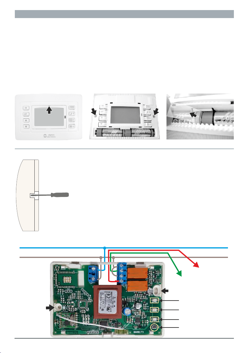
GENERAL
When the plastic battery separator is
remove the unit is automatically activated
and shows all the screen indicators for
1",then the firmware version is shown and
finally the screen enters final operation
status. In the center of the screen we can
see the current temperature. The clock has
the hour 00:00, the date is 1 January
(Friday) 2016 and the thermostat is inactive
(OFF state). In this state the only available
s e l e c t i o n s a r e B o i l e r a c t i v a t i o n
/deactivation (only for BS-821/ΚΙΤ) and
entry to the settings menu. If the key is
pressed momentarily , the screen
illumination will be activated for 2" and the
symbols , and ΜΑΝ will be shown which
are the factory defaults.
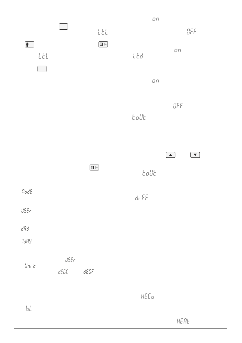
1. ENTERING THE MENU (the thermostat
in the OFF state).
To enter the menu settings press the
button for more than 3".
The screen will be illuminated and will stay
illuminated during all the duration of the
settings Please note that only settings that .
are blinking can be changed To navigate .
through the menu items use the
keys and . To change the value of a
menu item use the keys . Press
the key to accept the change or press
the key to go to the previous state. If no
key is pressed for 2 minutes then the
thermostat returns to normal operation
while saving the changed settings.
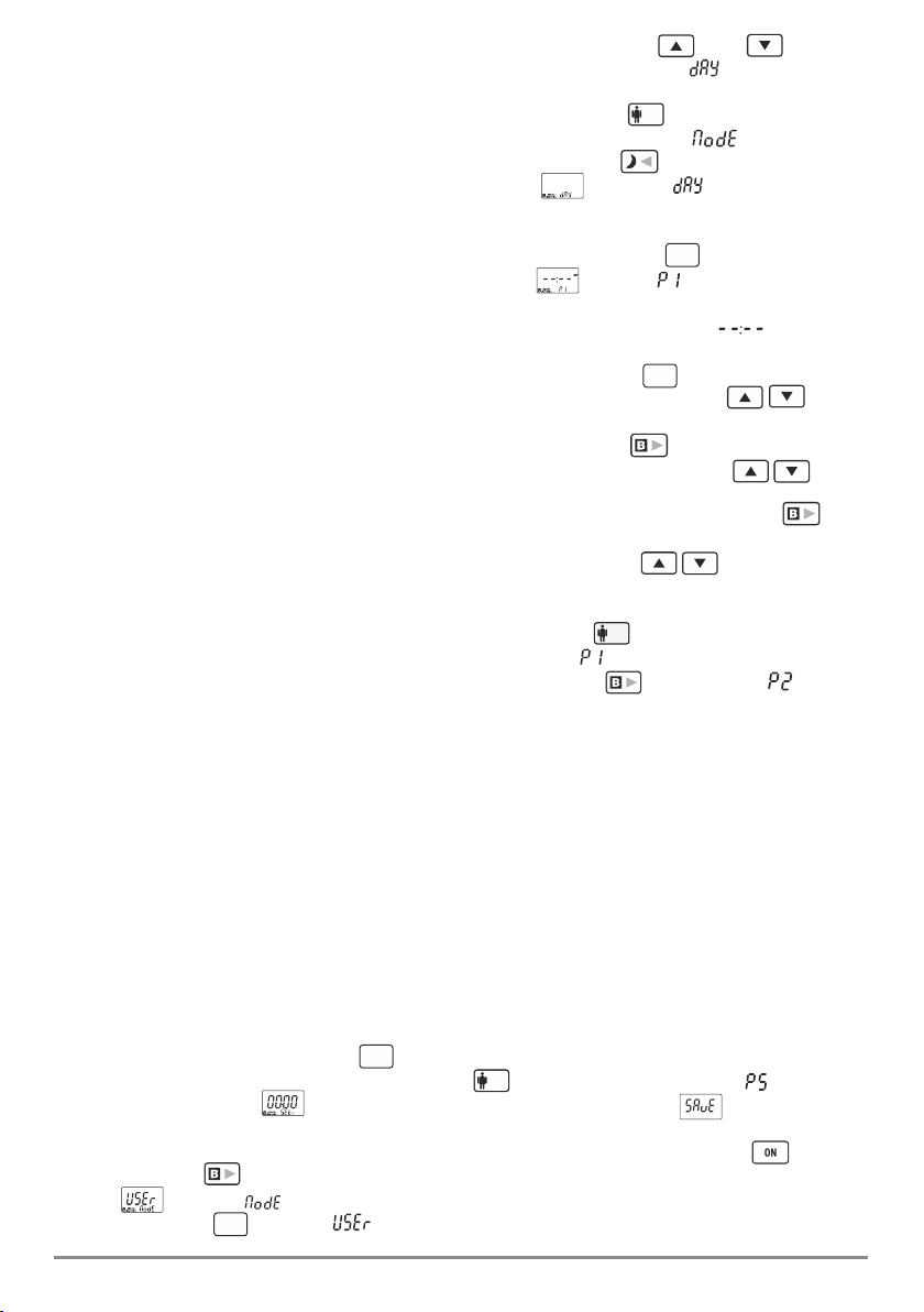
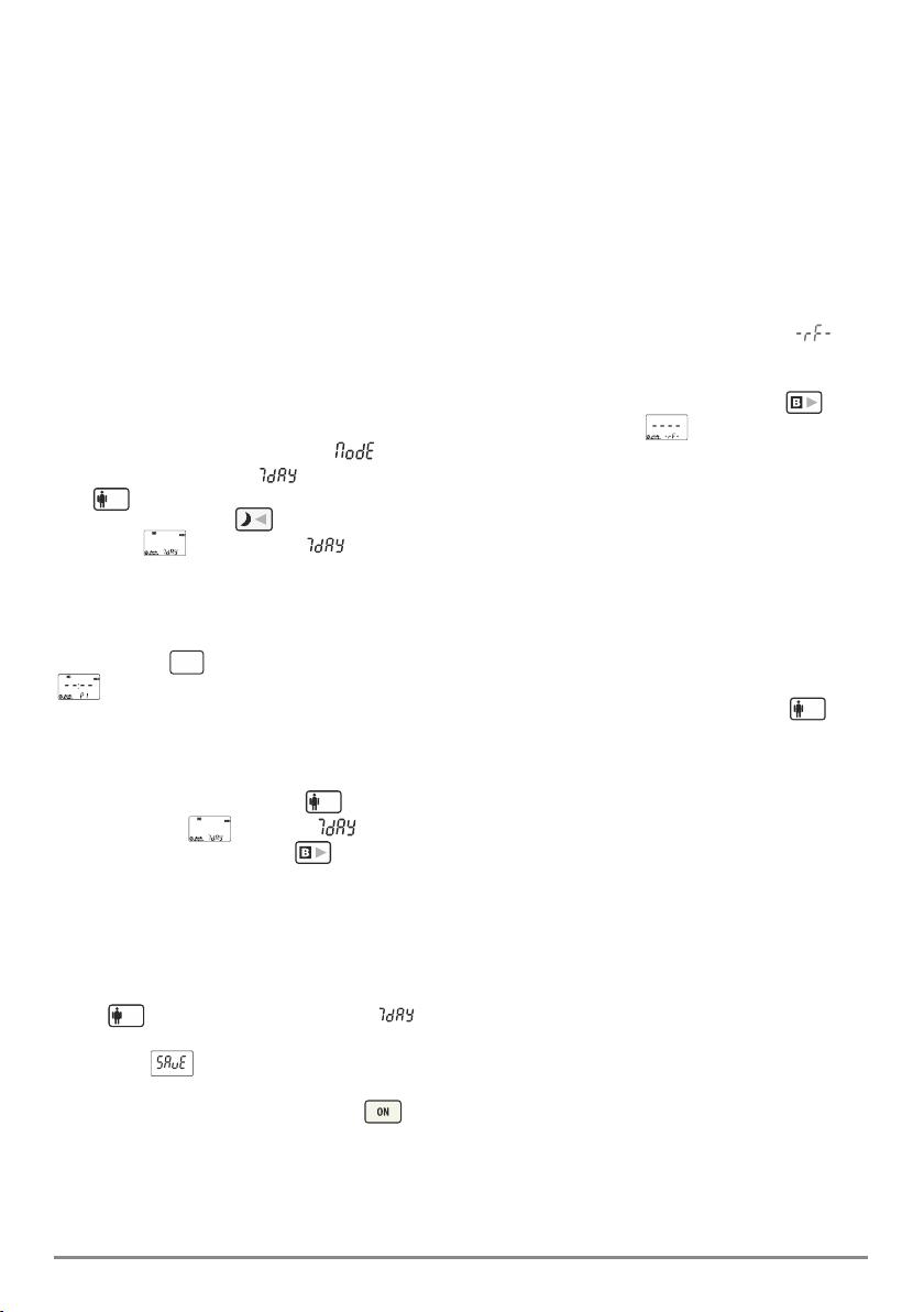
2. SE L E C T I N G D AY OR N I G H T
OPERATION MODE
(the thermostat is in the ON state and in
manual operation).
If the key is pressed for more than 3"
then the indication is deactivated and we
can see the . This means that night
operation mode has been selected. This
selection replaces temporarily the manually
selected temperature for as long as the
night program is active. If one of the
keys is pressed then the set night
program temperature is shown. (this can
be changed from the setting (night) of
the ΜΕΝU). The factory default night
temperature is set to 18.0ºC. To deactivate
MENU
ENTER
ESC
MENU
ENTER
ESC
ESC
MENU
ENTER
MENU
ENTER