6DAc
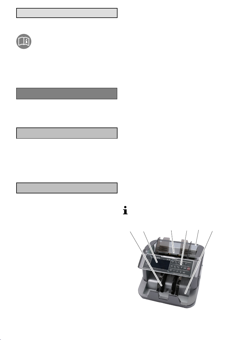
Banknoten einlegen
Das Banknotenzählgerät ist ein Frontlade-Gerät, wo
die Banknoten von der Vorderseite beladen werden.
ÆLegen Sie das Banknotenbündel in das Ein
legefach [3].
ÊDie unterste Banknote des Banknotenbündels wird
in das Banknotenzählgerät eingezogen.
Führen Sie die Zählung für die sichere Er
kennung von kritischen Banknoten von beiden
Seiten durch. Die Sicherheitsmerkmale der Bank
noten befinden sich auf beiden Seiten der Banknote.
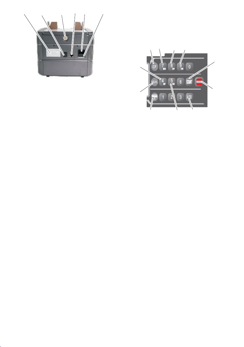
Automatischer/manueller Einzug
Automatischer Einzug:
ÆDrücken Sie die Taste M/A [22].
ÊDer automatische Einzug der Banknoten wird ak
tiviert. Im Display wird AUTO[25] angezeigt.
Manueller Einzug:
ÆDrücken Sie die Taste M/A [22], bis im Display
AUTO [25] erlischt.
ÊDer manuelle Einzug der Banknoten wird aktiviert.
ÆDrücken Sie die Taste RESET [18], um die Zäh
lung zu starten.
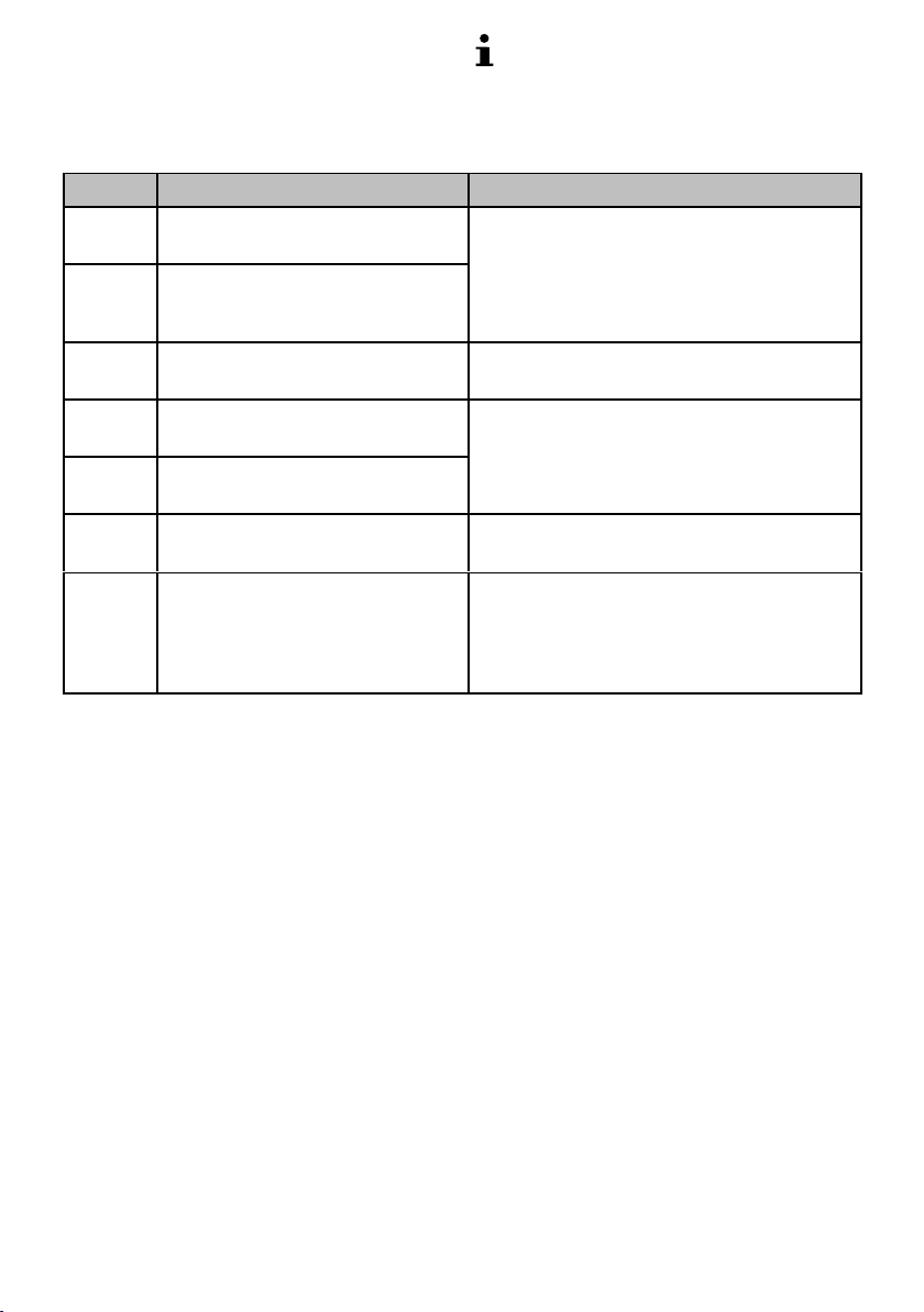
Funktionen
ÆWählen Sie die gewünschte Funktion aus.
Zählen
Bei dieser Funktion wird die Anzahl der Banknoten
und je nach Einstellung der Sensoren auch die Echt
heit geprüft.
Während der Zählung wird die Anzahl der Banknoten
in der oberen Anzeige [24] angezeigt.
Werden die gezählten Banknoten im Ausgabefach [6]
belassen, wird die Zählung fortgesetzt.
Werden die gezählten Banknoten aus dem Aus
gabefach [6] genommen und ein neuer Stapel Bank
noten in das Einlegefach [3] eingelegt, beginnt die
Zählung wieder bei X0.
Die vorherige Zählung der Banknoten wird in der un
teren Anzeige [30] angezeigt.
ÆDrücken Sie die Taste COUNT [17].
ÊDie Banknoten werden ohne Merkmalprüfung (UV,
MG, MT, IR) gezählt und im Ausgabefach [6] abge
legt.
Addieren
Bei dieser Funktion, wird die Zählung weitergeführt,
auch wenn die gezählten Banknoten aus dem Aus
gabefach [6] entnommen wurden und anschließend
neue Banknotenbündel in das Einlegefach [3] gelegt
werden.
Diese Funktion ist besonders geeignet für große
Banknotenbündel oder für gebrauchte oder stark ge
knickten Banknoten. Es können kleinere Banknoten
bündel nacheinander gezählt werden. Das Bank
notenzählgerät führt die Zählung der Banknoten fort.
ÆDrücken Sie die Taste ADD [19].
ÊFunktion Addieren ist aktiviert/deaktiviert. Im Dis
play wird ADD [28] angezeigt.
Bündeln
Bei dieser Funktion stoppt die Zählung, wenn eine
voreingestellte Anzahl von Banknoten gezählt wurde.
Wird das gezählte Banknotenbündel aus dem Aus
gabefach [6] entnommen, springt die obere Anzeige
[24] auf X0 und das nächste Banknotenbündel wird
gezählt.
ÆDrücken Sie die Taste BATCH/C [21].
ÊIm Display wird BAT [27] angezeigt. In der unteren
Anzeige [30] erscheint die voreingestellte Anzahl
100.