Olympia Carrera De Luxe MD User manual

SERVICE MANUAL
Olympia Carrera De Luxe MD
Electronic Typewriter
EDITION 3
JUNE 2009
001-03139-03

Table of Contents
1. Specifications 1-1
・・・・・・・・・・・・・・・・・・・・・・・・・・・・・・・・・・・・・・・・・・・・・・・・・・・
・・・・・・・・・・・・・・・・・・・・・・・・・・・・・・・・・・・・・・・・・・・・・・・・・・・・・・・・・・・・・・・・・・
・・・・・・・・・・・・・・・・・・・・・・・・・・・・・・・・・・・・・・・・・・・・・・・・・・・・・・・・・・・・・・・・・
・・・・・・・・・・・・・・・・・・・・・・・・・・・・・・・・・・・・・・・・・・・・
・・・・・・・・・・・・・・・・・・・・・・・・・・・・・・・・・・・・・・・・・・・・・・・・・・・・・・・・・・・・・・・・・・・・・・・
・・・・・・・・・・・・・・・・・・・・・・・・・・・・・・・・・・・・・・・・・・・・・・・・・・・・・・・・・・・・・・・・・・・
・・・・・・・・・・・・・・・・・・・・・・・・・・・・・・・・・・・・・・・・・・・・・・・・・・・・・・
・・・・・・・・・・・・・・・・・・・・・・・・・・・・・・・・・・・・・
・・・・・・・・・・・・・・・・・・・・・・・・・・・・・・・・・・・・・・・・・・・・・・・・・・・・・・・・・・・・・・・・・・・・・・・・・・
・・・・・・・・・・・・・・・・・・・・・・・・・・・・・・・・・・・・・・・・・・・・・・・・・・・・・・・・・・・・・・・・・・・・・・・・・・・・・・
・・・・・・・・・・・・・・・・・・・・・・・・・・・・・・・・・・・・・・・・・・・・・・・・・・・・・・・・・・・・・・・・・・・・・・・・
・・・・・・・・・・・・・・・・・・・・・・・・・・・・・・・・・・・・・・・・・・・・・・・・・・・・・・・・・・・
・・・・・・・・・・・・・・・・・・・・・・・・・・・・・・・・・・・・・・・・・・・・・・・・・・・・・・・・・・・・・・・・・・・・・・・・・・・・・・・・・・
・・・・・・・・・・・・・・・・・・・・・・・・・・・・・・・・・・・・・・・・・・・・・・・・・・・・・・・・・・・・・・・・・・・・・・・・・
・・・・・・・・・・・・・・・・・・・・・・・・・・・・・・・・・・・
・・・・・・・・・・・・・・・・・・・・・・・・・・・・・・・・・・・・・・・・・・・・・・・・・・・・・・・・・・・
・・・・・・・・・・・・・・・・・・・・・・・・・・・・・・・・・・・・・・・・・・・・・・・・・・・・・・・・・・・・・・・・・・・・・・・
・・・・・・・・・・・・・・・・・・・・・・・・・・・・・・・・・・・・・・・・・・・・・・・・・・・・・・・・・・・・・・・・
・・・・・・・・・・・・・・・・・・・・・・・・・・・・・・・・・・・・・・・・・・・・
・・・・・・・・・・・・・・・・・
・・・・・・・・・・・・・・・・・・・・・・・・・・・・・・・・・・・・・・・・
・・・・・・・・・・・・・・・・・・・・・・・・・・・・・・・・・・・・・・・・・・・・・・・・・・・・・・・・・・・・・・・・・・
・・・・・・・・・・・・・・・・・・・・・・・・・・・・・・・・・・・・・・・・・・・・・・・・・・
・・・・・・・・・・・・・・・・・・・・・・・・・・・・・・・・・・・・・・・・・・
・・・・・・・・・・・・・・・・・・・・・・・・・・・・・・・・・・・・・・・・・・・・・・・・・・・・・・
・・・・・・・・・・・・・・・・・・・・・・・・・・・・・・・・・・・・・・・・・・・・・・
・・・・・・・・・・・・・・・・・・・・・・・・・・・
・・・・・・・・・・・・・・・・・・・・・・・・・・・・・・・・・・・・・・・・・・・・・・・・・
・・・・・・・・・・・・・・・・・・・・・・・・・・・・・・・・・・・・・・・・・・・・・・・・・・・・・・・・・
・・・・・・・・・・・・・・・・・・・・・・・・・・・・・・・・・・・・
・・・・・・・・・・・・・・・・・・・・・・・・・・・・・・・・・・・・・・・・・・・・・・・・・・・・・・・・・・・・・・・・・・・・・・・・・・・・・・・
・・・・・・・・・・・・・・・・・・・・・・・・・・・・・・・・・・・・・・・・・・・・・・・・・・・・・・・・・・・・・・
・・・・・・・・・・・・・・・・・・・・・・・・・・・・・・・・・・・・・・・・・・・・・・・・・・・・・・・・・・・・・
・・・・・・・・・・・・・・・・・・・・・・・・・・・・・・・・・・・・・・・・・・・・・・・・・・
・・・・・・・・・・・・・・・・・・・・・・・・・・・・・・・・・・・・・・・・・・・・・・・・・・・・・・・
・・・・・・・・・・・・・・・・・・・・・・・・・・・・・・・・・・・・・・・・・・・・・・・・・・・・・・・・・・・・・・・・
・・・・・・・・・・・・・・・・・・・・・・・・・・・・・・・・・・・・・・・・・・・・・・・・・・・・・・・・・・・・・・・・・・・・・・・・
・・・・・・・・・・・・・・・・・・・・・・・・・・・・・・・・・・・・・・・・・・・・・・・・・・・・・・・・・・・・・・・・・・・・・・・・・
1.1 General Specifications 1-1
1.2 Hardware Specifications 1-2
2. General Construction 2-1
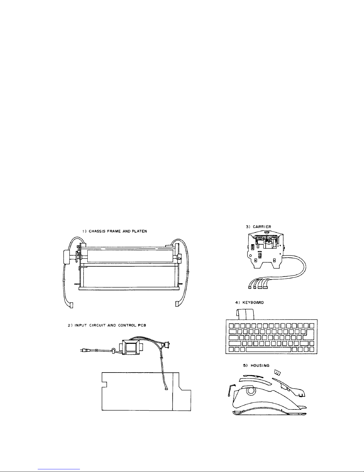
2.1 Basic Assemblies 2-1
2.2 Electronic Assemblies 2-2
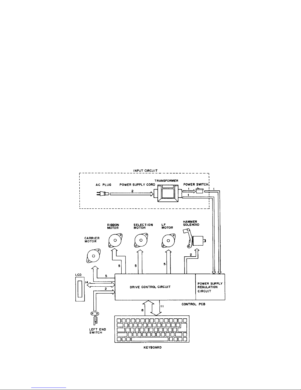
2.3 Components and General Operation 2-3
3. Circuit Diagrams and Layouts 3-1
3.1 Power Supply 3-1
3.2 Keyboard 3-3
3.3 Motor Diagrams 3-5
3.4 Solenoid and Switch Diagrams 3-7
3.5 LCD 3-8
3.6 Control PCB 3-10
4. Adjustment and Measurements 4-1
4.1 General Adjustment Procedure 4-1
4.2 Self Printing Test 4-1
4.3 Setting Adjustment Mode 4-2
4.3.1 Carrier Home Position Adjustment Mode 4-2
4.3.2 Selection Motor Home Position and Hammer Position Adjustment Mode 4-2
4.3.3 Carrier and Platen Position Adjustment Mode 4-2
4.4 Adjustment Procedure 4-3
4.4.1 Carrier Home Position Adjustment 4-3
4.4.2 Selection Motor Home Position Adjustment 4-5
4.4.3 Hammer Position Adjustment 4-7
4.4.4 Carrier and Platen Position Adjustment 4-8
4.4.5 Correction Tape Lift and Ribbon Tape Position Adjustment 4-10
4.4.6 Carrier Drive Tension Adjustment 4-12
4.4.7 Line Locator Adjustment 4-13
5. Disassembly and Reassembly 5-1
5.1 Housing 5-1
5.2 Keyboard and Control PCB 5-4
5.3 Chassis Frame and Platen 5-12
5.4 LF (Line Feed) Motor and Carrier Drive 5-14
5.5 Cassette Base and Ribbon Drive 5-17
5.6 Selection and Hammer 5-20
5.7 Power Supply 5-23
5.8 Wire Routing 5-25
i

ii
・・・・・・・・・・・・・・・・・・・・・・・・・・・・・・・・・・・・・・・・・
・・・・・・・・・・・・・・・・・・・・・・・・・・・・・・・・・・・・・・・・・・・・・・・・・・・・・・・・・・・・・・・・・・・・・・・・・・・・
・・・・・・・・・・・・・・・・・・・・・・・・・・・・・・・・・・・・・・・・・・・・・・・・・・・・・・・・・・・・・・・・・・・・・・・・・・・・・・
・・・・・・・・・・・・・・・・・・・・・・・・・・・・・・・・・・・・・・・・・・・・・・・・・・・・・・・・・・・
・・・・・・・・・・・・・・・・・・・・・・・・・・・・・・・・・・・・・・・・・・・・・・・・・
6. Lubrication and Cleaning 6-1
6.1 Lubrication 6-1
6.2 Cleaning 6-4
7. Tools 7-1
8. Troubleshooting 8-1

1. Specifications
1.1 General Specifications
Print mode
Printing mechanism: Printwheel (no rubber); all characters
Number of characters: 100 characters
Line spacing: Single-line spacing (6 LPI (lines per inch))
1-1/2-line spacing (4 LPI)
Double-line spacing (3 LPI)
Print pitch: Pica:90 characters per line
Elite:108 characters per line
Micro:135 characters per line
Printing width: 9.0" (229.0 mm)
Paper width: 13.0" (330.0 mm)
Printing speed: 11 CPS (characters per second)
Key buffer: 30 characters (maximum)
Number of copies: 1 original + 2 copies
Printing impression control: Low/medium/high, or adjustable (by engineer) using a short jumper
(SW202) on the control PCB
Preset margins Pica:Left - 10, right - 75
(factory settings): Elite:Left - 12, right - 90
Micro:Left - 15, right - 113
Tab settings: 16 tabs (can be set/released without selecting a position)
Correction memory: Full-line
Ribbon cassette:
Correctable ribbon cassette Approximately 50,000 characters/cassette;
(standard): 0.31" (8.0 mm) × approximately 169.5 yards (155.0 m)
Correction tape:
Lift-off correction tape Approximately 1,700 characters
(standard):
1-1

1.2 Hardware Specifications
Power supply
Primary circuit voltage: 100V AC ±10% 50/60Hz
120V AC ±10% 50/60Hz
230V AC ±10% 50/60Hz
Secondary circuit voltage: +15V DC (+VH) unstable voltage (with DC 1.5A load)
+5V DC (+VC) stable voltage
Power consumption: Under rated load: Approximately 4W (standby)
Approximately 18W (operation)
Under no load: 2W (power off)
Fuses
Secondary circuit: 3.0A 250V (100/120/230V, AC 50/60Hz)
Built into transformer: Thermal fuse (+266ºF (+130ºC 12A))
Stepping motors
Carrier motor:
Step angle: 15º(24 steps/rotation (1/2 step/character))
Resistance per coil: 27 ohm/coil (Matsushita) 27SIN18E8NA
25 ohm/coil (NMB-MAT) PM25L-024-NAC3 (Changed in Sep.
2007)
Drive voltage: +VH
Selection motor:
Step angle: 15º(24 steps/rotation (2 steps/character))
Resistance per coil: 42 ohm/coil (Matsushita) 27SIN18E9ND
42 ohm/coil (NMB-MAT) PM25L-024-NAB7 (Changed in Sep. 2007)
Drive voltage: +VH
LF (line feed) motor:
Step angle: 15º (24 steps/rotation)
Resistance per coil: 45 ohm/coil (Matsushita) 27SIN18ECNW
42 ohm/coil (NMB-MAT) PM25L-024-NAC0 (Changed in Sep.
2007)
Drive voltage: +VH
Ribbon motor:
Step angle: 15º(24 steps/rotation)
Resistance per coil: 42 ohm/coil (Matsushita) 27SIN18E9NE
42 ohm/coil (NMB-MAT) PM25L-024-NAB8 (Changed in Sep. 2007)
Drive voltage: +VH
Keyboard
Keyboard style: Rubber contact switches (8 × 8 keyboard matrix)
Number of printing keys: 45 keys
Number of function keys: 17 keys
Key rollover system: 2-key rollover
Repeat function: Time delay method
1-2

LCD (liquid crystal display)
Type: The Epson (ECM-A0697) type LCD or JIC (MSBZ9129) type LCD is
used; furthermore, different versions are provided for use with
USA/Europe keyboards, Eastern Europe keyboards, and with
Thailand keyboards.
Number of display characters: 20 characters × 2 lines (100 columns × 16 rows)
Drive duty: 1/16 duty
Character configuration: 5 columns × 8 rows (including the cursor)
Control PCB assembly
Original version:
CPU(IC201): Toshiba TMP90C141N (CMOS) is the 8-bit microprocessor
ROM (IC203): 512K bit or 1M bit EP ROM from SGS, Sony, National
Semiconductor, etc.
The ROM capacity depends on the spelling check function and on
differences in the keyboard arrangements.
4M bit mask ROM can also be used (contains the spelling check
program and dictionary).
ROM (IC204): 2M bit mask ROM (contains the spelling check dictionary).
Gate array (IC202): The NEC uPD65006CW-A19 or uPD65006CW-A22 is a
semi-custom CMOS gate array in which each gate has been
designed for this typewriter.
RAM (IC205): 256K bit or 1M bit CMOS static RAM (manufactured by NEC and
others), or equivalent.
2nd (second) version:
CPU(IC201): NEC UPD78F1174 or UPD78F1178 is the 16-bit microprocessor.
The CPU builds in FROM and RAM.
The program is written in at FROM and memory does the store in
RAM.
UPD78F1174: 128K byte-FROM, 8K byte-RAM
UPD78F1178: 512K byte-FROM, 30Kbyte-RAM
RAM (IC203): 128K bit CMOS static RAM (manufactured by Renesas and others),
or equivalent.
Prepares the PCBs of original version and 2nd version
This manual describes the control PCB of Toshiba CPU (TMP90C141N) at original version, and the
control PCB of NEC CPU (UPD78F1174/1178) describes it at 2nd version.
Major specification:
Original version 2nd version
Control PCB Artwork No. 999-32300 999-35810
CPU (IC201) Toshiba TMP90C141N NEC UPD78F1174/1178
Control PCB size (W × D) 11 × 4.34" (277 × 110mm) 7.49 × 4.34" (190 × 110mm)
Effective production Up to Aug. 2008 From Aug. 2008
1-3

Battery
Type: Model CR2032 lithium (Li/MnO2) battery with tab (manufactured by
Matsushita, Sanyo, Sony, etc.), or equivalent.
Voltage: +3.0V (210 mAh)
Size: 0.85" (21.5 mm) diameter × 0.15" (3.8 mm)
Applications: Store memory backup
Operational life: Five years at operating temperature
Replacement and disposal for the battery
Note:
Servicing to be performed only by manufacture's qualified personal.
Caution:
Do not incinerate.
1-4
Environmental conditions
Operating temperature: +41ºF to +95ºF (+5ºC to +35ºC)
Storage temperature: -13ºF to +140ºF (-25ºC to +60ºC)
Relative humidity: 90% (+140ºF (+60ºC))
Dimensions
Width: 16.8" (426 mm)
Height: 4.6" (117 mm)
Depth: 14.8" (376 mm)
Weight: 11.6 lbs (5.2 kg), including the keyboard cover
Note:
The nominal specs represent the design specs. All units should approximate these specs -
some will exceed and some may drop slightly below these specs. Limit specs represent the
absolute worst condition that still might be considered acceptable. In no case shall a unit fail to
meet limit specs.

2. General Construction
2.1 Basic Assemblies
This typewriter consists of the following five major assemblies.
1) Chassis frame and platen
This assembly consists of the carrier motor, the LF (line feed) motor, the carrier drive
mechanism, and the platen.
2) Input circuit and control PCB
This assembly consists of the transformer, input circuit, and the control PCB (printed circuit
board).
3) Carrier
This assembly consists of the ribbon feeder, lift mechanism (correction feeder), ribbon motor,
hammer solenoid (printing mechanism), selection mechanism, and left end switch.
4) Keyboard
This assembly consists of the keyboard panel, membrane sheet, keyboard support panel, and
key tops.
5) Housing
This assembly consists of the main cabinet, top cover, paper stand, cord cover, bottom cabinet,
LCD cover, and LCD.
2-1

2.2 Electronic Assemblies
The basic configurations of the electronic assemblies are described below:
1) Input circuit
This assembly supplies voltage through the power cord, transformer, and power switch.
2) Control PCB (power supply smoothing circuit and drive circuit)
In the power supply smoothing circuit AC voltage is transformed into DC voltage. In the drive
circuit, the ICs (such as the CPU and SRAM) and transistors drive and control the stepping
motors, hammer solenoid, etc.
The store data is stored in SRAM.
The LCD displays text and information on functions.
3) Keyboard
The keyboard assembly consists of the keyboard panel, membrane sheet (8 × 8 key matrix),
keyboard support panel, and key tops.
4) Actuator and left end switch
The carrier, platen, selection, and ribbon/correction tape mechanisms are driven by four
stepping motors, while the hammer solenoid (printing mechanism) moves the hammer.
The left end switch detects the carrier home position and reports it to the CPU.
2-2

2.3 Components and General Operation
Original version (Control PCB:Artwork No. 999-32300)
The control PCB includes the CPU (IC201), the gate array (IC202), the EP ROM (IC203)
programmed with the data necessary for typewriter operation, the SRAM (IC205) that holds the
store data, and their peripheral devices. If the unit is equipped with the spelling checker function,
the control PCB is also equipped with a ROM (IC204).
When the power is turned on and the initial operations are completed, the CPU (IC201) begins key
scanning the keyboard through the gate array (IC202). If key input is deemed to have been made,
the CPU (IC201) reads the data concerning the printing impression for that key, the step angle for
the motor, etc., from ROM (IC203). The excitation phasing of the selection motor, carrier motor,
ribbon motor and LF motor is controlled by this data, and the hammer solenoid is turned on.
Block diagram
2-3

2nd version (Control PCB:Artwork No. 999-35810)
The control PCB includes the CPU (IC201), the FROM built-in CPU (IC201) programmed with the
data necessary for typewriter operation, the SRAM (IC203) that holds store data, and their
peripheral devices. If the unit is equipped with the spelling checker function, the CPU (IC201) is
equipped FROM in 512K byte.
When the power is turned on and the initial operations are completed, the CPU (IC201) begins key
scanning the keyboard. If key input is deemed to have been made, the CPU (IC201) reads the
data concerning the printing impression for that key, the step angle for the motor, etc., from FROM
in CPU (IC201). The excitation phasing of the selection motor, carrier motor, ribbon motor and LF
motor is controlled by this data, and the hammer solenoid is turned on.
Block diagram
2-4

3. Circuit Diagrams and Layouts
3.1 Power Supply
Power supply assembly diagram for Original version (Control PCB:Artwork No. 999-32300)
Connection diagram for Original version (Control PCB:Artwork No. 999-32300)
3-1

Power supply assembly diagram for 2nd version (Control PCB:Artwork No. 999-35810)
Connection diagram for 2nd version (Control PCB:Artwork No. 999-35810)
3-2

3.2 Keyboard
Keyboard layout Keyboard contact layout (membrane sheet)
3-3

Keyboard contact diagram (keyboard matrix)
3-4

3.3 Motor Diagrams
Carrier motor
Original version (Control PCB:Artwork No. 999-32300) + Matsushita motor
2nd version (Control PCB:Artwork No. 999-35810) + NMB-MAT motor
Selection motor
Original version (Control PCB:Artwork No. 999-32300) + Matsushita motor
2nd version (Control PCB:Artwork No. 999-35810) + NMB-MAT motor
3-5

LF motor
Original version (Control PCB:Artwork No. 999-32300) + Matsushita motor
2nd version (Control PCB:Artwork No. 999-35810) + NMB-MAT motor
Ribbon motor
Original version (Control PCB:Artwork No. 999-32300) + Matsushita motor
2nd version (Control PCB:Artwork No. 999-35810) + NMB-MAT motor
3-6

3.4 Solenoid and Switch Diagrams
Hammer solenoid
Original version (Control PCB:Artwork No. 999-32300)
2nd version (Control PCB:Artwork No. 999-35810)
Left end switch
Original version (Control PCB:Artwork No. 999-32300)
2nd version (Control PCB:Artwork No. 999-35810)
3-7

3.5 LCD
LCD layout
Epson (ECM-A0697) type
JIC (MSBZ9129) type
3-8

LCD block diagram
Epson (ECM-A0697) type
JIC (MSBZ9129) type
3-9
Table of contents
Other Olympia Typewriter manuals