9
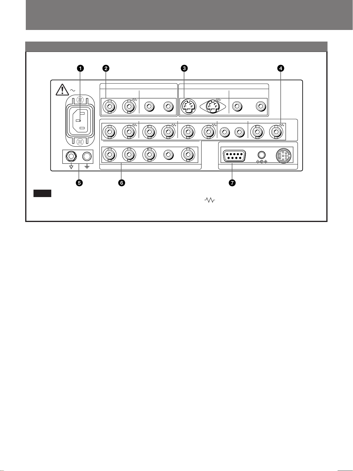
4RGB/COMPONENT A connectors
RGB signal or component signal input connectors and
their loop-through output connectors.
To monitor the input signal fed through these
connectors, press the RGB/COMPONENT A select
button (light on) on the front panel.
Then select one out of four items in the RGB A
SYSTEM menu to set the RGB or COMP (component)
signal and the INT SYNC (internal sync) or EXT SYNC
(external sync) signal.
For the operation through the menus, see pages 12 to
15.
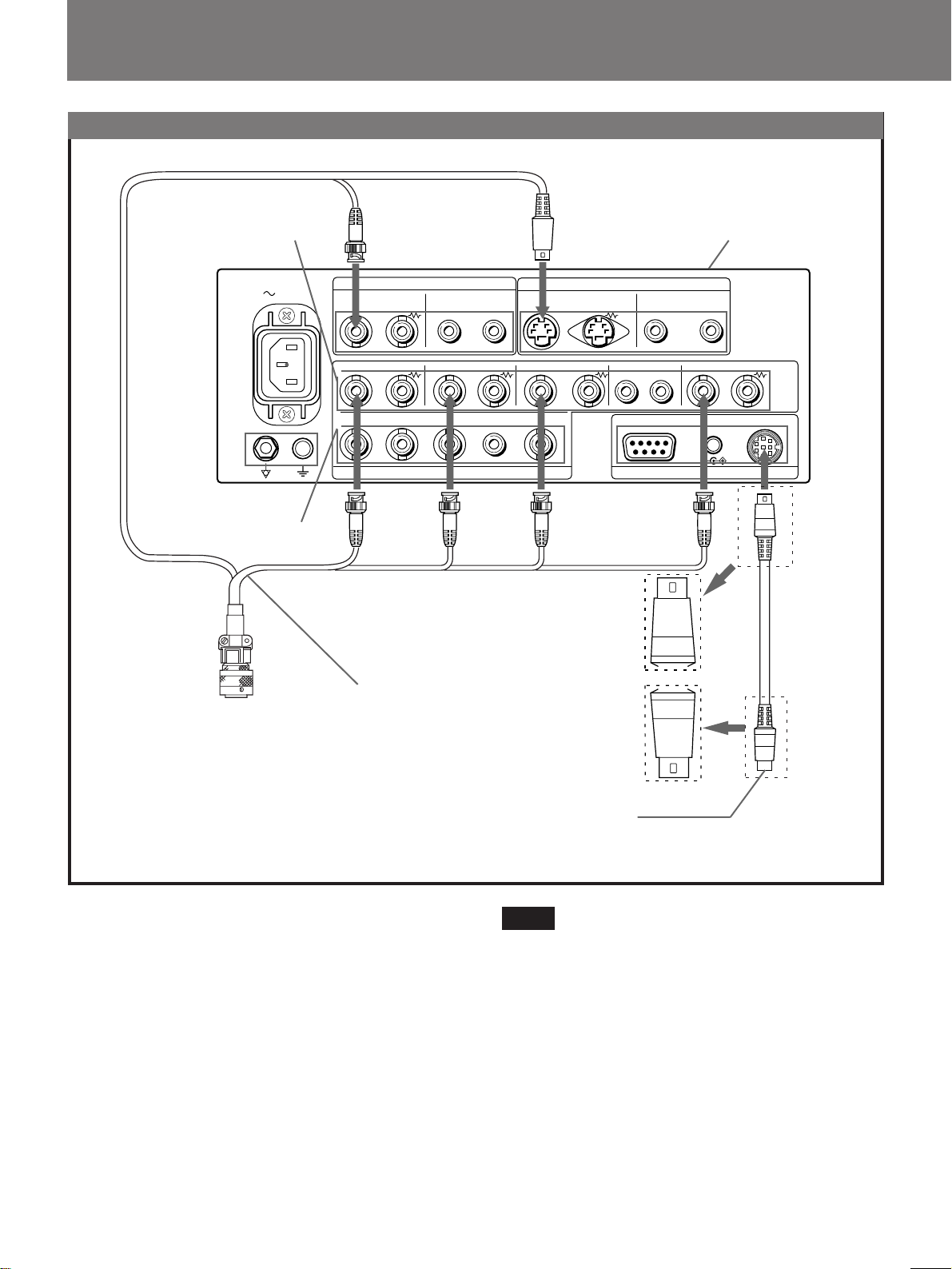
R/R-Y IN, G/Y IN, B/B-Y IN (BNC)
When “RGB-INT SYNC” or “COMP-INT SYNC” is
selected in the RGB A SYSTEM menu, the monitor
operates on the sync signal from the G/Y channel.
To monitor the RGB signal
Connect to the analog RGB signal output connectors of
the video system center.
To monitor the component signal
Connect to the R-Y/Y/B-Y component signal output
connectors.
R/R-Y OUT, G/Y OUT, B/B-Y OUT (BNC)
Loop-through outputs of the R/R-Y IN, G/Y IN, B/B-Y
IN connectors.
When the cables are connected to these connectors, the
75-ohms termination of the inputs is automatically
released, and the signal inputs to the R/R-Y IN, G/Y IN,
B/B-Y IN connectors are output from these connectors.
To output the analog RGB signal
Connect to the analog RGB signal input connectors of a
video printer or another monitor.
To output the component signal
Connect to the R-Y/Y/B-Y component signal input
connectors.
AUDIO IN (phono jack)
Connect to the audio output connector of video
equipment when the analog RGB or component signal is
input.
AUDIO OUT (phono jack)
Loop-through outputs of the AUDIO IN connector.
EXT SYNC (external sync) IN (BNC)
When this monitor operates on an external sync signal,
connect the signal from a video system center to this
connector.
To use the sync signal fed through this connector, select
“RGB-EXT SYNC” or “COMP-EXT SYNC” in the
RGB A SYSTEM menu.
EXT SYNC (external sync) OUT (BNC)
Loop-through output of the EXT SYNC IN connector.
Connect to the external sync input connector of video
equipment to be synchronized with this monitor.
When the cable is connected to this connector, the
75-ohms termination of the input is released, and the
signal input to the EXT SYNC IN connector is output
from this connector.
5Ground (1/Y) terminal
Connect a GND cable.
6RGB/COMPONENT B connectors
RGB signal or component signal input connectors.
To monitor the input signal fed through these
connectors, press the RGB/COMPONENT B select
button (light on) on the front panel.
Then select one out of four items in the RGB B
SYSTEM menu to set the RGB or COMP (component)
signal and the INT SYNC (internal sync) or EXT SYNC
(external sync) signal.
For the operation through the menus, see pages 12 to
15.
R/R-Y IN, G/Y IN, B/B-Y IN (BNC)
When “RGB-INT SYNC” or “COMP-INT SYNC” is
selected in the RGB B SYSTEM menu, the monitor
operates on the sync signal from the G/Y channel.
To monitor the RGB signal
Connect to the analog RGB signal output connectors of
the video system center.
To monitor the component signal
Connect to the R-Y/Y/B-Y component signal output
connectors.
AUDIO IN (phono jack)
Connect to the audio output connector of video
equipment when the analog RGB or component signal is
input.
EXT SYNC (external sync) IN (BNC)
When this monitor operates on an external sync signal,
connect the signal from a video system center to this
connector.
To use the sync signal fed through this connector, select
“RGB -EXT SYNC” or “COMP-EXT SYNC” in the
RGB B SYSTEM menu.
7REMOTE connectors
RS-232C (D-sub 9-pin)
Connect to the RS-232C control connector of other
equipment. You can operate the monitor with the
control command from the equipment.
REMOTE 1 (8-pin mini DIN)
Connects to the MONITOR REMOTE connector of the
video system center.
For the pin assignments of these connectors, see
“Specifications” on page 22.
DC OUT 8V/0.8A connector
You can use this connector as a power source for the
other equipment.
DC 8V/0.8A is output.