Olympus TH4 User manual

INSTRUCTIONS
TH4
HALOGEN LAMP POWER SUPPLY UNIT
This instruction manual is for the Olympus TH4 Halogen Lamp Power Supply Unit. To ensure the safety and
obtain optimum performance and to familiarize yourself fully with the use of this unit, we recommended
that you study this manual thoroughly before operating the unit. Retain this instruction manual in an easily
accessible place near the work desk for future reference.
A X 9 9 8 2
Optical Microscope Accessory

In accordance with European Directive on Waste Electrical and Electronic Equipment, this symbol indicates that the
product must not be disposed of as unsorted municipal waste, but should be collected separately.
Refer to your local Olympus distributor in EU for return and/or collection systems available in your country.
For Korea only
B급 기기 (가정용 방송통신기자재)
이 기기는 가정용(B급) 전자파적합기기로서 주로 가정에서 사용하는 것을
목적으로 하며, 모든 지역에서 사용할 수 있습니다.
This product is applied with the requirements of standard IEC/EN61326-1 concerning electromagnetic compatibility.
- Immunity Applied to industrial and basic environment requirements.
NOTE: This product has been tested and found to comply with the limits for a Class A digital device, pursuant to Part 15 of the FCC
Rules. These limits are designed to provide reasonable protection against harmful interference when the product is operated
in a commercial environment. This product generates, uses, and can radiate radio frequency energy and, if not installed and
used in accordance with the instruction manual, may cause harmful interference to radio communications.
Operation of this product in a residential area is likely to cause harmful interference in which case the user will be required to
correct the interference at his own expense.
FCC WARNING: Changes or modifications not expressly approved by the party responsible for compliance could void the user’s
authority to operate the product.

TH4
CONTENTS
PROPER SELECTION OF THE POWER SUPPLY CORD....................................................................................................................... 14-17
8 LAMP HOUSING INSPECTION SHEET 18,19
IMPORTANT — Be sure to read this section for safe use of the equipment. — 1-3
1 NOMENCLATURE 4
2 COMPATIBLE HALOGEN LAMP HOUSING 5
3 ASSEMBLY 6
4 OPERATION 7
5 SPECIFICATIONS 8
6 CONTROL VIA THE REMOTE CONNECTOR 9-12
7 TROUBLESHOOTING GUIDE 13

1
10. The standard service life of the lamp housing is eight (8) years of use or 20,000 hours of total power ON period, whichever
is the shorter period.
For details, see Inspection Sheet on pages 18, 19.
IMPORTANT
This power supply unit is only for use with Olympus halogen lamp housings.
SAFETY PRECAUTIONS
1. A power supply is a precision instrument. Handle it with care and avoid subjecting it to sudden or severe impact.
2. Do not use the power supply where it is subjected to direct sunlight, high temperature and humidity, dust or vibrations.
3. For operation environmental conditions, see chapter 5, “SPECIFICATIONS” on page 8.
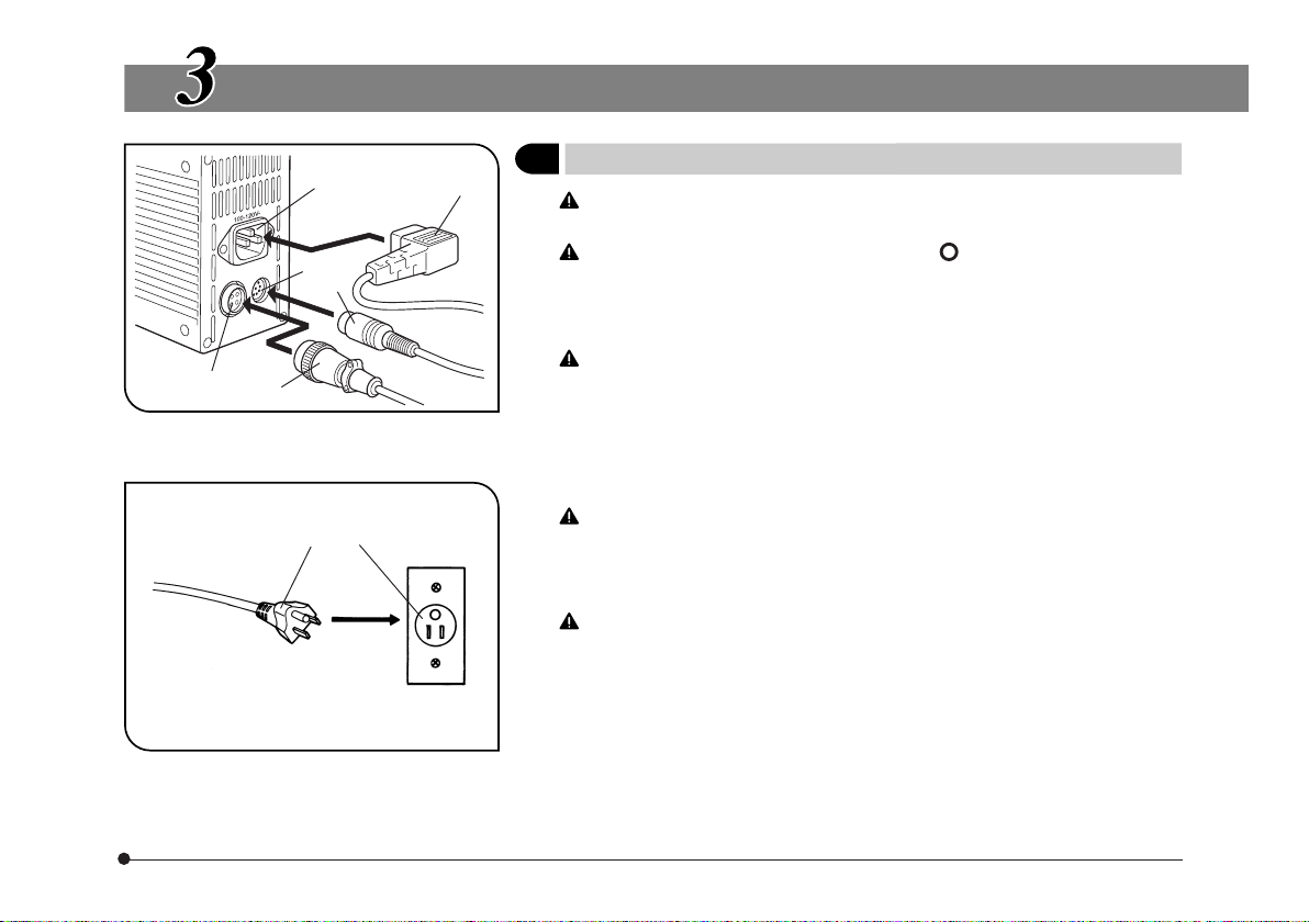
4. Always use the power cord provided by Olympus. If no power cord is provided, please select the proper power cord by
referring to the chapter “PROPER SELECTION OF THE POWER SUPPLY CORD” at the end of this instruction manual.
5. Always set the main switch on the power supply unit to “ ” (OFF) before connecting the power cord to the wall outlet.
6. This power supply is air-cooled so its surfaces become hot during operation. When installing it, leave spaces of more than
10cm around it. Also make sure to distribute cables away from the power supply.
7. To avoid potential shock hazard, make sure that the power cord is properly grounded.
8. Be sure to set the main switch to “ ” (OFF) and unplug the power cord before replacing the halogen lamp bulb.
9. The surfaces of the lamp housing will become extremely hot. When installing the lamp housing, be sure to allow ample free
spaces around and in particular above and below the lamp housing.

TH4
2
Safety Symbols
Symbol Meaning
Before use, carefully read the instruction manual. Improper use could result in personal injury to
the user and/or damage to the equipment.
Indicates that the main switch is ON.
Indicates that the main switch is OFF.
1Maintenance and Storage
1. Do not attempt to use organic solvents to clean the power supply unit. To clean it, use a lint-free, soft cloth slightly
moistened with a diluted neutral detergent.
2. Never attempt to disassemble any part of the power supply unit.
The following symbols are found on the power supply unit. Study the meaning of the symbols and always use the
equipment in the safest possible manner.
If the power supply unit is used in a manner not specified by this manual, the safety of the user may be imperiled. In
addition, the equipment may also be damaged. Always use the system as outlined in this instruction manual.
The following symbols are used to set off text in this instruction manual.
: Indicates that failure to follow the instructions in the warning could result in bodily harm to the
user and/or damage to equipment (including objects in the vicinity of the equipment).
# : Indicates that failure to follow the instructions could result in damage to equipment.
} : Indicates commentary (for ease of operation and maintenance).
2Caution

3
3Intended use
This instrument has been designed to be used to observe magnified images of specimens in routine and research
applications.
Do not use this instrument for any purpose other than its intended use.

TH4
4
NOMENCLATURE
Power Supply Unit TH4
Main switch
: ON
: OFF
Hand Switch TH4-HS (Optional)
Brightness control knob
Extension Cord U-RMT (Optional)
Compatible halogen lamp housing
Brightness control knob
POWER LED
REMOTE LED
Lamp ON-OFF switch
Extension cord (U-RMT)
Power supply unit (TH4)

5
COMPATIBLE HALOGEN LAMP HOUSING
Power Supply Unit
TH4
For halogen lamp housing
Halogen Lamp Housing
· U-LH100-3
· U-LH100L-3
· IX-ILL100LH
Any lamp housings other than described above
cannot be used with TH4.

TH4
6
ASSEMBLY
1Connecting the Cables and Cords (Fig. 1 & 2)
The cables and cords are vulnerable when bent or twisted. Never
subject them to excessive force.
Make sure that the main switch is set to “ ” (OFF) before connecting
cables and power cord. Otherwise equipment failure may result.
1. Insert the hand switch plug @ into the connector ².
2. Insert the lamp housing plug ³ into the connector |.
Always use the power cord provided by Olympus. If no power cord is
provided with the microscope, please select the proper power cord
by referring to chapter “PROPER SELECTION OF THE POWER SUP-
PLY CORD” at the end of this instruction manual.
3. Insert the power cord plug ƒ into the connector ….
4. Insert the power cord plug † into the wall power outlet ‡.
The power cord should be connected to a grounded, 3-conductor
power outlet. If the power outlet is not grounded properly, Olympus
can no longer warrant the electrical safety performance of the equip-
ment.
If a cable or the power cord comes in contact with the lamp socket or
the surroundings, the cable or cord may melt down, causing electric
shock hazards. Be sure to distribute the cables at enough distance
from the lamp housing and power supply unit.
Fig. 1
Fig. 2
³
²@
ƒ
…
|
‡†

7
Fig. 3
Fig. 4
OPERATION
1Voltage Indication (Fig. 3 & 4)
1. Ensure that the brightness control knob @ is set to MIN (lowest voltage)
then set the main switch ² to “ I” (ON). (The POWER LED ³ lights up.)
2. Turn the control knob @ toward MAX (highest voltage) to increase the
voltage intensity and brighten the illumination.
}The position marked indicates the position with which daylight suitable
for photography can be obtained when an LBD filter is engaged in the
light path.
Hand Switch Operation
}When the hand switch is connected (the REMOTE LED | lights), the
brightness control knob @ is defeated but the brightness control knob ƒ
of the hand switch is activated.
1. Press the lamp ON-OFF switch … and adjust the brightness with the con-
trol knob ƒ.
2. To turn the lamp OFF, press the lamp ON-OFF switch … again.
# When the REMOTE LED | is lit, the hand switch in standby mode and
consumes about 2.5 W of power.
When the equipment is not to be used for a long period of time, be sure to
set the main switch ² to “ ” (OFF).
|
²
@
³
…
ƒ

TH4
8
SPECIFICATIONS
Item Specification
Input rating
Output rating 0.9 to 12.6 V DC, 8.4A
Ventilation Natural
cooling
system
# Be sure to leave at least 10 cm (4 in.) of free spaces
between the walls or other solid objects.
Dimensions 75 mm (W) x 125 m (H) x 200 mm (D)
Weight Approx. 2.3 kg
Operating environment · Indoor use.
· Altitude: Max. 2000 meters
· Ambient temperature: 5° to 40°C (41° to 104° F)
· Maximum relative humidity: 80% for temperatures up to 31°C (88°F),
decreasing linearly through 70% at 34°C (93°F), 60% at 37°C
(99°F), to 50% relative humidity at 40°C (104°F).
· Supply voltage fluctuations: Not to exceed ±10% of the nominal
voltage.
· Pollution degree: 2 (in accordance with IEC60664-1)
·
Installation (overvoltage) category: II (in accordance with IEC60664-1)
· Transient overvoltage: 2500 V
· Temporary overvoltage:
TH4-100: 1320 V (up to 5 sec); 370 V (longer than 5 sec.)
TH4-200: 1440 V (up to 5 sec); 490 V (longer than 5 sec.)
TH4-100
TH4-200
100-120 V , 50/60 Hz, 1.8 A
200-240 V , 50/60 Hz, 0.9 A

9
CONTROL VIA THE REMOTE CONNECTOR
Recommended DIN 8-pin plug
· Connector type:TCP0500 Series
(mfd. by Hosiden Electronics Co., Ltd.)
DIN 8-pin connector
specifications
Pin No. Name
Analog input for light intensity control
Remote ON/OFF - H
Vcc (13.5 V) input
Analog input for light intensity control
using external VR - GND
Vcc (13.5 V) output
Detection of failed lamp
@
²
³
|
ƒ
…
†
# Be sure not to make a mis-
take with the connections.
# Input voltage rating: 4.75 to
5.25 V.
+5 V output

TH4
10
Fig. 5
1Controlling the Amount of Light According to
External Analog Voltage (Fig. 5)
}The amount of light can be varied between MIN and MAX by applying a
DC voltage input from 0 to 5 V.
1. Connect a DC power supply as shown in Fig. 5. Do not turn on the power
supply yet.
2. Set the main switch to “ I” (ON).
3. Apply the external analog voltage.
DC voltages from 0 to 5 V correspond to the light amount from MIN to
MAX.
# The external wiring should have a wire gauge of AWG28 (0.1 mm2) or
more.
# Do not apply voltage above 5 V DC. Doing so will cause the unit to
malfunction.
#Do not apply the analog voltage before setting the main switch to
“ I” (ON). Doing so will cause the unit to malfunction.
Inside the
power
supply unit
Control power
supply
(0-5 V DC)
1
4
5
3

11
Fig. 6
2Remote ON/OFF Operation (Fig. 6)
}The lamp can be turned off by shorting pins 4 and 2 of the DIN 8-pin
connector.
#The external wiring should have a wire gauge of AWG28 (0.1 mm2) or
more.
#The external contact should be fully capable of switching 10 mA on
and off.
#When the lamp is to be turned on/off with the open collector, connect
the emitter to pin 2.
Fig. 7
3Controlling the Amount of Light with External VR (Fig. 7)
Inside the power
supply unit }The amount of light can be controlled between MIN and MAX by connect-
ing an external VR.
1. Connect a VR as shown in Fig. 7.
2. Set the main switch to “ I” (ON).
3. The amount of light is minimized when the voltage at pin 1 is 0 V and
maximized when it is +5 V.
#The external wiring should have a wire gauge of AWG28 (0.1 mm2) or
more.
#Use an external VR of 10 0.1 W.
+5 V
ANALOG IN
6
1
4
2
4
Inside the power
supply unit
5.1 V
Vcc (13.5 V)
10
4.7

TH4
12
Fig. 8
4Detection of Failed Lamp
}Detects failed lamp and gives output alarm signal.
When lamp is normal: Open collector output is “ON” (i.e. there is a
short circuit between pins 4 and 7).
When lamp fails: Open collector output is “OFF” (i.e. there is
an open circuit between pins 4 and 7).
# The external wiring should have a wire gauge of AWG28 (0.1 mm2) or
more.
#External voltage connected to pin 4 should be negative and that
connected to pin 7 should be positive.
# External voltage should be limited to 40 V or less and current limited
to 5 mA or less.
Inside the power
supply unit
Detection of failed lamp
7
4

13
TROUBLESHOOTING GUIDE
Problem Cause Remedy Page
Under certain conditions, performance of the unit may be adversely affected by factors other than defects. If problems occur,
please review the following list and take remedial action as needed. If you cannot solve the problem after checking the entire list,
please contact your local Olympus representative for assistance.
1) Bulb intermittently lights and
goes out.
Bulb is nearly burned out. Replace bulb.
A cord plug is improperly connected. Check all connections.
2) POWER LED lights but bulb
does not light.
Bulb is nearly burned out. Replace bulb.
A cord plug is improperly connected. Check all connections.
Lamp ON-OFF switch on hand switch is
set to OFF.
Set it to ON.
3) Brightness cannot be in-
creased by turning brightness
control knob on power sup-
ply unit.
Brightness control knob on power supply
unit is disabled when hand switch is con-
nected.
Increase brightness with brightness con-
trol knob on hand switch.
**
6
**
6
7
7
** Please refer to the instruction manual of microscope for details.

TH4
14
Table 1 Certified Cord
A power supply cord should be certified by one of the agencies listed in Table 1 , or comprised of cordage marked with an
agency marking per Table 1 or marked per Table 2. The fittings are to be marked with at least one of agencies listed in
Table 1. In case you are unable to buy locally in your country the power supply cord which is approved by one of the
agencies mentioned in Table 1, please use replacements approved by any other equivalent and authorized agencies in
your country.
PROPER SELECTION OF THE POWER SUPPLY CORD
If no power supply cord is provided, please select the proper power supply cord for the equipment by referring to “ Specifications ” and
“ Certified Cord ” below:
CAUTION: In case you use a non-approved power supply cord for Olympus products, Olympus can no longer warrant the
electrical safety of the equipment.
Specifications
Voltage Rating
Current Rating
Temperature Rating
Length
Fittings Configuration
125V AC (for 100-120V AC area) or, 250V AC (for 220-240V AC area)
6A minimum
60°C minimum
3.05 m maximum
Grounding type attachment plug cap. Opposite terminates in molded-on IEC con-
figuration appliance coupling.

15
Country Agency Certification
Mark Country Agency Certification
Mark
Argentina
Australia
Austria
Belgium
Canada
Denmark
Finland
France
Germany
Ireland
IRAM
SAA
ÖVE
CEBEC
CSA
DEMKO
FEI
UTE
VDE
NSAI
Italy
Japan
Netherlands
Norway
Spain
Sweden
Switzerland
United
Kingdom
U.S.A.
ASTA
BSI
UL
IMQ
KEMA
NEMKO
AEE
SEMKO
SEV
JET, JQA, TÜV,
UL-APEX / MITI

TH4
16
Table 2 HAR Flexible Cord
APPROVAL ORGANIZATIONS AND CORDAGE HARMONIZATION MARKING METHODS
Approval Organization
Printed or Embossed Harmoniza-
tion Marking (May be located on
jacket or insulation of internal wir-
ing)
Alternative Marking Utilizing
Black-Red-Yellow Thread (Length
of color section in mm)
Black Red Yellow
Comite Electrotechnique Belge
(CEBEC)
Verband Deutscher Elektrotechniker
(VDE) e.V. Prüfstelle
Union Technique de l´Electricite´
(UTE)
Instituto Italiano del Marchio di
Qualita´ (IMQ)
British Approvals Service for Electric
Cables (BASEC)
N.V. KEMA
SEMKO AB Svenska Elektriska
Materielkontrollanstalter
CEBEC <HAR>
<VDE> <HAR>
USE <HAR>
IEMMEQU <HAR>
BASEC <HAR>
KEMA-KEUR <HAR>
SEMKO <HAR>
10 30 10
30 10 10
30 10 30
10 30 50
10 10 30
10 30 30
10 10 50

17
<ÖVE> <HAR>
<DEMKO> <HAR>
<NSAI> <HAR>
NEMKO <HAR>
<UNED> <HAR>
ELOT <HAR>
np <HAR>
SEV <HAR>
SETI <HAR>
30 10 50
30 10 30
30 30 50
10 10 70
30 10 70
30 30 70
10 10 90
10 30 90
10 30 90
Österreichischer Verband für
Elektrotechnik (ÖVE)
Danmarks Elektriske Materialkontroll
(DEMKO)
National Standards Authority of Ireland
(NSAI)
Norges Elektriske Materiellkontroll
(NEMKO)
Asociacion Electrotecnica Y
Electronica Espanola (AEE)
Hellenic Organization for
Standardization (ELOT)
Instituto Portages da Qualidade
(IPQ)
Schweizerischer Elektro
Technischer Verein (SEV)
Elektriska Inspektoratet
Underwriters Laboratories Inc. (UL) SV, SVT, SJ or SJT, 3 X 18AWG
Canadian Standards Association (CSA) SV, SVT, SJ or SJT, 3 X 18AWG
Table of contents
Other Olympus Power Supply manuals
Popular Power Supply manuals by other brands

EcoPower
EcoPower APT015W installation instructions

I-Tech
I-Tech IT-M3200 Programming guide

Tripp Lite
Tripp Lite HCRK-3 owner's manual

B+K precision
B+K precision 1680 instruction manual

B+K precision
B+K precision XLN3640 user manual

AutomationDirect
AutomationDirect RHINO PSS0524-100 installation instructions