Olympus U-RFL-T User manual

U-RFL-T
A X 7 7 1 3
INSTRUCTIONS
U-RX-T
This instruction manual is for the Olympus Power Supply for Mercury/Xenon Burner model U-RFL-T/
U-RX-T. To ensure the safety, obtain optimum performance and familiarize yourself fully with the use
of this module, we recommend that you study this manual thoroughly before operating it. After
reading, retain this instruction manual in an easily accessible place near the work desk for future
reference.
POWER SUPPLY FOR
MERCURY BURNER
POWER SUPPLY FOR
XENON BURNER
Optical Microscope Accessory

In accordance with European Directive on Waste Electrical and Electronic Equipment, this
symbol indicates that the product must not be disposed of as unsorted municipal waste, but
should be collected separately.
Refer to your local Olympus distributor in EU for return and/or collection systems available in
your country.
This product is applied with the requirements of standard IEC/EN61326-1 concerning
electromagnetic compatibility.
- Immunity Applied to industrial and basic environment requirements.
NOTE: This product has been tested and found to comply with the limits for a Class A digital device,
pursuant to Part 15 of the FCC Rules. These limits are designed to provide reasonable protection
against harmful interference when the product is operated in a commercial environment. This product
generates, uses, and can radiate radio frequency energy and, if not installed and used in accordance
with the instruction manual, may cause harmful interference to radio communications.
Operation of this product in a residential area is likely to cause harmful interference in which case the
user will be required to correct the interference at his own expense.
FCC WARNING: Changes or modifications not expressly approved by the party responsible for compliance
could void the user’s authority to operate the product.
For Korea only
이 기기는 업무용 환경에서 사용할 목적으로 적합성평가를 받은 기기로서 가정용
환경에서 사용하는 경우 전파간섭의 우려가 있습니다.

U-RFL-T/U-RX-T
CONTENTS
IMPORTANT
— Be sure to read this chapter for safe use of equipment. —
1-2
3
3-5
7
8
1 NOMENCLATURE
2 ASSEMBLY
2-1 Assembly Diagram 3
2-2 Detailed Assembly Procedures 4-5
3 PREPARATION
3-1 Turning the Burner ON 6
3-2 Centering the Burner 6
4 SPECIFICATIONS
5 TROUBLESHOOTING GUIDE
6
■■
■■
■PROPER SELECTION OF THE POWER SUPPLY CORD .................................................................. 9-10

1
The U-RFL-T power supply for mercury burner is designed exclusively for Olympus lamp housing for 100
W mercury burner, and the U-RX-T power supply for xenon burner is designed exclusively for Olympus
lamp housing for 75 W xenon burner.
IMPORTANT
1. Do not light the mercury or xenon burner while it is not mounted on the microscope. The UV rays in their light are harmful
to your eyes. Never look at the direct light output from the lamp housing.
2. Always use the lamp housing designated by Olympus for the power supply.
3. Make sure that the burner and connection cable are attached before setting the main switch of the power supply to “ I”
(ON).
4. Do not attempt to disassembly the power supply because it includes high-voltage parts inside.
5. Always use the power cord provided by Olympus. If no power cord is provided, please select the proper power cord by
referring to the section “PROPER SELECTION OF THE POWER SUPPLY CORD” at the end of this instruction manual. If the
proper power cord is not used, product safety and performance cannot be guaranteed.
6. Always ensure that the grounding terminal of the wall outlet is properly grounded/earthed. If the equipment is not grounded/
earthed, Olympus can no longer warrant the electrical safety performance of the equipment.
7. Replace the burner when the hour counter on the power supply indicates the end of burner service life. Using a burner
after its life has expired may result in the burner burst.
8. The power supply has ventilation openings on both sides. Install the power supply by leaving a space of more than 10
cm on each side, and do not let a metallic object enter the unit through the openings (to prevent electric shock or
malfunction).
SAFETY PRECAUTIONS
Safety Symbols
The following symbols are found on the power supply. Study the meaning of the symbols and always use the equipment
in the safest possible manner.
Symbol Explanation
Be careful against high voltage applied inside the unit.
Before use, carefully read the instruction manual. Improper handling could result in injury to
the user and/or damage to the equipment.
Indicates that the main switch is ON.
Indicates that the main switch is OFF.

2
U-RFL-T/U-RX-T
1Getting Ready
1. This manual pertains only to the handling of the power supply. For other information, please refer to the instruction
manuals for the lamp housing and microscope used in combination with the power supply so that you can understand
the comprehensive operating procedures of the system.
2. Do not use the unit where it is subjected to direct sunlight, high temperature and humidity, dust or vibrations. (For the
operating conditions, refer to chapter 4, “SPECIFICATIONS” on page 7.)
3. Turning the burner on/off frequently shortens its service life considerably. When you are going to interrupt observation for
a short period of time, it is recommended to leave the burner on and screen the light with the shutter, etc.
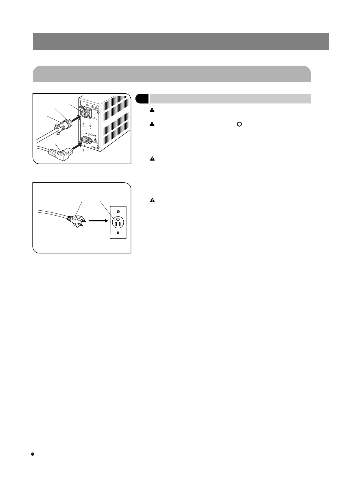
4. The power cord is also used to shut off the power supply in case of an emergency. Install the power supply so that the
power cord connector or the wall power outlet is easily accessible from the operator.
2Maintenance and Storage
1. If any part of the equipment gets dirty, with it with a clean cloth.
If the part is extremely dirty, do not attempt to use organic solvents to clean it; instead, use a soft, lint-free cloth slightly
moistened with a diluted neutral detergent.
2. When disposing of the power supply. Check the regulations and rules of your local government and be sure to observe
them.
If you cannot dispose of a used mercury burner yourself, please contact Olympus.
3Caution
If the power supply is used in a manner not specified by this manual, the safety of the user may be imperiled. In addition,
the equipment may also be damaged. Always use the equipment as outlined in this instruction manual.
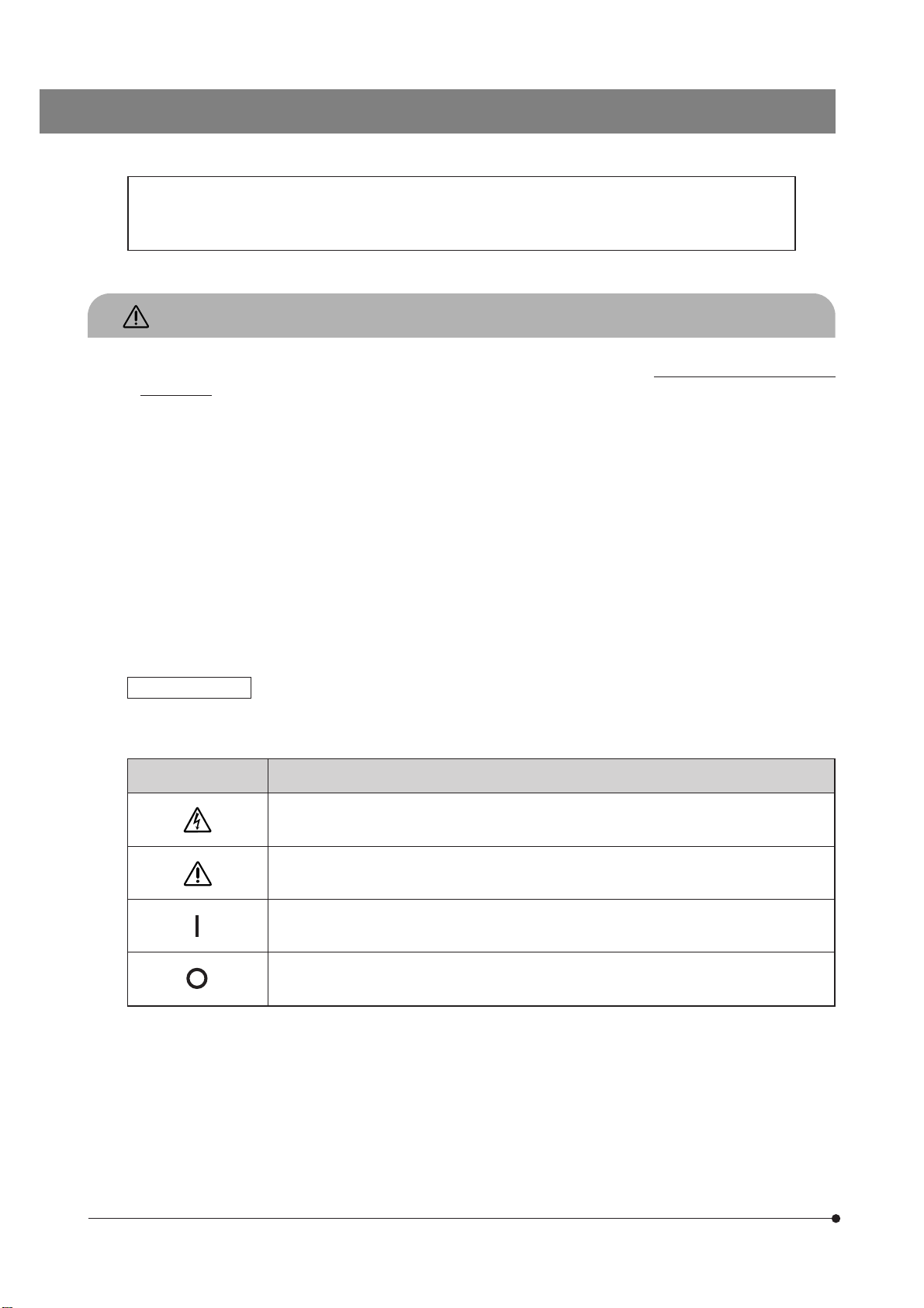
The following symbols are used to set off text in this instruction manual.
: Indicates that failure to follow the instructions in the warning could result in bodily harm to the
user and/or damage to equipment (including objects in the vicinity of the equipment).
# : Indicates that failure to follow the instructions could result in damage to equipment.
} : Indicates commentary (for ease of operation and maintenance).

3
1
NOMENCLATURE
}The following illustration shows the U-RFL-T, but the appearance of the U-RX-T is identical.
Hour counter
Reset button
Burner ON LED
Main switch
Lamp housing connector
Power cord connector
ASSEMBLY
2-1 Assembly Diagram
Applicable microscope
AX, BX, BX2, MX, MX2,
GX, IX or IV2 series
Power Supply for
Mercury Burner
U-RFL-T
Power Supply for
Xenon Burner
U-RX-T
Power cord
· Olympus Lamp Housing
for 100 W
Mercury Burner
· Mercury Burner
USH-1030L
· Olympus Lamp Housing
for 75 W
Xenon Burner
· Xenon Burner
UXL-75XB
(Counts up by 0.1
every 6 minutes.)
I: ON
: OFF

4
U-RFL-T/U-RX-T
The lamp housing cable and power cord are vulnerable to bend or
twist. Do not apply excessive force to them.
Be sure to set the main switch to “ ” (OFF) before connecting the
lamp housing cable and power cord.
1. Insert the cable @ from an applicable lamp housing into the lamp housing
connector ² by aligning the connectors, and secure using the clamping
ring ³ on the lamp housing connector.
Always use the power cord provided by Olympus. If no power cord
is provided, please select the proper power cord by referring to the
section “PROPER SELECTION OF THE POWER SUPPLY CORD” at
the end of this instruction manual.
2. Insert connector | of the power cord into connector ƒ of the power
supply firmly.
Always use the power cord supplied by Olympus and connect it to a
3-conductor wall outlet with a grounding terminal. If the grounding
terminal of the wall power outlet is not grounded/earthed, Olympus
can no longer warrant the electrical safety performance of the
equipment.
3. Insert the plug … of the power cord into the wall power outlet †.
Fig. 2
@
²
³
|
ƒ
2-2 Detailed Assembly Procedures
1Connecting the Cable and Power Cord (Figs. 1 & 2)
Fig. 1
…†

5
1. Push the reset button @ inside the reset button guard so that the hour
counter ² reads “0.0”.
Do not push the reset button @until the next time the burner is
replaced.
2. Figure “0.0” represents the hour of use. The reading counts up by 0.1
every 6 minutes.
3. When the life counter indicates the end of service life specified for each
burner, replace it for safety, even if the burner seems to be usable further.
Using a burner after its life has expired may result in the burner
burst.
}The burner light increases flickering when the end of its service life
approaches. In this case, it is recommended to replace it earlier depending
on the purpose of observation.
Fig. 3
@
²
2
Setting/Resetting the Hour Counter (Fig. 3)
Standard Burner Life
· Mercury burner USH-103OL: 300 hours*
· Xenon burner UXL-75XB: 200 hours**
**Average life under a lighting condition of 2-hour on/30-minute off
cycle. Turning the burner ON-OFF repeatedly in a shorter cycle
decreases the burner service life considerably.
** Average life under a lighting condition limiting every on period within
60 minutes. Turning the burner ON-OFF repeatedly in a shorter period
decreases the burner service life considerably.
}If you keep using the burner exceeding its life, the power supply unit may
detect the abnormality and the burner may blink.
In such a case, stop using the burner and replace the burner.

6
U-RFL-T/U-RX-T
Fig. 4
@
²
PREPARATION
3-1 Turning the Burner ON
1. Set the main switch @ of the power supply to “ I ” (ON).
2. The burner is ignited automatically by the auto ignition mechanism.
If the mercury burner is not ignited even though passing 30 seconds or
more after the main switch @ of the power supply unit is set to “ I ” (ON),
set the main switch @ to “ ” (OFF) once, and wait 10 seconds or more
and set the main switch @ to “ I ” (ON) again.
3. The lamp on LED ² lights up when the burner is ignited.
4. After ignition, the arc image of mercury burner stabilized in 5 to 10 minutes
and that of xenon burner stabilizes in 3 to 5 minutes.
The mercury burner cannot be re-ignited immediately after extinction.
After turning it off, wait for about 10 minutes, until the mercury vapor
inside it cools down and liquefies.
3-2 Centering the Burner
For centering of the burner, refer to the description on the burner centration in the instruction manual provided with the
microscope in use or an accessory module.
CAUTION

7
SPECIFICATIONS
Power Supply for Mercury Burner U-RFL-T
Item Specification
Ignition method Auto ignition
Hour counter Accumulated display of on time (0.1 countup per 6 minutes.)
Input rating 100-240 V AC , 50/60 Hz, 1.6 A (Power consumption 150 W)
Dimensions & weight 90(W) x 180(H) x 270(D) mm, approx. 3 kg
Applicable lamp housing Olympus lamp housing for 100 W mercury burner
Applicable mercury burner Ultrahigh-pressure mercury burner
USH-103OL*(Olympus)
*The USH-102D (Ushio) and HBO103W/2 (Osram) are also applicable.
However, performance cannot be guaranteed when the HBO103W/2
is used.
Power Supply for Xenon Burner U-RX-T
Item Specification
Ignition method Auto ignition
Hour counter Accumulated display of on time (0.1 countup per 6 minutes.)
Input rating 100-240 V AC , 50/60 Hz, 1.6 A (Power consumption 150 W)
Dimensions & weight 90(W) x 180(H) x 270(D) mm, approx. 3 kg
Applicable lamp housing Olympus lamp housing for 75 W xenon burner
Applicable mercury burner 75 W xenon burner
UXL-75XB (Ushio)
Operating Environment
· Indoor use.
· Altitude: Max. 2000 meters.
· Ambient temperature: 5° to 40°C (41° to 104° F).
· Relative humidity: 80% for temperatures up to 31°C (88°F), decreasing linearly through 70% at 34°C (93°F),
60% at 37°C (99°F) to 50% relative humidity at 40°C (104°F).
· Supply voltage fluctuations: ±10%.
· Pollution degree: 2 (in accordance with IEC60664).
· Installation (overvoltage) category: II (in accordance with IEC60664)

8
U-RFL-T/U-RX-T
TROUBLESHOOTING GUIDE
Under certain conditions, performance of the unit may be adversely affected by factors other than defects. If problems occur,
please review the following list and take remedial action as needed.
Problem Cause Remedy Page
a) Field of view is obscured, or field of
view is not evenly illuminated.
The objective is engaged improperly in
the light path.
Engaging the objective in the click
position of the revolving nosepiece. –
The revolving nosepiece is installed
improperly.
Push the revolving nosepiece all the
way in. –
The field iris diaphragm is stopped down
too much.
Open the field iris diaphragm. –
The burner is not centered. Adjust the centering. 6
b) The lamp does not light even when
the main switch is set to “ I” (ON).
Connectors are inserted improperly. Connect them firmly. 4
The interlock mechanism of the lamp
housing is activated.
Tighten the lamp socket clamping
screw firmly. –
The temperature switch is activated by
heating.
Remove any obstacle from around the
ventilation openings, and wait until the
unit cools down before setting the
main switch to “ I” (ON) again.
–
The auto ignition mechanism is
malfunctioning.
Set the main switch @ to “ ” (OFF)
once, and wait 10 seconds or more and
set the main switch @ to “ I” (ON) again.
6
No burner is installed. Install a burner.
#Never turn the unit ON without in-
stalling a burner. It is extremely
hazardous and may cause a fail-
ure.
–
c) The burner light flickers or is dark. Enough time has not elapsed since the
burner ignition.
Wait until the arc stabilizes. 6
The burner service life has expired. If the hour counter indicates time
above the service life, replace the
burner.
5
d) The burner is extinguished in the
middle of observation.
The temperature switch is activated
because the ventilation openings of the
lamp housing are blocked.
Remove any obstacle from around the
ventilation openings, and wait until the
unit cools down before setting the
main switch to “ I” (ON) again.
–

9
PROPER SELECTION OF THE POWER SUPPLY CORD
If no power supply cord is provided, please select the proper power supply cord for the equipment by referring to “ Specifications ” and
“ Certified Cord ” below:
CAUTION: In case you use a non-approved power supply cord for Olympus products, Olympus can no longer warrant the
electrical safety of the equipment.
Specifications
Voltage Rating
Current Rating
Temperature Rating
Length
Fittings Configuration
125V AC (for 100-120V AC area) or, 250V AC (for 220-240V AC area)
6A minimum
60°C minimum
3.05 m maximum
Grounding type attachment plug cap. Opposite terminates in molded-on IEC con-
figuration appliance coupling.
Table 1 Certified Cord
A power supply cord should be certified by one of the agencies listed in Table 1 , or comprised of cordage marked with an
agency marking per Table 1 or marked per Table 2. The fittings are to be marked with at least one of agencies listed in
Table 1. In case you are unable to buy locally in your country the power supply cord which is approved by one of the
agencies mentioned in Table 1, please use replacements approved by any other equivalent and authorized agencies in
your country.
Country Agency Certification
Mark Country Agency Certification
Mark
Argentina
Australia
Austria
Belgium
Canada
Denmark
Finland
France
Germany
Ireland
IRAM
SAA
ÖVE
CEBEC
CSA
DEMKO
FEI
UTE
VDE
NSAI
Italy
Japan
Netherlands
Norway
Spain
Sweden
Switzerland
United
Kingdom
U.S.A.
IMQ
KEMA
NEMKO
AEE
SEMKO
SEV
ASTA
BSI
UL
JET, JQA, TÜV,
UL-APEX / MITI

10
U-RFL-T/U-RX-T
Table 2 HAR Flexible Cord
APPROVAL ORGANIZATIONS AND CORDAGE HARMONIZATION MARKING METHODS
Approval Organization
Printed or Embossed Harmoniza-
tion Marking (May be located on
jacket or insulation of internal wir-
ing)
Alternative Marking Utilizing
Black-Red-Yellow Thread (Length
of color section in mm)
Black Red Yellow
Comite Electrotechnique Belge
(CEBEC)
Verband Deutscher Elektrotechniker
(VDE) e.V. Prüfstelle
Union Technique de l´Electricite´
(UTE)
Instituto Italiano del Marchio di
Qualita´ (IMQ)
British Approvals Service for Electric
Cables (BASEC)
N.V. KEMA
SEMKO AB Svenska Elektriska
Materielkontrollanstalter
Österreichischer Verband für
Elektrotechnik (ÖVE)
Danmarks Elektriske Materialkontroll
(DEMKO)
National Standards Authority of Ireland
(NSAI)
Norges Elektriske Materiellkontroll
(NEMKO)
Asociacion Electrotecnica Y
Electronica Espanola (AEE)
Hellenic Organization for
Standardization (ELOT)
Instituto Portages da Qualidade
(IPQ)
Schweizerischer Elektro
Technischer Verein (SEV)
Elektriska Inspektoratet
CEBEC <HAR>
<VDE> <HAR>
USE <HAR>
IEMMEQU <HAR>
BASEC <HAR>
KEMA-KEUR <HAR>
SEMKO <HAR>
<ÖVE> <HAR>
<DEMKO> <HAR>
<NSAI> <HAR>
NEMKO <HAR>
<UNED> <HAR>
ELOT <HAR>
np <HAR>
SEV <HAR>
SETI <HAR>
10 30 10
30 10 10
30 10 30
10 30 50
10 10 30
10 30 30
10 10 50
30 10 50
30 10 30
30 30 50
10 10 70
30 10 70
30 30 70
10 10 90
10 30 90
10 30 90
Underwriters Laboratories Inc. (UL) SV, SVT, SJ or SJT, 3 X 18AWG
Canadian Standards Association (CSA) SV, SVT, SJ or SJT, 3 X 18AWG

MEMO


AX7713 10
Distributed by
Manufactured by
Shinjuku Monolith, 2-3-1 Nishi-Shinjuku, Shinjuku-ku, Tokyo 163-0914, Japan
www.olympus-global.com
Other manuals for U-RFL-T
1
This manual suits for next models
1
Table of contents
Other Olympus Power Supply manuals