manuals.online logo
Brands
  1. Home
  2. •
  3. Brands
  4. •
  5. OM POWER
  6. •
  7. Amplifier
  8. •
  9. OM POWER OM2000+ User manual

OM POWER OM2000+ User manual

Exhibit 11 Page 1 of 12
Exhibit 11: Tuning Procedure and
Parts List
External Radio Frequency
Power Amplifier OM2000+
Model 2000+
Array Solutions
2611 North Beltline Rd
Suite 109
Sunnyvale, Texas 75182
USA
Tel: 214 954 7140
fax: 214 954 7142
E-mail: info@arraysolutions.com
Exhibit 11 Page 2 of 12
1.2. Tuning of the Power Amplifier
The OM2000+ power amplifier is operated in class AB. Thus it’s possible to obtain a maximum output
power at excellent linearity. For this purpose the amplifier has to be tuned carefully.
CAUTION
The operation of a mistuned PA will cause malfunctions, the increase of grid current and problems
with TVI/BCI.
CAUTION
If the input power is higher than 10W and the power amplifier is NOT correctly tuned, the safety
devices will switch it to STBY. After switching the amplifier to STBY, you need to switch it back to
the OPER mode by pressing RESET button shortly.
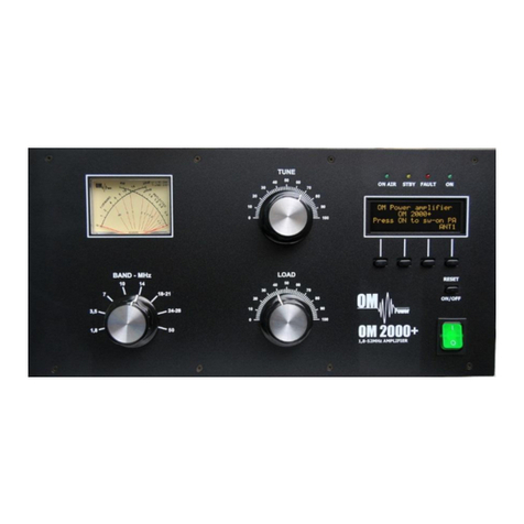
A tuning table is delivered with the power amplifier. For coarse tuning select a band with BAND switch
and choose the setting of “TUNE” and “LOAD” capacitors according to the table.
Band (MHz)
Tune
Load
Input PWR (W)
Output PWR (W)
1.845
70
45
75
1500
3.630
69
51
72
1500
7.050
50
90
71
1500
10.125
72
28
72
1500
14.175
69
40
70
1500
18.150
81
48
69
1500
21.230
47
67
65
1500
24.940
61
64
59
1500
28.450
33
76
52
1500
50.200
22
90
64
1500
NOTE
Delivered tuning table was made for 50 Ohm loading of PA (dummy load). Each amplifier should have
different values depending on used frequency and used type of antenna. Make your own table valid
for your real conditions.
There are two ways how to do fine tuning. The first method uses a gradual increase in the input power
when tuning the PA (as most operators accustomed). In every case we recommend adjust the display
for both of methods so it shows two parameters important for fine tuning - TUNE and Is graph (> l <).
Exhibit 11 Page 3 of 12
Press OPER to enter operation mode. Apply low input power and press PTT. Be sure you selected right
BAND, TUNE and LOAD knob positions. If you made some mistake, fault message appears:
Safety circuit stopped transmitting, fault LED
is ON (Fault code 4 is saving to the memory).
Release PTT, set proper positions of BAND,
TUNE and LOAD according to the table and
press PTT again.
Another mistake can occur, if you have antenna connected to the wrong output. In such a case „SWR
is too high“ error message appears. Change antenna output using S4 button.
This is not an optimal result, TUNE indicator
must go between both arrows. Use TUNE
knob to get maximum output power and
LOAD knob to get indicator between
arrows.
Another example of not optimal result, TUNE
indicator must go between both arrows. Use
TUNE knob to get maximum output power
and LOAD knob to get indicator between
arrows (in arrows direction).
This is a good result of tuning.
Now increase input power slowly and watch the display.
Type of supported TCVR and working
frequency are visible on the display.
AUTO LED is ON.
Type of supported TCVR and working
frequency are visible on the display.
AUTO LED is ON.
Type of supported TCVR and working
frequency are visible on the display.
AUTO LED is ON.
Type of supported TCVR and working
frequency are visible on the display.
AUTO LED is ON.
Exhibit 11 Page 4 of 12
Two of important information is visible –
screen current increased, but still is within
the allowed limits. Turn LOAD knob slightly
in arrows direction to get TUNE indicator
between arrows.
Display indicates correct tuning of the Power
amplifier.
Remember
Always use TUNE knob to get maximum output power. Use LOAD knob to get TUNE indicator on the
display to the middle position between both arrows. Simultaneously check if Is graph indicator stays
within the boundaries. Repeat both steps more times.
Proper operation mode of FU-728F requires the plate voltage to be close to 3 kV. If anode voltage
without RF power is much lower, watch the heating voltage, too. Normally, heating voltage must be in
boundaries from 8.5 to 9 V without RF signal (DSP3). Heating voltage level is a reliable indicator of
correct AC selector adjustment. If you see heating voltage lower than 8.5V without RF signal, change
primary AC voltage selector one step down (if possible). Conversely, if the voltage is higher than 9V,
try to move AC selector one step up (for example from 220 to 230 VAC). Check heating voltage under
full load (full output power), also. If the heating voltage without RF signal is OK but under full load
drops more than 1.5 V, this relates to the „soft“ AC network and is solvable only by „changing“ the AC
network...
Without RF power the plate voltage is OK.
Without RF power the plate voltage is 2.85 kV.
Check the heating voltage, too. If it is below
8.5 V, this indicates the need to change AC
selector position one step down (for example
from 230 to 220 VAC).
Type of supported TCVR and working
frequency are visible on the display.
AUTO LED is ON.
Type of supported TCVR and working
frequency are visible on the display.
AUTO LED is ON.
Type of supported TCVR and working
frequency are visible on the display.
AUTO LED is ON.
Type of supported TCVR and working
frequency are visible on the display.
AUTO LED is ON.
Exhibit 11 Page 5 of 12
To start the second method of fine tuning, press S2 (TUNE) button in OPER mode.
PA is in the operation mode. After TUNE
button (S2) was pressed, it changes its
function. Now STOP is blinking.
Do not press STOP button yet!
Apply input power according tune table (or lower) for selected band and press PTT. Use TUNE knob to
get maximum output power. Use LOAD knob to get Is graph indicator within the boundaries.
Display shows properly tuned PA.
TUNE indicator is in the middle, Screen
current is higher, but still inside the limits.
After proper fine tuning release PTT and press STOP button. PA is now prepared for operation.
View on the properly tuned PA. Analog
wattmeter shows forwarded and reflected
power.
After this procedure the amplifier is tuned correctly and ready to give 1500 W output power in all
operation modes. At optimal tuning and full output power a positive max. 50mA current goes through
the second grid.
CAUTION
If the amplifier demonstrate any malfunctions during tuning or it does not behave in accordance
witch the description, interrupt the tuning procedure immediately and check the amplifier! Be sure
not to do any mistakes in choosing bands or TUNE/LOAD values! Be sure that VSWR is not higher
than 2:1 and input power is LOW!
After excluding possible human mistakes you will be able to work for long time with this amplifier!
Type of supported TCVR and working
frequency are visible on the display.
AUTO LED is ON.
Type of supported TCVR and working
frequency are visible on the display.
AUTO LED is ON.
Type of supported TCVR and working
frequency are visible on the display.
AUTO LED is ON.
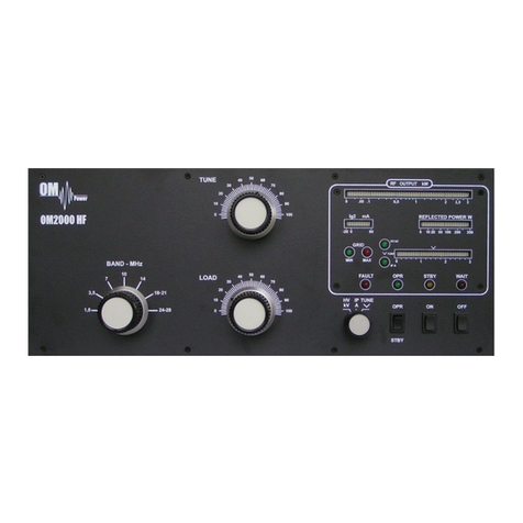
Exhibit 11 Page 6 of 12
OM2000+ PARTS LIST
Item No.
Description
Qty.
1
Analog meter FWD / REF
70x70mm
1
2
Band switch 8x3
8x3 position
1
3
Blower
24V 5,28W
PE92252V1-000U
1
4
Blower ebm-papst
230V 30W
G2E085-AA01-01
1
5
Bridge
KBU8J
8A 600V
4
6
Bridge
B380C
0,8A 900V
1
7
Bridge
DB157S
1,5A 1000V
2
8
Capacitor ceramic
4n7 6kV
15,24mm
4
9
Cap ceramic disc
2n2 10kV
Φ 40mm
1
10
Cap ceramic disc
330 3,5kV
Φ 30mm
1
11
Cap ceramic disc
1n 12kV
Φ 30mm
1
12
Cap ceramic disc
470 16kV
Φ 25mm
1
13
Capacitor ceramic
1µF 50V
1206
4
14
Capacitor ceramic
100pF 50V
1206
12
15
Capacitor ceramic
100n 50V
0805
5
16
Capacitor ceramic
100n 50V
1206
66
17
Capacitor ceramic
100n 500V
5mm
5
18
Capacitor ceramic
100nF/1kV
10mm
6
19
Capacitor ceramic
10n 50V
1206
19
20
Capacitor ceramic
10n / 1kV
5mm
1
21
Capacitor ceramic
10nF 500V
5mm
10
22
Capacitor ceramic
10nF / 1kV
10mm
9
23
Capacitor ceramic
10pF 500V
1210
2
24
Capacitor ceramic
15pF 50V
1206
2
25
Capacitor ceramic
1n /50V
0805
4
26
Capacitor ceramic
1n 500V
5mm
2
27
Capacitor ceramic
1nF 50V
1206
9
Exhibit 11 Page 7 of 12
28
Capacitor ceramic
22 50V
1206
1
29
Capacitor ceramic
2n2 500V
7,62mm
1
30
Capacitor ceramic
2nF 500V
7,62mm
1
31
Capacitor ceramic
3,3pF 500V
5mm
1
32
Capacitor ceramic
3n3 500v
5mm
1
33
Capacitor ceramic
4.7pF 500V
1210
2
34
Capacitor ceramic
47n 250V
15,24mm
2
35
Capacitor ceramic
47pF 500V
1210
1
36
Capacitor ceramic
59pF 500V
1210
1
37
Capacitor ceramic
76pF 500V
1210
1
38
Capacitor electrolytic
330µF 450V
10,16 SNAP-IN
8
39
Capacitor electrolytic
47µF 250V
7,62_ELKO
2
40
Capacitor electrolytic
47µF 450V
7,62_ELKO
2
41
Capacitor electrolytic
1000µF / 35V
1411_ELKO
1
42
Capacitor electrolytic
10µF / 16V
SMD 1210
6
43
Capacitor electrolytic
22µF / 16V
1206
1
44
Capacitor electrolytic
10M /16V
1206
1
45
Capacitor electrolytic
330µF / 6V
SMD_R7X7_ELKO
1
46
Capacitor electrolytic
47µF/10V
1206
1
47
Coil
Stopper coil
1
48
Coil
anode choke on PTFE
1
49
Coil
choke 100uH 2,5A
1
50
Coil
Air coil
1
51
Coil
L coil on ceramics
2
52
Coil
choke coil on PTFE
2
53
Connector
PV02-5,08-H-P
5,08
1
54
Connector
PV03-5,08-H-P
5,08
1
55
Connector
PV06-5,08-V-P
5,08
1
56
Connector
PV04-5,08-H-P
5,08
2
57
Connector
LPH10
10-S
1
58
Connector
LPH06
6-S
2
Exhibit 11 Page 8 of 12
59
Connector
LPH16S
16-S
3
60
Connector
FASTIN
1X01
1
61
Connector
FASTON
MKDSN1,5/2-5,08
2
62
Connector
LPH20
LPH20SMD
1
63
Connector
LPH20RA
LPH20RA
1
64
Connector
LPH16RA
LPH16RA
4
65
Connector
LPH10RA
LPH10RA
2
66
Connector
LPH06RA
LPH06RA
3
67
Connector
WWS 10G
1X06
1
68
Connector
NSL 25-2W
PSS254/2W
3
69
Connector
NSL 25-4W
PSS254/4W
2
70
Connector
NSL 25-4 G
PSS254/2G
3
71
Connector
NSL 25-2G
PSS254/2G
9
72
Connector
NSL 25-3G
PSS254/2G
1
73
Connector cinch
CHINCH CC133B
1
74
Connector cinch
CHINCH CC133B
1
75
Diode
1N5408
DO27
1
76
Diode
1N4148
DO35
1
77
Diode Schottky
TMMBAT46
MINIMELF_DIODE
4
78
Diode Schottky
BAT41
MINIMELF
2
79
Diode Si
1N4007 1A 1000V
DO41
3
80
Diode SMD
TS4148
1206-D
3
81
Diode SMD
SM4007
MELF
1
82
Diode SMD
LL4148
MINIMELF_DIODE
13
83
Diode SMD
BAR43C
SOT23/3
3
84
Diode SMD
SKL34
MINIMELF_DIODE
2
85
Diode Zenner
18v
DO41
1
86
Diode Zenner
1N5349 12V 5W
DO201AD
2
87
Diode Zenner
1N5363 30V 5W
DO41
1
88
Diode Zenner
1N5384 160V 5W
DO201AD
2
89
Diode Zenner
BZV85C 20V
DO41
1
Exhibit 11 Page 9 of 12
90
Diode Zenner
BZV85C 30V
DO41
1
91
Diode Zenner
BZV85C 4V7
DO41
1
92
Diode Zenner
BZV85C 5V1
MINIMELF_DIODE
1
93
Diode Zenner
BZV85C 6V8
MINIMELF_DIODE
19
94
Diode Zenner
SK54
SMB
1
95
Diode Zenner
ZD 5V1
SOD80
1
96
Diode Zenner
ZD 8V
SOD80
1
97
EMI filter
BLM31
1206
12
98
EMI filter
BLM21PG221
0805
15
99
EMI filter
BLM31PG221
1206
6
100
Filter EPCOS
250V20A
B84771A0020A000
1
101
Fuse
F4A
5 x 20mm
1
102
Fuse
250mA
5 x 20mm
1
103
Fuse
T2A
5 x 20mm
4
104
Fuse
1A
5 x 20mm
1
105
Fuse
T500mA
5 x 20mm
2
106
Fuse
T3,15
5 x 20mm
1
107
Fuse
T2A
5 x 20mm
1
108
Fuse
10A
5 x 20mm
1
109
Fuse 6,3x32mm Slow
T 16A Fuse Slow
6,3x32mm
2
110
Choke
1mH
0207
1
111
Choke
100uH
0207
6
112
IC
TLC272ACP
DIL8
1
113
IC SMD
74AHC74
SO14
1
114
IC SMD
MAX232CSE
SO16_SOT109-1
1
115
IC SMD
TLC272
SO8_SOT96-1
1
116
IC SMD
ICL7660ACPA
SO8
1
117
IC SMD
MCP4017T-5
SC70-6
1
118
IC SMD
LM358AD
SO8_SOT96-1
3
119
IC SMD
TA78L08F
SOT89
1
120
IC SMD
TA78L05F
SOT89
1
Exhibit 11 Page 10 of 12
121
IC SMD
LM4040-2.5
SOT23/3
1
122
LED_3mm
LED_3mm
LED_3MM
4
123
LED_yellow_5mm
Backlight
LED_5mm
1
124
OLED Display
EA-W204
EA-W204 DISP
1
125
Photo-coupler
PC817
DIL4
1
126
Power switch
250V 10A
Marquardt
1
127
Processor
PIC18F8722
TQFP80
1
128
Quartz crystal
20MHz
HC49_SMD
1
129
Relay
G2-RL
Omron_G2RL-1-E
2
130
Relay
LYCA024
Finder_34.51
2
131
Relay
SY-12W
RELAIS-SY
1
132
Relay
G6K
Omron_G6K-2F
3
133
Relay
FTR-B3
FTR-B3GA012Z
1
134
Relay
FTR K1
G2RL-1-E
3
135
Relay vacuum
RH4894
Siemens
1
136
Resistor Adj.
100k
PT10LV
2
137
Resistor
10
5X12R15,24
2
138
Resistor
10 / 15w
9X38R50,8
1
139
Resistor
100
1206
25
140
Resistor
100
0207_MET
6
141
Resistor
100k
R 2W
1
142
Resistor
100k
4X12R15,24
1
143
Resistor
100K
1206
13
144
Resistor
10K
0207_MET
6
145
Resistor
10k
1206
46
146
Resistor
10k
5X12R15,24
1
147
Resistor
120k
1206
1
148
Resistor
12k
1206
1
149
Resistor
150k
5X12R15,24
9
150
Resistor
150k
0207
1
151
Resistor
160k
1206
1
Exhibit 11 Page 11 of 12
152
Resistor
180k
1206
1
153
Resistor
18k / 10W
0207
1
154
Resistor
1k
11X50R55,88
1
155
Resistor
1k
0207_MET
5
156
Resistor
1k
4X12R15,24
1
157
Resistor
1k
1206
24
158
Resistor
1k2
1206
1
159
Resistor
1k3
1206
1
160
Resistor
1M
R 2W
1
161
Resistor
1M
4X12R15,24
3
162
Resistor
20K
TRIMMER_23B
1
163
Resistor
22
1206
1
164
Resistor
22
10X46R50,8
1
165
Resistor
220
4X12R15,24
1
166
Resistor
220
1206
1
167
Resistor
220/2w
0207
1
168
Resistor
2k2 / 3w
4X12R15,24
1
169
Resistor
330k
0207_MET
2
170
Resistor
33k
0207
2
171
Resistor
3k9
1206
1
172
Resistor
3R3 /15w
9X50R55,88
1
173
Resistor
4k7
1206
23
174
Resistor
4R7 / 15w
9X50R55,88
1
175
Resistor
5.6k 2W
4X12R15,24
1
176
Resistor
50Ohm 250W
1
177
Resistor
51k
1206
1
178
Resistor
560
4X12R15,24
1
179
Resistor
5K
PT10LH
1
180
Resistor
68/2w
R 2W
1
181
Resistor
68k
0207_MET
2
182
Resistor
82/2w
R 2W
1
Exhibit 11 Page 12 of 12
183
Resistor
91k
1206
1
184
Resistor
M15
1206
1
185
Resistor
150
2512
6
186
Resistor
47k
1206
4
187
Resistor
2k2
1206
4
188
Resistor metal oxide
2 x 330/7W
1
189
Resistor metal oxide
1M 2W
3
190
Variable capacitor
70 + 250pF
1
191
Variable capacitor
400 + 400pF
1
192
Suppressor
600V
1
193
Switch
TASTER_18,5MM
5
194
Switching regulator
TSR1-2450
TRACO-TSR1-24
1
195
Switching regulator
47154
12V 5W
1
196
Thermistor disk
32A 1Ohm
1
197
Transformer
220/230/240V 2410W
1
198
Transil
BZW 06-12B
DO41
4
199
Transil
BZW06 10B
DO41
1
200
Transistor
2N3904
TO92
1
201
Transistor
IRFPG50PBF
TO247
2
202
Transistor
BC846B
SOT23/3
11
203
Transistor
BCX55-16
SOT89
17
204
Transistor
BCX53
SOT89
3
205
Transistor
BU806
TO220
1
206
Transistor
FZT955
SOT223
1
207
TUBE
FU728f
1

Other manuals for OM2000+

4

Other OM POWER Amplifier manuals

OM POWER OM2500 HF User manual

OM POWER

OM POWER OM2500 HF User manual

OM POWER OM2002+ User manual

OM POWER

OM POWER OM2002+ User manual

OM POWER OM2501A User manual

OM POWER

OM POWER OM2501A User manual

OM POWER OM2000A+ User manual

OM POWER

OM POWER OM2000A+ User manual

OM POWER OM2500 A User manual

OM POWER

OM POWER OM2500 A User manual

OM POWER OM1500 User manual

OM POWER

OM POWER OM1500 User manual

OM POWER OM2200HF User manual

OM POWER

OM POWER OM2200HF User manual

OM POWER OM2000+ User manual

OM POWER

OM POWER OM2000+ User manual

OM POWER OM2000A+ User manual

OM POWER

OM POWER OM2000A+ User manual

OM POWER OM2000+ User manual

OM POWER

OM POWER OM2000+ User manual

OM POWER OM2500 A-F User manual

OM POWER

OM POWER OM2500 A-F User manual

OM POWER OM4001F User manual

OM POWER

OM POWER OM4001F User manual

OM POWER OM2500 HF User manual

OM POWER

OM POWER OM2500 HF User manual

OM POWER OM2000A+ User manual

OM POWER

OM POWER OM2000A+ User manual

OM POWER OM2000+ User manual

OM POWER

OM POWER OM2000+ User manual

OM POWER OM2200A User manual

OM POWER

OM POWER OM2200A User manual

OM POWER OM1002+ User manual

OM POWER

OM POWER OM1002+ User manual

OM POWER OM4000 HF User manual

OM POWER

OM POWER OM4000 HF User manual

OM POWER OM3500A User manual

OM POWER

OM POWER OM3500A User manual

OM POWER OM4001A User manual

OM POWER

OM POWER OM4001A User manual

OM POWER OM4000HF User manual

OM POWER

OM POWER OM4000HF User manual

OM POWER OM2501HF User manual

OM POWER

OM POWER OM2501HF User manual

OM POWER OM2000+ User manual

OM POWER

OM POWER OM2000+ User manual

OM POWER OM1002 User manual

OM POWER

OM POWER OM1002 User manual

Popular Amplifier manuals by other brands

Phaedrus Philter user manual

Phaedrus

Phaedrus Philter user manual

Art TubeFire 8 user guide

Art

Art TubeFire 8 user guide

Glasshouse 300BSE Series manual

Glasshouse

Glasshouse 300BSE Series manual

Plantronics CA10 user guide

Plantronics

Plantronics CA10 user guide

Luxman L-550AX owner's manual

Luxman

Luxman L-550AX owner's manual

Rockford Fosgate T400X2ad Operation manual

Rockford Fosgate

Rockford Fosgate T400X2ad Operation manual

Sansui QS-100 Operating instructions & service manual

Sansui

Sansui QS-100 Operating instructions & service manual

Roland CUBE-100 BASS instructions

Roland

Roland CUBE-100 BASS instructions

ASR emitter user manual

ASR

ASR emitter user manual

FONESTAR FS-1240E instruction manual

FONESTAR

FONESTAR FS-1240E instruction manual

ifi micro iTubo2 quick start guide

ifi

ifi micro iTubo2 quick start guide

QSC ISA 280 user manual

QSC

QSC ISA 280 user manual

DaytonAudio WF40A quick start guide

DaytonAudio

DaytonAudio WF40A quick start guide

Hy-Gain 422 Installation & operation instructions

Hy-Gain

Hy-Gain 422 Installation & operation instructions

Taga TA-25Mini instruction manual

Taga

Taga TA-25Mini instruction manual

WJG HOLLYWOOD MXV-1200 Reference manual

WJG

WJG HOLLYWOOD MXV-1200 Reference manual

Pioneer 422070 220V owner's manual

Pioneer

Pioneer 422070 220V owner's manual

VocoPro DA-4080FX owner's manual

VocoPro

VocoPro DA-4080FX owner's manual

manuals.online logo
manuals.online logoBrands
  • About & Mission
  • Contact us
  • Privacy Policy
  • Terms and Conditions

Copyright 2025 Manuals.Online. All Rights Reserved.