5
1.2.2. Protection Circuits
There are several protection circuits used in the amplifier. They are activated when one
or more parameters exceed defined values or some unwanted condition occurs.
•VSWR too high
•Anode current too high
•Anode voltage error
•Screen current too high
•Screen voltage error
•Grid current too high
•Grid voltage error
•Heating voltage error
•Mistuning of PA
•Temperature too high
•Soft start for fuse protection
•“switch-on blocking “ at opened amplifier
1.2.3. Features
The manufacturer implemented some of the company’s newest development results with
most wanted operating and safety features into this new model:
•High level of protection
•Memory for faults and warnings, easy maintenance
•Automatic set-up anode current (BIAS) – no need to adjust manually after
changing the tube
•Three programmable working modes of the centrifugal blower ( turbine ) + axial blower
•Full QSK with silent relay
•Many operational parameters to display
•Easy transport due to detachable HV transformer
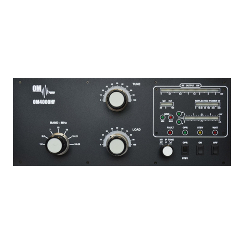
•The smallest and lightest 4000 W Power Amplifier on the market
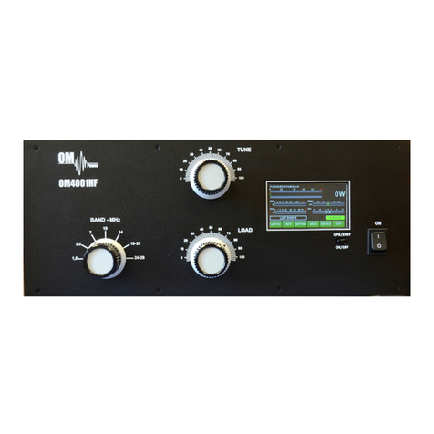
1.2.4. The Advantages of OM40001A
•Full compatibility with: ICOM, ELECRAFT, KENWOOD, TEN-TEC ORION, YAESU, Icom
transceive protocol using by MicroHAM devices ( CI-V output ), FLEX Radios and
Anan.
•RF sensitive Band and Frequency switching, for use with radios which do not
have CAT. We recommend using CAT and BAND DATA information
due to the much faster band changing whenever possible.
•Automatic switching between bands. Automatic tuning within the band according to segments.
•Automatic switching of Band Pass Filter – BAND DATA output compatible with YAESU radios
(BCD code).
•Automatic switching of Antenna switches. The maximum number of antennas is 10, controlled
by BCD output code.
•Remote control via available PC Application. http://www.om-power.com/download/HF
PA_Manager_

