Omax M8211E User manual

User Manual
Binocular Compound
LED Microscope
Model M8211E
MicroscopeNet.com

Table of Contents
I. Caution.................................................................................................1
II. Care and Maintenance.........................................................................2
1 Components Illustration........................................................................3
2 Installation............................................................................................4
3 Operation .............................................................................................5
4 Specifications.......................................................................................7
5 Troubleshooting Guide.........................................................................8

www.microscopenet.com
1
I. Caution
1. Open the carton carefully with a knife or paper cutter. Find the “UP” sign and place
the Styrofoam container on the side that makes the arrow upward. If the “UP”sign
is missing, please open the Styrofoam container gently to prevent any accessory
items (i.e. objectives or eyepieces) from dropping and being damaged.
2. Do not discard the molded Styrofoam container. The container should be retained
should the microscope ever requires reshipment.
3. Keep the instrument out of direct sunlight, high temperature or humidity, and dusty
environments. Ensure that the microscope is located on a smooth, level and firm
surface.
4. If any specimen solutions or other liquids splash onto the stage, objective or any
other component, disconnect the power cord immediately and wipe up the spillage.
Otherwise, the instrument may be damaged.
5. All electrical connectors (power cord) should be inserted into an electrical surge
suppressor to prevent damage due to voltage fluctuations.

www.microscopenet.com
2
II. Care and Maintenance
1. Do not attempt to disassemble any component including eyepieces, objectives or
focusing assembly.
2. Keep the instrument clean; remove dirt and debris regularly. Accumulated dirt on
metal surfaces should be cleaned with a damp cloth. More persistent dirt should be
removed using a mild soap solution. Do not use organic solvents for cleansing.
3. The outer surface of the optics should be inspected and cleaned periodically using
an air stream from an air bulb. If dirt remains on the optical surface, use a soft cloth
or cotton swab dampened with a lens cleaning solution (available at camera stores).
All optical lenses should be swabbed using a circular motion. A small amount of
absorbent cotton wound on the end of a tapered stick makes a useful tool for
cleaning recessed optical surfaces. Avoid using an excessive amount of solvents as
this may cause problems with optical coatings or cemented optics or the flowing
solvent may pick up grease making cleaning more difficult. Oil immersion objectives
should be cleaned immediately after use by removing the oil with lens tissue or a
clean, soft cloth.
4. Store the instrument in a cool, dry environment. Cover the microscope with the dust
cover when not in use.

www.microscopenet.com
3
1Components Illustration
1
Eyepiece
8
Microscope Base
15
X-Y Stage Moving Knobs
2
Diopter Ring
9
Head Lock Thumb Screw
16
Power Switch
3
Eyepiece Tube
10
Nosepiece
17
Brightness Intensity Dial
4
Viewing Head
11
Objective
18
Condenser Lock Thumb Screw
5
Slide Holder
12
Microscope Body
19
Condenser Focus Knob
6
Mechanical Stage
13
Coarse Focus Knob
20
Condenser
7
Light Collector
14
Fine Focus Knob
21
Color Filter Holder
9
6
7
8
10
11
12
13
14
15
16
17
1
2
3
4
5
18
19
20
21

www.microscopenet.com
4
2Installation
2.1 Installation of the binocular viewing head
1) Loosen the head lock thumb screw on the top of the microscope body and remove
the plastic cover on the top.
2) Remove the cap on the dovetail of the binocular viewing head.
3) Seat the dovetail of the viewing head into the socket on the top of the microscope
body and tighten the head lock thumb screw.
Caution:
Do not release the viewing head from your hand grip until you are sure the viewing
head is installed securely.
2.2 Installation of the eyepieces
1) Remove the protective caps from the eyepiece tubes.
2) Insert the eyepieces into the eyepiece tubes.
2.3 Installation of the objectives
1) Adjust the coarse focus knob until the mechanical stage is at its lowest position.
2) Turn the caps counter-clockwise to remove them from the nosepiece.
3) Take the objectives out from the plastic cases and turn each one clock-wise into the
holes on the nosepiece. Install the 4X objective into the nosepiece first. Then in a
counter-clockwise direction, rotate the nosepiece and install each succeeding higher
magnification objective.
Note:
Inspect the objectives frequently for dirt or oil; clean if necessary.
Use the 10X objective to initially focus the image of your specimen.
When changing the objective magnification, rotate the objective nosepiece until you
hear a “click” sound or have a clear "in position" feeling. This ensures the objective is
centered in the optical light path.
2.4 Installation of the glass filter
1) Swing out the color filter holder under the condenser.
2) Place the filter into the color filter holder as shown in Fig. 1, swing the holder in.
Fig.1
Color Filter
Color Filter Holder

www.microscopenet.com
5
2.5 Replacing the fuse
1) Turn off the power switch and disconnect the power cord.
2) Find the fuse holder at the rear bottom of the microscope body.
3) Pry out the fuse holder gently with a flat head screwdriver.
4) Replace the old fuse with a new one, and then insert it back in. See Fig. 2.
3Operation
3.1 Adjusting illumination
1) Plug the power cord into the power socket on the microscope and connect it to the
power outlet.
2) Turn on the power switch.
3) Rotate the brightness intensity dial to increase or decrease the brightness of the
illuminator.
Caution:
A diffusion filter is attached beneath the condenser to get uniform light and protect
your eyes from strong LED light when a low power objective applies. The diffusion
filter can be swung out to make the view field brighter when observing with a high
power objective, such as 100X objective.
3.2 Placing specimen
1) Place the slide on the mechanical stage.
2) Use the slide holder to gently secure the slide.
3) Turn the X and Y stage moving knobs to position the specimen in the center of
viewing field.
Caution:
Be sure not to allow an objective to touch a specimen slide when changing objectives.
3.3 Focusing
1) With the 10X objective in position, raise the mechanical stage using the coarse focus
knob until the specimen is close to the objective.
2) Turn the coarse focus knob until the specimen is in focus. Then use the fine focus
knob to obtain a sharp image. You may now switch to another magnification
objective.
3) To get a good focused image, you may need to combine the focus knob adjustment
and interpupillary distance adjustment, along with eyepiece diopter adjustment stated
in 3.4 and 3.5.
Fig.2
Fuse Holder
Fuses

www.microscopenet.com
6
Tips:
To prevent your specimen slide from making contact with
an objective, turn the 40X objective in position and adjust
the thumb screw of focus stop (as shown in Fig.3) so that
the 40X objective will not contact the specimen while the
stage is adjusted to its highest position. Give the stage a
tiny extra moving space to ensure the objective can be
focused every time.
3.4 Adjusting interpupillary distance
While observing with both eyes, hold the left and right
eyepiece tubes then swing them around the center axis. The interpupillary distance is
correct when the left and right fields of view converge completely into one image.
3.5 Adjusting eyepiece diopter
1) Using the 10X objective and your right eye only, observe your specimen through the
eyepiece and bring it into focus by adjusting the focus knobs.
2) Then observe the specimen with your left eye only through the left eyepiece. If the
specimen is not in focus, turn the diopter ring on the eyepiece tube until a sharp
image is obtained.
3.6 Adjusting condenser
1) Turn the condenser focus knob to raise or lower the condenser.
2) The condenser is raised when using high magnification objectives and lowered when
using low magnification objectives.
Note:
The centering of the condenser and the light axis of the objective are factory
adjusted. Do not attempt to re-adjust.
The highest position of the condenser has been factory adjusted. Do not attempt to
re-adjust.
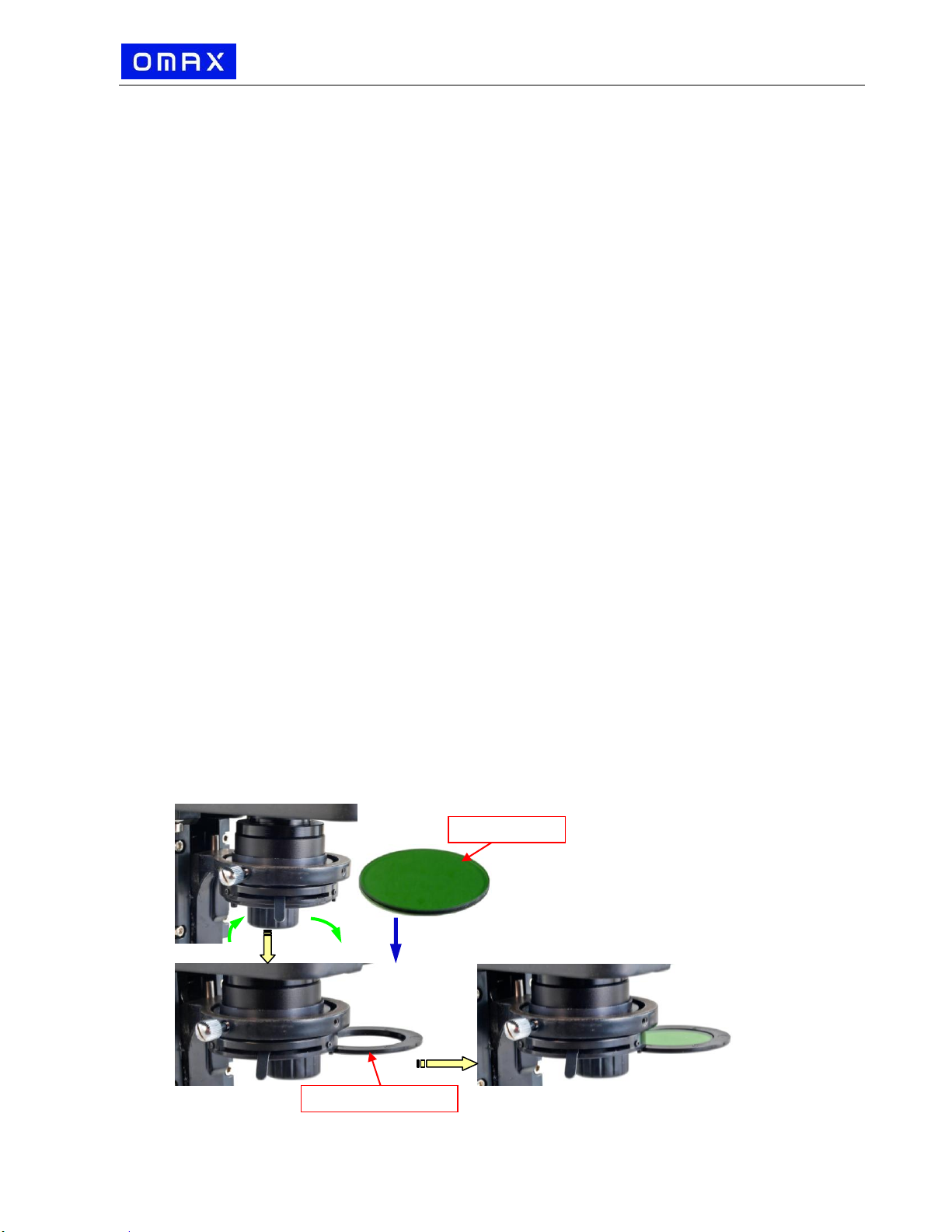
3.7 Adjusting iris aperture diaphragm
Swing the iris diaphragm lever (Fig.4) left or right to
adjust the aperture size.
Note:
The iris diaphragm is designed to adjust the aperture
size, not to adjust the brightness although the
brightness will be changed when it's adjusted. When
aperture is adjusted to smaller size, the contrast will
be increased and the depth of field will be increased
as well. Turn up the intensity of the light if the
image is too dim.
3.8 Adjusting focus knob tension
The tightness of the focus knob tension has
been pre-set at the factory. If the mechanical
stage drops by itself, rotate the tension
adjustment ring (Fig.5) located inside the focus
knob on the power switch side until the tension is
in maintained.
Fig.3
Iris Diaphragm Lever
Fig.4
Fig.5
Tension adjustment Ring
Focus Stop

www.microscopenet.com
7
4Specifications
General
Model
M8211E
Total Magnification
40X, 100X, 200X, 400X
Viewing Head
30ºinclined, 360ºswiveling siedentopf binocular viewing head
Interpupillary distance 1-7/8” ~ 2-15/16” (48mm ~ 75mm)
Adjustable diopter on left eyepiece tubes
Eyepieces
1 pair of WF10X/18
Objective Tube Length
160mm
Nosepiece
Reversed revolving quadruple
Objectives
Achromatic 4X, 10X, 20X(spring), 40X(spring)
Condenser
Abbe, NA=1.25, w/ iris aperture diaphragm and filter holder
Rack and pinion focus adjustment
Focus Mechanism
Coaxial coarse and fine focusing knobs on both sides w/ stop
Stage
Double layer mechanical stage
Dimension: 5-1/2”x 4-1/4” (140mm x 110mm)
Translation range: 3” x 1-9/16” (78mm x 40mm)
Illumination
Transmitted: replaceable 3W LED, variable intensity
Power Supply
AC 110V~240V, 50/60HZ (US and Canada plug)
Dimension
12-3/16” x 8” x 15-3/8” (31cm x 20.3cm x 39cm)
Net weight
11 lb 3.5 oz (5.09 kg)

www.microscopenet.com
8
5Troubleshooting Guide
Problem
Cause
Solution
Lamp does not light
when switched on
No electrical power
Check power cord connection
LED or power unit dead
Contact seller for service
Fuse blown out
Replace fuse
Darkness at the
periphery or uneven
brightness in the field
of view
Revolving nosepiece not in
click stop position
Revolve the nosepiece to click-stop
position by swinging the objective
correctly into the optical path
Dirt or dust on the view
Dirt or dust on the eyepiece,
condenser, objective,
collector lens or specimen
Clean the lens with a lens cleaning
paper
Poor image quality or
not able to get focused
image
No slide cover attached to
the slide
Attach a 0.17mm slide cover
Slide cover is too thick or thin
Use a slide cover of the appropriate
thickness (0.17mm)
Slide may be upside down
(specimen at the bottom)
Turn slide over so the cover-glass faces
up
Diopter adjustment is not set
properly
Readjust the diopter settings
Condenser aperture is closed
or open too much
Open or close properly
Condenser is positioned too
low
Position the condenser upward
Specimen rises from stage
surface
Secure the specimen in the slide holder
Revolving nosepiece is not in
the click-stop position
Revolve the nosepiece to the click-stop
position
Lamp intensity is too high or
low
Adjust the light intensity by rotating the
intensity control dial
Slippage of focus when
using the coarse
focusing knob Fine
focus is ineffective
Tension adjustment is set too
low
Increase the tension on the focusing
knobs
Tension adjustment is set too
high
Loosen the tension on the focusing
knobs
Table of contents
Other Omax Microscope manuals

Omax
Omax MAXJET 5i 320303 Series Instruction Manual

Omax
Omax M827S Series User manual

Omax
Omax M829 User manual

Omax
Omax M8333S User manual

Omax
Omax M828T User manual

Omax
Omax M827L Series User manual

Omax
Omax MD827S30 series User manual

Omax
Omax M8311Z Series User manual

Omax
Omax M827TL Series User manual

Omax
Omax M825 User manual