Omega ECD 15B User manual

Please read the following instructions carefully before installing electronic drain unit into
service. Trouble free and safe operating of the unit can only be guaranteed if
recommendations and conditions stated in this manual are respected.
Installation and operating
manual
ECD 15B / ECD 40B / ECD 90B / ECD 150B

ECD 15B / 40B / 90B / 150B - Installation and operating manual
2
Technical data
Please take the relevant climate zone into account when dimensioning yours specific ECD
series application.
Northern Europe, Canada, Northern USA, Central Asia
Central and Southern Europe, Central America
South East Asian coastal regions, Oceania, Amazon and Congo regions
Type
ECD 15B
ECD 40B
ECD 90B
ECD 150B
Voltage
115 VAC
115 V +/-10%
230 VAC
230 V +/-10%
Power
115 VAC
24 VA
230 VAC
24 VA
Frequency
50 – 60 Hz
Operation pressure range
0 – 16 bar / 0 – 232 psi
Drain capacity (7 bar / 101
psi)
15 l/h
0,0088 scfm
40 l/h
0,0235 scfm
90 l/h
0,0529 scfm
150 l/h
0,0882 scfm
Operating temperature
range
1,5 – 65°C 1,5 – 65°C 1,5 – 65°C 1,5 – 65°C
Inlet connection
G 1/2"
G 1/2"
G 1/2"
G 1/2"
Outlet connection
G 1/8"
G 1/8"
G 1/8"
G 1/8"
Power interface
3 x 0,75mm
2
3 x 0,75mm
2
3 x 0,75mm
2
3 x 0,75mm
2
Protection class
IP54
IP54
IP54
IP54
Volume
0,15 l
0,15 l
0,2 l
0,28 l
Mass
0,9 kg
0,9 kg
1,05 kg
1,15
Dimensions A x B x C [mm]
120 x 82 x 125
120 x 82 x 125
120 x 82 x 135
120 x 82 x 150
Peak Compressor
Performance
[m
3
/min]
11,6
29,4
60,6
111,6
9,3
23,5
48,5
89,3
5,8
14,7
30,3
55,8
Peak Dryer
Performance
[m
3
/min]
23,2
58,8
121,2
223,2
18,6
47,0
97,0
178,6
11,6
29,4
60,6
111,6
Peak Filter
Performance
[m
3
/min]
116
294
606
1116
93
235
485
893
58
147
303
558
Compressor power [kW]
Up to 30
Up to 75
Up to 160
Up to 315

ECD 15B / 40B / 90B / 150B - Installation and operating manual
3
Safety instructions
Depressurize the system before carrying out any work on the piping.
Installation and maintenance work may only be carried out when the device is
not under pressure.
Installation and maintenance work may only be carried out by trained and
experienced staff.
Disconnect power supply before installation or any maintenance work.
Electrical work must always be carried out by qualified electrician.
Do not exceed max. operating pressure or operating temperature range (see
data label).
Do not use the device in hazardous areas with potentially explosive
atmospheres.
Use original spare parts only.
Use the device for the appropriate purpose only.
Appropriate use
ECD series electronic condensate drain is intended exclusively for the following purpose:
Draining condensate from compressed air system (air compressors, air
receivers/pressure vessels, air dryers and air filters).
Any other form of use or one going beyond this shall be considered as inappropriate. We
shall have no liability whatsoever for any damage incurred as a result.

ECD 15B / 40B / 90B / 150B - Installation and operating manual
4
Operating
Condensate flows through inlet connection (1) and accumulates in the reservoir (2). Sensor
(3) is measuring condensate level. When reservoir (2) is detected full sensor (3) sends signal
to electronic board. Electromagnetic valve (4) is than opened to discharge accumulated
condensate through outlet connection (5). When reservoir (2) has been emptied, the valve
(4) closes back without any losses of compressed air.
Led signal is indicating status of the device (see Functions).
If microcontroller registers faulty operation, device goes to alarm mode. At the same time
signal is sent through voltage free contact (see Functions).
1
2
3
4
5

ECD 15B / 40B / 90B / 150B - Installation and operating manual
5
Installation
Inlet pipe (1) size at least ½” (inner diameter > 13mm).
Collecting condensate line (3) size at least ¾ “.
At least 1% inlet pipe slope recommended.
Install ball valves (2) only.
Recommended connection (4) to water/oil separator.
1
2
The inclination of the unit must not exceed + / - 5° in both axes. If device is not installed
correctly it could cause faulty detecting of condensate level.
3
4
Connecting several condensate sources to one drain device causes operating problems (3).
Make sure that each drain source has its own drain device (4).
1
2
3
4

ECD 15B / 40B / 90B / 150B - Installation and operating manual
6
5
6
Trapped air prevents the condensate being purged from drain (5). During installation ensure
that no water pockets are formed in the piping (6).
7
8
When drainage is to take place directly from a pipeline it is recommended to arrange the
piping so that air flow is diverted (8).
9
10

ECD 15B / 40B / 90B / 150B - Installation and operating manual
7
11
12
In case there are problems with inflow, it is necessary to install a venting line (12). In this
case back
connection is used as inlet and upper connection is used as air ventilation. Venting
line must never be installed as it is on pictures 9, 10 and 11.
Warning: Upper and back connections cannot be used as condensate inlet at the same
time.
13
14
STANDARD INSTALLATION
Upper connection = Inlet
Back connection = Closed
VENTING LINE INSTALLATION
Upper connection = Air ventilation
Back connection = Inlet
15
Electrical wiring
Please ensure that the installation is carried out according to the valid regulations
After installation or maintenance, the test button should be pressed to empty condensate that has been
collected while the ball valve has been closed.
Brown: L - Phase
Blue: N - Neutral
Yellow/Green: PE - Earth/Ground

ECD 15B / 40B / 90B / 150B - Installation and operating manual
8
Functions
LED indicator / TEST button
Power on
At power on there are few short green
flashes. These tell us ECD type.
1. One flash: ECD 15B
2. Two flashes: ECD 40B
3. Three flashes: ECD 90B
4. Four flashes: ECD 150B
Operating
LED indicates a condensate sensor output.
1. Green FLASHES: Sensor detects no
water
2. Green ON: Condensate is detected
3. Red ON: Alarm mode
Short flashes of red light indicate a
production mode. In this case, you should
contact producer.
By pressing TEST button valve opens.
Power On
ECD
Type
Reservoir empty
Reservoir full
Alarm
Green
Red
Power On
Production mode
Red

ECD 15B / 40B / 90B / 150B - Installation and operating manual
9
Operating modes
NORMAL
When sensor detects condensate the valve opens up to one second to discharge. The exact
period depends on type of a drain. Minimal time between two discharges is 5 seconds.
OVERLOAD
If sensor detects condensed water continuously for 90 seconds, drain enters overload mode.
In this mode, the valve is opened longer and the time between discharges is shorter.
Therefore, the amount of discharged condensate is doubled. This mode lasts for five
minutes. In case the reservoir empties during overload mode, the drain enters normal mode
again. Otherwise, it goes into alarm mode.
ALARM
If drain was still not able to discharge all condensate it enters alarm mode. In this mode, the
valve is opened for five seconds every half minute. In case the reservoir empties during
alarm mode, drain enters normal mode again.
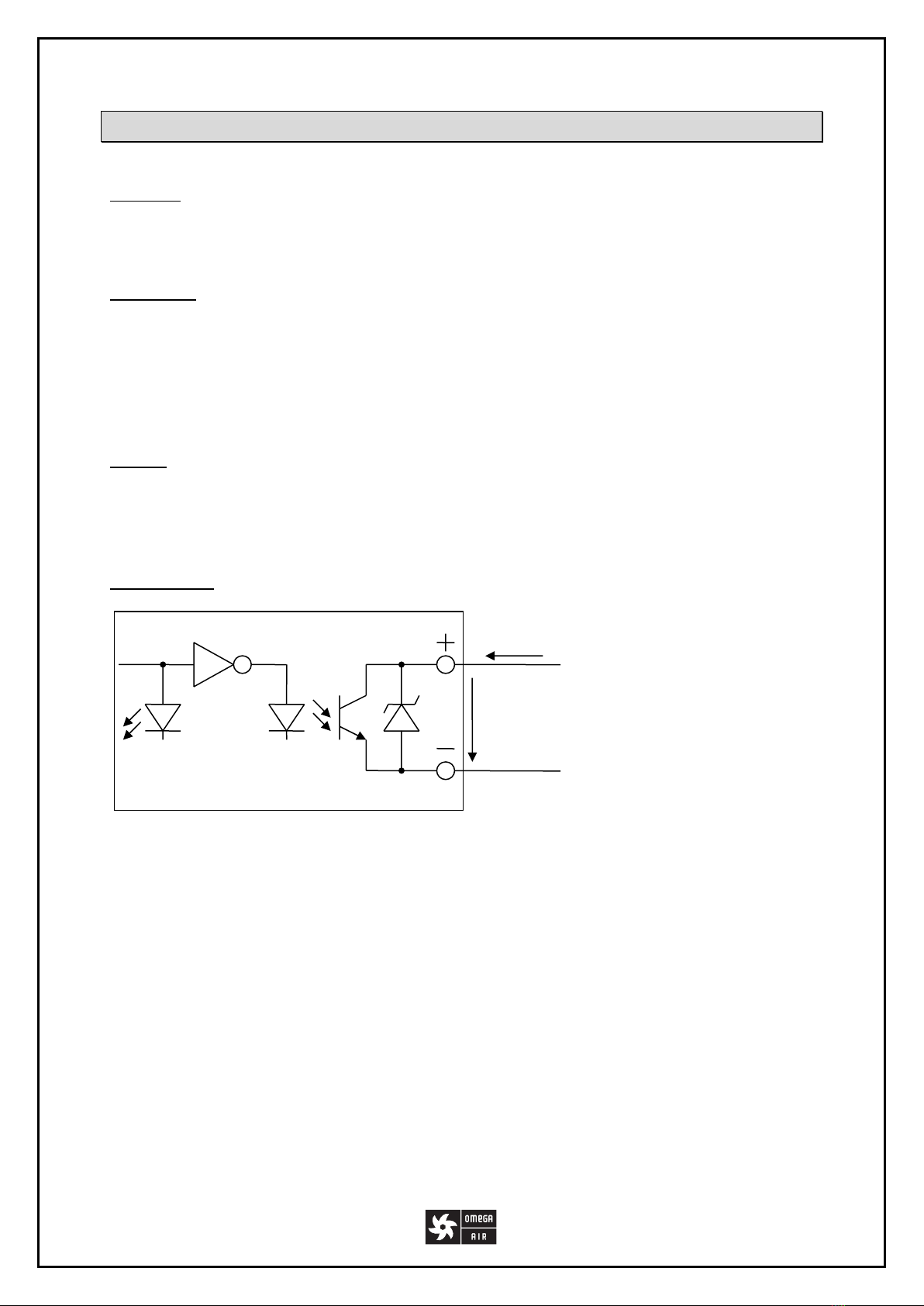
Alarm output
The ECD comprises an alarm output that is voltage free. The output is connected to the red
signal logically. The output is in high impedance state when the red LED is on or when ECD
electric supply is off.
Alarm
Red
LED
Alarm XA
U
OUT
I
OUT
(I
out
max 20mA)
(U
out
max 24V)

ECD 15B / 40B / 90B / 150B - Installation and operating manual
10
Maintenance
Service:
It is recommended to clean/change internal strainer and clean reservoir at least once a year.
Sealing elements are subject to wear, which depends on various operating parameters such
as pressure, temperature, dirt content, etc. It is also recommended to change sealings.
Attention
Before beginning maintenance work take the drain out of operation, cut off the power
supply and depressurize the unit.
Service kits
Service Kit type
Order number
Description
Service kit 1 – ECD 15B,40B
3400330
Servis kit
Service kit 1 – ECD 90B
3400331
Servis kit
Service kit 1 – ECD 150B
3400332
Servis kit
Operating data download
Electronic condensate drain ECD series stores operating data into EEPROM. Operating data
can be downloaded to determine condition of the device. For data reader please contact
supplier.

ECD 15B / 40B / 90B / 150B - Installation and operating manual
11
Components
Poz.
Part
1
Housing
2
Sensor husing
3
O-ring 15x1,5
4
Spacer 5x5
5
PCB
6
Washer M3 DIN6798A
7
Screw M3x10 DIN912
8
Damper
9
Plunger sealing
10
Spring base
11
Spring
12
Plunger
13
Valve housing
14
O-ring 5,8x1,5
15
Coil
16
O-ring 5,8x1,5
17
Valve connector
18
Screw M3 DIN912
19
Screw M3x30
20
Extension hose
21
Internal strainer
22
Sealing
23
O-ring 7x2
24
Bottom
25
Screw M5x16 DIN912
26
Screw plug ½”
27
Hose connector 6mm
28
Sensor
29
O-ring 30x2
30
Cable
31
Screw M5x8 DIN7500
32
Cover
33
Front panel label
34
High voltage label
35
Cable glant M16
36
Cap M16
37
Screw PT KA35x16
WN1411

ECD 15B / 40B / 90B / 150B - Installation and operating manual
12
Trouble shooting
Problem
Possible cause
Solution
No LED signal
Faulty or no power supply
PCB defective
Check power supply
Replace PCB
Pressing TEST
button has no
effect
Blocked valve
System pressure above 16bar /
232psi
Clean the valve
Check system pressure
Condensate
discharge only
when TEST button
is being pressed
Faulty installation
Condensate inlet line with
insufficient slope
Sensor extremely dirty
Check if device is installed in
accordance with installation
recommendations
Install venting line
Clean sensor housing
Air keeps blowing
out
Blocked valve
Wear
Clean the valve
Replace worn parts
Check if intense corrosion is
present in the system
Permanent red LED
flashes
Device is in one of production
modes
Contact supplier
Warranty exclusion
The guarantee shall be void if:
The installation and operating manual was not followed with respect to installation,
initial commissioning and maintenance.
The unit was not operated properly and appropriately.
The unit was operated when it was clearly defective.
Non-original spare parts or replacement parts were used.
The unit was not operated within the permissible technical parameters.
Unauthorized constructional changes were made to the unit or if the unit has been
opened/disassembled by an unauthorized person.
OMEGA AIR d.o.o. Ljubljana
Cesta Dolomitskega odreda 10
SI-1000 Ljubljana, Slovenia
Tel.: +386 (0)1 200 68 00
Fax.: +386 (0)1 200 68 50
E-mail: info@omega-air.si
www.omega-air.si
This manual suits for next models
3
Table of contents
Other Omega Industrial Equipment manuals
Popular Industrial Equipment manuals by other brands

Siemens
Siemens ET 200MP manual

CAT Pumps
CAT Pumps 7693 datasheet

ALL-FILL
ALL-FILL VF100e Installation & maintenance manual

YZ Systems
YZ Systems NJEX 7300L Instructions & operating manual

TriangleTube
TriangleTube Instinct 110 instruction manual

MIYAWAKI
MIYAWAKI RE3 Installation, operation & maintenance manual