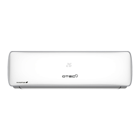
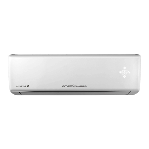
Omega OTEC IEWQ-R Series User manual

IEWQ(HQ)-R Series
High Wall Inverter
Service Manual

Service Manual
Table of Contents
Table of Contents
Part Ⅰ: Technical Information.......................................................................1
1. Summary......................................................................................................................1
3. Removal Procedure.......................................................................................26
3.1 Removal Procedure of Indoor Unit ................................................................26
3.2 Removal Procedure of Outdoor Unit.............................................................35
2.Troubleshooting ..................................................................................................2
2.1 Flashing LED of Indoor/Outdoor Unit and Primary Judgement ............2
2.2 Procedure of Troubleshooting ..........................................................................10
2.3 Troubleshooting for Normal Malfunction ......................................................24

1
Technical Information
Service Manual
1. Summary
Part Ⅰ: Technical Information
Indoor Unit
Outdoor Unit
IEWQ036J3A-RWI100
ICHQ036J3A-RLH100
Remote Controller:

35
Installation and Maintenance
Service Manual
2.Troubleshooting
2.1 Flashing LED of Indoor/Outdoor Unit and Primary Judgement
NO. Malfunction
Name
Display Method of Indoor Unit Display Method of Outdoor
Unit
A/C status Possible Causes
Dual-8
Code
Display
Indicator Display (during
blinking, ON 0.5s and OFF
0.5s)
Indicator has 3 kinds of
display status and during
blinking, ON 0.5s and OFF
0.5s
Operation
Indicator
Cool
Indicator
Heating
Indicator
Yellow
Indicator
Red
Indicator
Green
Indicator
1
High
pressure
protection of
system
E1
OFF 3s
and blink
once
During cooling and drying
operation, except indoor
fan operates, all loads stop
operation.
During heating operation, the
complete unit stops.
Possible reasons:
1. Refrigerant was superabundant;
2. Poor heat exchange (including
and bad radiating environment );
Ambient temperature is too high.
2Antifreezing
protection E2
OFF 3S
and blink
twice
OFF 1S
and blink
3 times
During cooling and drying
operation, compressor and
outdoor fan stop while indoor
fan operates.
1. Poor air-return in indoor unit;
2. Fan speed is abnormal;
3. Evaporator is dirty.
3
In defect of
refrigerant F0
OFF 1S
and
blink
9 times
The Dual-8 Code Display will
show F0 and the complete unit
stops.
1.In defect of refrigerant;
2.Indoor evaporator temperature
sensor works abnormally;
3.The unit has been plugged up
somewhere.
4
High
discharge
temperature
protection of
compressor
E4
OFF 3S
and blink
4 times
OFF 1S
and blink
7 times
During cooling and drying
operation, compressor and
outdoor fan stop while indoor
fan operates. During heating
operation, all loads stop.
Please refer to the malfunction
analysis (discharge protection,
overload).
5Overcurrent
protection E5
OFF 3S
and blink
5
times
OFF 1S
and blink
5 times
During cooling and drying
operation, compressor and
outdoor fan stop while indoor
fan operates. During heating
operation, all loads stop.
1. Supply voltage is unstable;
2. Supply voltage is too low and
load is too high;
3. Evaporator is dirty.
6
Communi-
cation
Malfunction
E6
OFF 3S
and blink Always
6 ON
times
During cooling operation,
compressor stops while
indoor fan motor operates.
During heating operation, the
complete unit stops.
Refer to the corresponding
malfunction analysis.
7
High
temperature
resistant
protection
E8
OFF 3S
and blink
8
times
OFF 1S
and blink
6 times
During cooling operation:
compressor will stop while
indoor fan will operate.
During heating operation, the
complete unit stops.
Refer to the malfunction analysis
(overload, high temperature
resistant).
8EEPROM
malfunction EE
OFF 3S
and blink
15 times
OFF 1S
and blink
11 times
During cooling and drying
operation, compressor will stop
while indoor fan will operate;
During heating operation, the
complete unit will stop
Replace outdoor control panel AP1
9
Limit/
decrease
frequency
due to high
temperature
of module
EU
OFF 3S
and blink
6 times
OFF 3S
and blink
6 times
All loads operate normally,
while
operation frequency for
compressor is decreased
Discharging after the complete unit
is de-energized for 20mins, check
whether the thermal grease on
IPM Module of outdoor control
the radiator is inserted tightly.
If its no use, please replace control
panel AP1.
10
Malfunction
protection of
jumper cap
C5
OFF 3S
and blink
15 times
Wireless remote receiver and
button are effective, but can
not dispose the related
command
1. No jumper cap insert on
mainboard.
2. Incorrect insert of jumper cap.
3. Jumper cap damaged.
4. Abnormal detecting circuit of
mainboard.

36 Installation and Maintenance
Service Manual
NO. Malfunction
Name
Display Method of Indoor Unit Display Method of Outdoor
Unit
A/C status Possible Causes
Dual-8
Code
Display
Indicator Display (during
blinking, ON 0.5s and OFF
0.5s)
Indicator has 3 kinds of
display status and during
blinking, ON 0.5s and OFF
0.5s
Operation
Indicator
Cool
Indicator
Heating
Indicator
Yellow
Indicator
Red
Indicator
Green
Indicator
11 Gathering
refrigerant Fo
OFF 3S
and blink
1 times
OFF 3S OFF 1S
and blink and blink
1 times 17 times
When the outdoor unit receive
signal of Gathering refrigerant
,the system will be forced to
run under cooling mode for
gathering refrigerant
Nominal cooling mode
12
Indoor
ambient
temperature
sensor is
open/short
circuited
F1
OFF 3S
and blink
once
During cooling and drying
operation, indoor unit operates
while other loads will stop;
during heating operation,
the complete unit will stop
operation.
1. Loosening or bad contact of
indoor ambient temp. sensor and
mainboard terminal.
2. Components in mainboard fell
down leads short circuit.
3. Indoor ambient temp. sensor
damaged.(check with sensor
resistance value chart)
4. Mainboard damaged.
13
Indoor
evaporator
temperature
sensor is
open/short
circuited
F2
OFF 3S
and blink
twice
AC stops operation once
reaches the setting
temperature. Cooling, drying:
internal fan motor stops
operation while other loads
stop operation; heating: AC
stop operation
1. Loosening or bad contact of
Indoor
evaporator temp. sensor and
mainboard terminal.
2. Components on the mainboard
fall
down leads short circuit.
3. Indoor evaporator temp. sensor
damaged.(check temp. sensor
value
chart for testing)
4. Mainboard damaged.
14
Outdoor
ambient
temperature
sensor is
open/short
circuited
F3
OFF 3S
and blink
3 times
OFF 1S
and
blink
6 times
During cooling and drying
operating, compressor stops
while indoor fan operates;
During heating operation,
the complete unit will stop
operation
Outdoor temperature sensor
hasnt been connected well or
is damaged. Please check it by
referring to the resistance table for
temperature sensor)
15
Outdoor
condenser
temperature
sensor is
open/short
circuited
F4
OFF 3S
and blink
4 times
OFF 1S
and
blink
5 times
During cooling and drying
operation, compressor stops
while indoor fan will operate;
During heating operation,
the complete unit will stop
operation.
Outdoor temperature sensor
hasnt been connected well or
is damaged. Please check it by
referring to the resistance table for
temperature sensor)
16
Outdoor
discharge
temperature
sensor is
open/short
circuited
F5
OFF 3S
and blink
5 times
OFF 1S
and
blink
7 times
During cooling and drying
operation, compressor will sop
after operating for about 3
mins,
while indoor fan will operate;
During heating operation, the
complete unit will stop after
operating for about 3 mins.
1.Outdoor temperature sensor
hasnt been connected well or is
damaged. Please check it by
referring to the resistance table for
temperature sensor)
2.The head of temperature sensor
hasnt been inserted into the copper
tube
17
Limit/
decrease
frequency
due to
overload
F6
OFF 3S
and blink
for 6
times
OFF 1S
and
blink
3 times
All loads operate normally,
while
operation frequency for
compressor is decreased
Refer to the malfunction analysis
(overload, high temperature
resistant)
18
Decrease
frequency
due to
overcurrent
F8
OFF 3S
and blink
8 times
OFF 1S
and
blink
once
All loads operate normally,
while
operation frequency for
compressor is decreased
The input supply voltage is too low;
System pressure is too high and
overload

37
Installation and Maintenance
Service Manual
NO. Malfunction
Name
Display Method of Indoor Unit Display Method of Outdoor
Unit
A/C status Possible Causes
Dual-8
Code
Display
Indicator Display (during
blinking, ON 0.5s and OFF
0.5s)
Indicator has 3 kinds of
display status and during
blinking, ON 0.5s and OFF
0.5s
Operation
Indicator
Cool
Indicator
Heating
Indicator
Yellow
Indicator
Red
Indicator
Green
Indicator
19
Decrease
frequency
due to
high air
discharge
F9
OFF 3S
and blink
9 times
OFF 1S
and
blink
twice
All loads operate normally,
while
operation frequency for
compressor is decreased
Overload or temperature is too
high;
Malfunction of electric expansion
valve (EKV)
20
Limit/
decrease
frequency
due to
antifreezing
FH
OFF 3S
and blink
2 times
OFF 3S
and blink
2 times
OFF 1S
and
blink
4 times
All loads operate normally,
while operation frequency for
compressor is decreased
Poor air-return in indoor unit or fan
speed is too low
21
Voltage for
DC bus-bar
is too high
PH
OFF 3S
and blink
11 times
OFF 1S
and
blink
13 times
During cooling and drying
operation, compressor will stop
while indoor fan will operate;
During heating operation, the
complete unit will stop
operation.
1. Measure the voltage of position
L and N on wiring board (XT), if the
voltage is higher than 265VAC, turn
on the unit after the supply voltage
is increased to the normal range.
2.If the AC input is normal,
measure the voltage of electrolytic
capacitor C on control panel (AP1),
if its normal, theres malfunction
for the circuit, please replace the
control panel (AP1)
22
Voltage of
DC bus-bar
is too low
PL
OFF 3S
and blink
21 times
OFF 1S
and
blink
12 times
During cooling and drying
operation, compressor will stop
while indoor fan will operate;
During heating operation, the
complete unit will stop
1. Measure the voltage of position
L and N on wiring board (XT), if the
voltage is higher than 150VAC,
turn on the unit after the supply
voltage is increased to the normal
range.
2.If the AC input is normal,
measure the voltage of electrolytic
capacitor C on control panel (AP1),
if its normal, theres malfunction
for the circuit, please replace the
control panel (AP1)
23
Compressor
Min
frequence in
test state
P0
(during
blinking,
ON
0.25s
and OFF
0.25s)
(during
blinking,
ON
0.25s
and OFF
0.25s)
Showing during min. cooling or
min. heating test
24
Compressor
rated
frequence in
test state
P1
(during
blinking,
ON
0.25s
and OFF
0.25s)
(during
blinking,
ON
0.25s
and OFF
0.25s)
Showing during nominal cooling or
nominal heating test
25
Compressor
maximum
frequence in
test state
P2
(during
blinking,
ON
0.25s
and OFF
0.25s)
(during
blinking,
ON
0.25s
and OFF
0.25s)
Showing during max. cooling or
max. heating test

38 Installation and Maintenance
Service Manual
NO. Malfunction
Name
Display Method of Indoor Unit Display Method of Outdoor
Unit
A/C status Possible Causes
Dual-8
Code
Display
Indicator Display (during
blinking, ON 0.5s and OFF
0.5s)
Indicator has 3 kinds of
display status and during
blinking, ON 0.5s and OFF
0.5s
Operation
Indicator
Cool
Indicator
Heating
Indicator
Yellow
Indicator
Red
Indicator
Green
Indicator
26
Compressor
intermediate
frequence in
test state
P3
(during
blinking,
ON
0.25s
and OFF
0.25s)
(during
blinking,
ON
0.25s
and OFF
0.25s)
Showing during middle cooling or
middle heating test
27
Overcurrent
protection of
phase
current for
compressor
P5
OFF 3S
and blink
15 times
During cooling and drying
operation, compressor will stop
while indoor fan will operate;
During heating operation, the
complete unit will stop
operation.
Refer to the malfunction
analysis (IPM protection, loss
of synchronism protection and
overcurrent protection of phase
current for compressor.
28
Charging
malfunction
of capacitor PU
OFF 3S
and blink
17 times
During cooling and drying
operation, compressor will stop
while indoor fan will operate;
During heating operation, the
complete unit will stop
Refer to the part three—charging
malfunction analysis of capacitor
29
Malfunction
of module
temperature
sensor circuit
P7
OFF 3S
and blink
18 times
During cooling and drying
operation, compressor will stop
while indoor fan will operate;
During heating operation, the
complete unit will stop
Replace outdoor control panel AP1
30
Module high
temperature
protection
P8
OFF 3S
and blink
19 times
During cooling operation,
compressor will stop while
indoor fan will operate;
During heating operation, the
complete unit will stop
After the complete unit is de-
energized for 20mins, check
whether the thermal grease on IPM
Module of outdoor control panel
radiator is inserted tightly. If its no
use, please replace control panel
AP1.
31
Decrease
frequency
due to high
temperature
resistant
during
heating
operation
H0
OFF 3S
and blink
10 times
All loads operate normally,
while
operation frequency for
compressor is decreased
Refer to the malfunction analysis
(overload, high temperature
resistant)
32
Static
dedusting
protection
H2
OFF 3S
and blink
twice
33
Overload
protection for
compressor
H3
OFF 3S
and blink
3 times
OFF 1S
and blink
8 times
During cooling and drying
operation, compressor will stop
while indoor fan will operate;
During heating operation, the
complete unit will stop
operation.
1. Wiring terminal OVC-COMP
is loosened. In normal state, the
resistance for this terminal should
be less than 1ohm.
2.Refer to the malfunction analysis (
discharge protection, overload)

39
Installation and Maintenance
Service Manual
NO. Malfunction
Name
Display Method of Indoor Unit Display Method of Outdoor
Unit
A/C status Possible Causes
Dual-8
Code
Display
Indicator Display (during
blinking, ON 0.5s and OFF
0.5s)
Indicator has 3 kinds of
display status and during
blinking, ON 0.5s and OFF
0.5s
Operation
Indicator
Cool
Indicator
Heating
Indicator
Yellow
Indicator
Red
Indicator
Green
Indicator
34 System is
abnormal H4
OFF 3S
and blink
4 times
OFF 1S
and blink
6 times
During cooling and drying
operation, compressor will stop
while indoor fan will operate;
During heating operation, the
complete unit will stop
operation.
Refer to the malfunction analysis
(overload, high temperature
resistant)
35 IPM
protection H5
OFF 3S
and blink
5 times
OFF 1S
and blink
4 times
During cooling and drying
operation, compressor will stop
while indoor fan will operate;
During heating operation, the
complete unit will stop
operation.
Refer to the malfunction
analysis (IPM protection, loss
of synchronism protection and
overcurrent protection of phase
current for compressor.
36
Internal motor
(fan motor) do
not operate
H6
OFF 3S
and blink
11 times
Internal fan motor, external fan
motor, compressor and electric
heater stop operation,guide
louver stops at present
location.
1. Bad contact of DC motor
feedback terminal.
2. Bad contact of DC motor
control end.
3. Fan motor is stalling.
4. Motor malfunction.
5. Malfunction of mainboard rev
detecting circuit.
37
Desynchro-
nizing of
compressor
H7
OFF 3S
and blink
7 times
During cooling and drying
operation, compressor will stop
while indoor fan will operate;
During heating operation, the
complete unit will stop
operation.
Refer to the malfunction
analysis (IPM protection, loss
of synchronism protection and
overcurrent protection of phase
current for compressor.
38 PFC
protection HC
OFF 3S
and blink
6 times
OFF 1S
and blink
14 times
During cooling and drying
operation, compressor will stop
while indoor fan will operate;
During heating operation, the
complete unit will stop
operation.
Refer to the malfunction analysis
39
Outdoor DC
fan motor
malfunction
L3
OFF 3S
and blink
23 times
OFF 1S
and
blink
14 times
Outdoor DC fan motor
malfunction lead to compressor
stop operation,
DC fan motor malfunction or
system blocked or the connector
loosed
40 power
protection L9
OFF 3S
and blink
20 times
OFF 1S
and blink
9 times
compressor stop operation and
Outdoor fan motor will stop
30s latter , 3 minutes latter
fan motor and compressor will
restart
To protect the electronical
components when detect high
power
41
Indoor unit
and outdoor
unit doesn't
match
LP
OFF 3S
and blink
19 times
OFF 1S
and blink
16 times
compressor and Outdoor fan
motor can’t work
Indoor unit and outdoor unit doesn't
match
42 Failure start-
up LC
OFF 3S
and blink
11 times
During cooling and drying
operation, compressor will stop
while indoor fan will operate;
During heating operation, the
complete unit will stop
operation.
Refer to the malfunction analysis

40 Installation and Maintenance
Service Manual
NO. Malfunction
Name
Display Method of Indoor Unit Display Method of Outdoor
Unit
A/C status Possible Causes
Dual-8
Code
Display
Indicator Display (during
blinking, ON 0.5s and OFF
0.5s)
Indicator has 3 kinds of
display status and during
blinking, ON 0.5s and OFF
0.5s
Operation
Indicator
Cool
Indicator
Heating
Indicator
Yellow
Indicator
Red
Indicator
Green
Indicator
43
Malfunction of
phase current
detection
circuit for
compressor
U1
OFF 3S
and blink
13 times
During cooling and drying
operation, compressor will stop
while indoor fan will operate;
During heating operation, the
complete unit will stop
Replace outdoor control panel AP1
44
Malfunction of
voltage
dropping for
DC bus-bar
U3
OFF 3S
and blink
20 times
During cooling and drying
operation, compressor will stop
while indoor fan will operate;
During heating operation, the
complete unit will stop
Supply voltage is unstable
45
Malfunction
of complete
units current
detection
U5
OFF 3S
and blink
13 times
During cooling and drying
operation, the compressor will
stop while indoor fan will
operate;
During heating operating,
the complete unit will stop
operation.
Theres circuit malfunction on
outdoor units control panel AP1,
please replace the outdoor units
control panel AP1.
46
The four-way
valve is
abnormal
U7
OFF 3S
and blink
20 times
If this malfunction occurs
during
heating operation, the complete
unit will stop operation.
1.Supply voltage is lower than
AC175V;
2.Wiring terminal 4V is loosened or
broken;
3.4V is damaged, please replace
4V.
47
Zero-
crossing
malfunction of
outdoor unit
U9
OFF 3S
and blink
18 times
During cooling operation,
compressor will stop while
indoor fan will operate; during
heating,the complete unit will
stop operation.
Replace outdoor control panel AP1
48
49
OFF 1S
and blink
once
50
51
Compressor
running
52
49
Anti-
freezing
protection
for
evaporator
E2
Not the error code. It’s
the status code for the
operation.
50
Cold air
prevention
protection
E9
Not the error code. It’s
the status code for the
operation.
51
Refrigerant
recovery
mode
Fo
Refrigerant recovery. The
Serviceman operates it for
maintenance

41
Installation and Maintenance
Service Manual
52
Malfunction
of detecting
plate(WIFI )
JF
Loads operate normally,
while the unit can’t be
normally controlled by
APP
1.Main board of indoor unit is
damaged;
2.Detection board is
damaged;
3.The connection between
indoor unit and detection
board is not good;
53 Defrosting
Heating
indicator
off for 0.5s
and then
blinks for
10s
Not the error code. It’s
the status code for the
operation.
54
Undened
outdoor unit
error
oE
Cool: compressor
and outdoor fan stops
operation, while indoor
fan operates; Heat:
compressor, outdoor
fan and indoor fan stop
operation.
1. Outdoor ambient
temperature exceeds the
operation range of unit (eg:
less than-20oC or more than
60oC for cooling; more than
30oC for heating);
2. Failure startup of
compressor?
3. Are wires of compressor
not connected tightly?
4. Is compressor damaged?
5. Is main board damaged?

42 Installation and Maintenance
Service Manual
Analysis or processing of some of the malfunction display:
1. Compressor discharge protection
Possible reasons: shortage of refrigerant; blockage of air lter; poor ventilation or air ow short pass for condenser;the system has
noncondensing gas (such as air, water etc.); blockage of capillary assy (including lter); leakage inside four-way valve causes incorrect
operation; malfunction of compressor; malfunction of protection relay; malfunction of discharge sensor; outdoor temperature too
high.
Processing method: refer to the malfunction analysis in the above section.
2. Low voltage overcurrent protection
Possible reason: Sudden drop of supply voltage.
3. Communic ation malfun ction
Processing method: Check if communic ation signal cable is connected reliably.
4. Sensor open or short circuit
Processing method: Check whethers ensor is normal, connected with the corre sponding position on the controller and if damage of
lead wire is found.
5. Compressor over load protection
Possible reasons: insufficient or too much refrigrant; blockage of capillary an dincrease of suction temp.; improper running of
compressor, burning in or stuck of bearing, damage of discharge valve; malfunction of protector.
Processing method: adjust refrige rant amount; replace the capillary; replace the compressor; use univers al meter to check if the
contactor of compress or is ne when it is not over heated, if not replace the protector.
6. System malfun ction
Overload protection.When tube temperature(Check the temperature of outdoor heat exchanger when cooling and check the
temperature of indoor heat exchanger when heating) is too high, protection will beactivated.
Possible reasons: Outdoor tempera ture is too high when cooling; insufcient outdoor air circulation; refrigerant ow malfunction.
Please refer to the malfunction analysis in the previous section for handling method .
7. IPM module protection
Processing method:Once the module malfunction happens,if it persists for a long time and can not be self-canceled, cut off the
power and turn off the unit,and then re-energize the unit again after about 10 min.After repeating the procedure for sever times, if
the malfunction still exists,replace the module.

43
Installation and Maintenance
Service Manual
2.2 Procedure of Troubleshooting
Indoor unit
(1) Malfunction of Temperature Sensor F1, F2
Main detection points:
● Is the wiring terminal between the temperature sensor and the controller loosened or poorly contacted?
● Is there short circuit due to trip-over of the parts?
● Is the temperature sensor broken?
● Is mainboard broken?
Malfunction diagnosis process:
Is the wiring terminal between the
temperature sensor and the controller
loosened or poorly contacted?
Start
Insert the temperature
sensor tightly
Yes
Yes
Yes
Yes
Yes
Yes
No
No
No
No
No
No
Is malfunction
eliminated
Is malfunction
eliminated
Is malfunction
eliminated
Replace it with a
temperature sensor with
the same model
Make the parts upright
Is there short circuit due to trip-
over of the parts
Is the temperature sensor normal
according to the resistance table?
Replace the mainboard with
the same model.
End

44 Installation and Maintenance
Service Manual
(2)
Malfunction of Blocked Protection of IDU Fan Motor H6
End
No
Yes
No
Ye
s
No
Yes
Yes
Yes
No
No
No
Yes
Yes
No
Turn the fan blades
by hand under
power-off condition
Whether the fan blades
can run smoothly?
Adjust the motor and blade
assembly so that rotor can run
smoothly.
Under power-off condition,
check whether the wiring terminal
between indoor fan and main
board is loose.
Turn unit on
to check whether the
malfunction is
eliminated.
Turn unit on
to check whether the
malfunction is
eliminated.
Reinsert the wiring
terminal of indoor fan.
It's the malfunction of main board.
Replace a new main board that is
of the same model.
It's the malfunction of main board.
Replace a new main board that is
of the same model.
Replace a new main board that is
of the same model.
It's the malfunction of main board.
Then check whether the voltage
between terminal 2 and terminal 3
of the motor interface is 15VDC.
Connect power and restart the unit.
Test whether the voltage between terminal 1 and terminal 2
of motor interface is within 280~310VDC.
Then check whether there is voltage
between terminal 2 and terminal 4
of the motor interface.
It's the malfunction of motor.
Replace a new motor that is
of the same model.
Start

45
Installation and Maintenance
Service Manual
3. Malfunction of Protection of Jumper Cap C5
Main detection points:
● Is there jumper cap on the mainboard?
● Is the jumper cap inserted correctly and tightly?
● The jumper is broken?
● The motor is broken?
● Detection circuit of the mainboard is dened abnormal?
Malfunction diagnosis process:
Start
Is there jumper cap on the mainboard?
Is the jumper cap inserted correctly
and tightly?
Replace the jumper cap with
the same model
Appearance of the
jumper cap
Assemble the jumper
cap with the same model
Insert the jumper
cap tightly
Is malfunction
eliminated
Is malfunction
eliminated
Is malfunction
eliminated
Replace the mainboard
with the same model
End
Yes
Yes
Yes
Yes
Yes
No
No
No
No
No

46 Installation and Maintenance
Service Manual
(4) Malfunction of detecting plate(WIFI) JF
Start
Is malfunction
eliminated
The end
check if the connection wire
are correctly connected
Replace the detecting
plate with the same model
Replace the mainboard
with the same model Yes
Yes
No
5. Malfunction of detecting plate(WIFI) JF

47
Installation and Maintenance
Service Manual
(5)
Communication malfunction (E6)
Disconnect power and check if
the connection wire of indoor
and outdoor units and the
built-in wire of electric box are
correctly connected.
Correct connection?
Connect the wire
properly according
to the wiring
diagram.
Is malfunction
eliminated?
Is malfunction
eliminated?
Is malfunction
eliminated?
Is malfunction
eliminated?
Main board matches with display
board? Main board of IDU
matches with that of ODU?
Match correctly
according to
product
specification.
Connection of communication
wire is damaged or not?
Replace the
connection wire.
Replace the main
board of IDU.
Replace the main
board of ODU.
End
No
No
No
No
No No
No
Yes
Yes
Yes
Yes Yes
Ye
s
Yes
Troubleshooting for E6
malfunction

48 Installation and Maintenance
Service Manual
Outdoot Unit
(1) Capacitor charge fault (Fault with outdoor unit) (AP1 below refers to the outdoor control panel)
Main
Check Points:
F
ault diagnosis process:
Use AC voltmeter to check if the voltage between terminal L and N on the wiring board is within 210VAC~240V
AC.
If the reactor (L) is correctly connected? If the connection is loose or fallen? If the reactor (L) is damaged?
N
Y
N
Y
N
Y
N
Y
N
Y
Turn on the unit
and wait 1 minute
Use DC voltmeter
to measure the
voltage on the two
ends of electrolytic
capacitor
Voltage higher than 200V?
Fault with the voltage
testing circuit on
control panel AP1
Replace the control
panel AP1
Measure the AC voltage between
terminal
L andN on wiring board
XT(power supply)
Voltage within
210VAC~250VAC?
Shut down the power
and repair the power
supply to restore the
range
210VAC~250VAC
power on and
restart the unit If the fault is
eliminated?
Shut down the power and wait 20 minutes;or
use DC voltmeter to measure the voltage
on the two ends of capacitor , until
the voltage is lower than 20V
Check the
connection of reactor
(L in the Electrical
Wiring Diagram)
If the wiring of
reactor L
is normal?
Connect the reactor
Laccording to Elec-
trical Wiring Diagr-
am correctly
Re-energize and
turn on the unit
If the fault is
eliminated?
End
Replace the control
panel AP1

49
Installation and Maintenance
Service Manual
2. IPM protection, phase current overcurrent (the control board as below indicates the control board
of outdoor unit) H5/P5
Mainly detect:
Troubleshooting:
Turn on the unit
after energization
Whether IPM
protection occurs after the unit has
operated for a while?
Measure the voltage
between terminal L
and terminal N with
AC volmeter
Whether
the voltage between
terminal L and terminal N of XT is
within 210AVC~
250VAC?
1. Whether the heat exchangers of indoor unit and outdoor unit are
dirty? Whether the radiation is affected because the unit is
covered by the objects?
2. When indoor fan and outdoor unit are operate normally?
3. Whether the system pressure is too high?
4. Whether the pressure is because there's too much refrigerant?
Check the power
supply voltage and
make the power voltage
resume to the range
of 210VAC~250VAC
Correctly connect the wires of
compressor according to the
electric wiring diagram, and
then turn on the unit
Check the connection
between the control board
and the compressor by
referring to the electric
wiring diagram
Check whether wires
of compressor (UVW) are connected
correctly
Measure the resistance value
among three terminals (UVW)
of compressor with a resistance
measuring meter.
Whether the
resistance value of three terminals
are almost the same.
Measure the resistance
between three terminals (UVW)
of compressor and the copper pipe
with resistance measuring meter
Whether the
resistance value is more than
500ohm?
Replace the
compressor
Whether there's
abnormal phenomenons
described as above?
Whether the unit
can operate normally?
Replace control
board
End
Correct it one by one
according to the Service
Manual, and then turn on
the unit.
(1) Compressor COMP terminal (2) voltage of power supply (3) compressor
(4) Refrigerant-charging volume (5) air outlet and air inlet of outdoor/indoor unit
(2).IPM protection, phase current overcurrent (the control board as below indicates the control board
of outdoor unit) H5/P5

50 Installation and Maintenance
Service Manual
(3)High temperature and overload protection diagnosis (AP1 hereinafter refers to the control board of the outdoor unit)
Mainly
detect:
Is outdoor ambient temperature in normal range?
Are the outdoor and indoor fans operating normally?
Is the heat dissipation environment inside and outside the unit is good?
Fault diagnosis process:
End
Y
Y
N
Y
N
N
Y
N
Overheat and high
temperature protection
Is outdoor ambient temperature higher than 53?
20 minutes after the complete
unit is powered off.
Is heat dissipation of the indoor unit
and outdoor unit abnormal?
Normal protection, please operate
it after the outdoor ambient temp-
erature is normalized.
Improve the heat
dissipation environ-
ment of the unit
Does the outdoor fan work normally?
1. Check if the fan terminal OFAN
is connected correctly
2.
Pull out needle stand of fan, and use
ohm's meter to measure the resistance
between any two termunals of the fan.
The resistance is lower than 1KOhm.
Replace the
control panel AP1
Replace the
outdoor fan

51
Installation and Maintenance
Service Manual
(4) Start-up failure (following AP1 for outdoor unit control board)
Mainly
detect:
Whether the compressor wiring is connected correct?
Is compressor broken?
Is time for compressor stopping enough?
F
ault diagnosis process:
Y
N
Y
N
N
Y
Y
N
Power on the unit
Is stop time of the compressor
longer than 3 minutes?
Restart it up after
3 minutes
Does startup fail?
Are the wires for the compressor connected
correctly? Is connection sequence right?
Connect the wires as
per the connection
diagram
Replace the control panel AP1
If the fault is eliminated?
Replace the
compressor
End
This manual suits for next models
3
Table of contents
Other Omega Inverter manuals
Popular Inverter manuals by other brands

opti-solar
opti-solar GT Series Installation and operation manual

Mitsubishi Electric
Mitsubishi Electric FR-A5AP instruction manual

Fujikura
Fujikura Dye-Sensitized Solar Cell user guide

SEW-Eurodrive
SEW-Eurodrive MOVIDRIVE compact Series System manual

Freedom Won
Freedom Won RL1 Series manual

Adleepower
Adleepower AP2G3-337 instruction manual