30
Installation and Maintenance
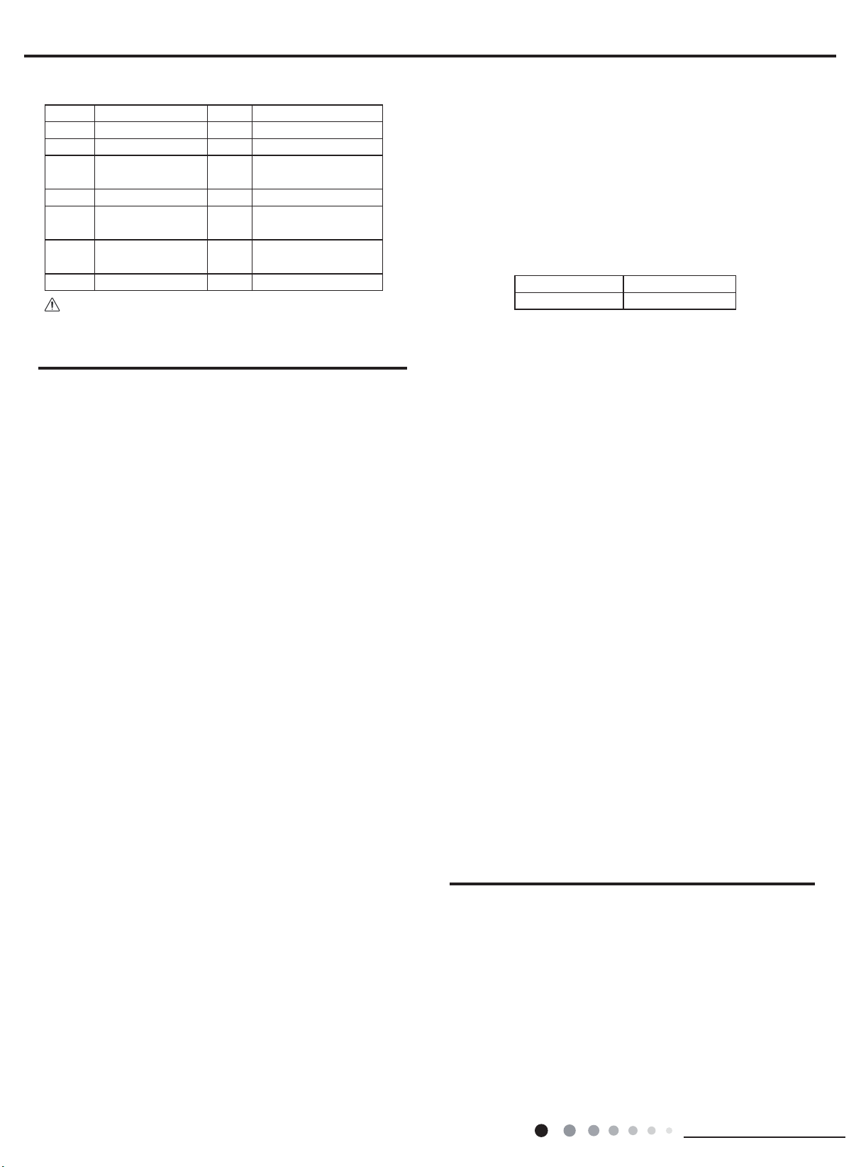
No. Name No. Name
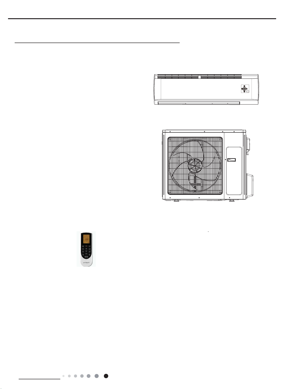
1 Indoor unit 8 Sealing gum
2 Outdoor unit 9 Wrapping tape
3 Connection pipe 10 Support of outdoor
unit
4 Drainage pipe 11 Fixing screw
5Wall-mounting
frame 12 Drainage plug(cooling
and heating unit)
6Connecting
cable(power cord) 13 Owners manual,
remote controller
7 Wall pipe
1. Safety Precaution
(1) Must follow the electric safety regulations when installing
the unit.
(2) According to the local safety regulations, use qualified
power supply circuit and air switch.
(3) Make sure the power supply matches with the requirement
of air conditioner. Unstable power supply or incorrect wiring
may result in electric shock,re hazard or malfunction. Please
install proper power supply cables before using the air
conditioner.
(4) Properly connect the live wire, neutral wire and grounding
wire of power socket.
(5) Be sure to cut off the power supply before proceeding any
work related to electricity and safety.
(6) Do not put through the power before nishing installation.
(7) If the supply cord is damaged, it must be replaced by the
manufacturer, its service agent or similary qualied persons in
order to aviod a hazard.
(8) The temperature of refrigerant circuit will be high, please
keep the interconnection cable away from the copper tube.
(9) The appliance shall be installed in accordance with national
wiring regulations.
3.2 Installation Parts-checking
3.3 Selection of Installation Location
3.4 Requirement For Electric Connection
3.5 Installation of Indoor Unit
Air-conditioner Air switch capacity
36K 25A
1.Please contact the local agent for installation.
2.Dont use unqualied power cord.
2. Grounding Requirement:
(1) The air conditioner is rst class electric appliance. It must
be properly grounding with specialized grounding device
by a professional. Please make sure it is always grounded
effectively, otherwise it may cause electric shock.
(2) The yellow-green wire in air conditioner is grounding wire,
which Can't be used for other purposes.
(3) The grounding resistance should comply with national
electric safety regulations.
(4) The appliance must be positioned so that the plug is
accessible.
(5) An all-pole disconnection switch having a contact separation
of at least 3mm in all poles should be connected in xed wiring.
(6) Including an air switch with suitable capacity, please note
the following table. Air switch should be included magnet
buckle and heating buckle function, it can protect the circuit-
short and overload. (Caution: please do not use the fuse only
for protect the circuit)
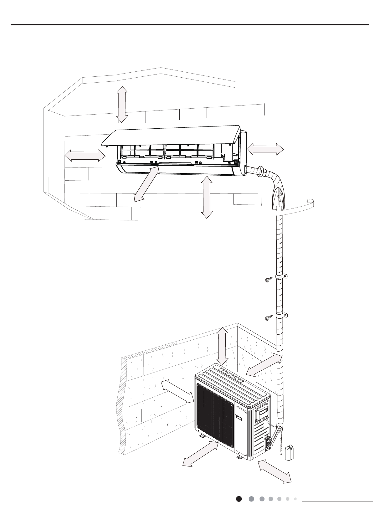
1. Choosing Installation Iocation
Recommend the installation location to the client and then
conrm it with the client.
2. Install Wall-mounting Frame
(1) Hang the wall-mounting frame on the wall; adjust it in
horizontal position with the level meter and then point out the
screw xing holes on the wall.
(2) Drill the screw xing holes on the wall with impact drill (the
specification of drill head should be the same as the plastic
expansion particle) and then ll the plastic expansion particles
2. Indoor Unit:
(1) There should be no obstruction near air inlet and air outlet.
(2) Select a location where the condensation water can be
dispersed easily andwont affect other people.
(3) Select a location which is convenient to connect the
outdoor unit and near the power socket.
(4) Select a location which is out of reach for children.
(5)
The location should be able to withstand
the weight of
indoor unit and wont increase noise and vibration.
(6)
The appliance must be installed 2.5m above oor.
(7) Dont install the indoor unit right above the electric
appliance.
(8) Please try your best to keep way from uorescent lamp.
3. Outdoor Unit:
(1) Select a location where the noise and outow air emitted by
the outdoor unit will not affect neighborhood.
(2) The location should be well ventilated and dry, in which
the outdoor unit wont be exposed directly to sunlight or strong
wind.
(3) The location should be able to withstand the weight of
outdoor unit.
(4) Make sure that the installation follows the requirement of
installation dimension diagram.
(5) Select a location which is out of reach for children and far
away from animals or plants.If it is unavoidable, please add
fence for safety purpose.
Note:
1. Basic Requirement:
Installing the unit in the following places may cause
malfunction. If it is unavoidable, please consult the local dealer:
(1) The place with strong heat sources, vapors, ammable or
explosive gas, or volatile objects spread in the air.
(2) The place with high-frequency devices (such as welding
machine, medical equipment).
(3) The place near coast area.
(4) The place with oil or fumes in the air.
(5) The place with sulfureted gas.
(6) Other places with special circumstances.
(7) The appliance shall not be installed in the laundry.
(8) It’s not allowed to be installed on the unstable or motive
base structure (such as truck) or in the corrosive
environment (such as chemical factory).