Vicruns VD520 Series User manual

Preface
Thank you for purchasing VD520 Series Inverters!
VD520 is a high-performance vector control inverter developed by VicRuns. Adopting advanced
vector control algorithm, it is widely used for asynchronous motor speed control. Through its
integrated EMC design and with optimized PWM control technique to meet users’ demand on
environmental requirement such as low-noise in application places and low EMI. It has perfect
anti-tripping control and good adaptive ability to bad power grid, temperature, humidity and dust, in
order to satisfy various sophisticated requirement under high precision drive applications, thus to
satisfy users expectation of higher reliability and stronger adaptability to environment of their
equipment, achieving industry specialization and personalized motor drive and control system
solution.
VD520 series high performance vector control inverter has following outstanding features:
1. Various control method
Supporting control method: SVC, V/F control.
2. Leading vector control algorithm
Optimized sensorless vector control has better low speed stability, stronger low frequency load
capacity, supporting speed control and torque control.
3. Support multi-function I/O extension and multi-function MFI extension port
Multi-function I/O extension card, multi-function MFI extension port can connect related extension
function unit defined by manufacturer.
This manual provides the related issues: user installing and site wiring, quick debug, parameters
setting, failure diagnose and eliminate and daily maintenance and correlation matters. Please read
this manual to make sure you can install, use and maintain the inverter correctly, then play their
superior performance.
Please send this manual to the user or maintainer of this inverter, and properly kept.
Unpacking and Inspection:
Every inverter has been inspected rigorously before shipping.
Please confirm carefully when unpacking the packing carton:
● Check if any damage signs of the product and its package.
● Check if the model and inverter rated values on the nameplate are the same as stated on your order
and user manual.
● The box contains the inverter, manufacturer certificate, user manual.
If the product is damaged during transportation, or there is any omission or damage, please contact
our company or your local supplier immediately.
First time use suggests:
The users who use this product for the first time shall read this manual carefully. For any doubt on
certain functions and performances, please contact the technical support personnel of our company
for help, so as to use this product properly. With commitment to the constant improvement of the
inverter products, our company may change the information provided without additional notice.
VD520 series inverter is confirmed to below international standard, has passed the CE certification.
IEC/EN 61800-5-1: 2003 adjustable speed electric drive system safety regulation requirements;
IEC/EN 61800-3: 2004 adjustable speed electric drive system: part 3: product EMC standard and its
specific test method;
IEC/EN61000-2-1, 2-2, 3-2, 3-3, 4-2, 4-3, 4-4, 4-5, 4-6; EMC international and EU standard .


Contents
Chapter 1 Safety and Precautions............................................................................................................- 1 -
1.1 Safety Definition...................................................................................................................................- 1 -
1.2 Safety Precautions...............................................................................................................................- 1 -
1.3 General Precautions............................................................................................................................- 3 -
Chapter 2 Product Information..................................................................................................................- 6 -
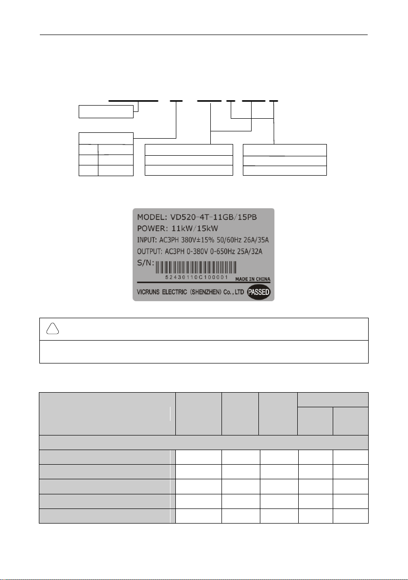
2.1 Designation Rules................................................................................................................................ - 6 -
2.2 Nameplate.............................................................................................................................................- 6 -
2.3 Inverter Series ...................................................................................................................................... - 6 -
2.4 Product Specifications .........................................................................................................................- 8 -
2.5 PhysicalAppearance and Main Structure Diagram........................................................................- 10 -
2.6 ProductAppearance and Installation Dimension............................................................................ - 11 -
2.7 Physical Dimensions of External Keyboard....................................................................................- 13 -
2.8 Braking Unit Model Selection Guide................................................................................................- 14 -
2.9 Routine Repair and Maintenance of Inverter.................................................................................. - 16 -
2.10 Warranty Introduction ......................................................................................................................- 17 -
Chapter 3 Mechanical and Electrical Installation..................................................................................- 18 -
3.1 Installation Environment....................................................................................................................- 18 -
3.2 The Installation Direction and Space............................................................................................... - 18 -
3.3 Removing and Mounting the Cover Plate and Keyboard..............................................................- 19 -
3.4 Inverter and External Electrical Parts Connection.......................................................................... - 20 -
3.5 Standard Wiring Diagram..................................................................................................................- 25 -
3.6 Main Circuit Terminals .......................................................................................................................- 27 -
3.7 Control Circuit Terminal..................................................................................................................... - 30 -
Chapter 4 Operation and Display........................................................................................................... - 38 -
4.1 Introduction to Operation and Display Interface.............................................................................- 38 -
4.2 Motor Parameter Self-learning.......................................................................................................... - 40 -
4.3 Password Setting ............................................................................................................................... - 41 -
4.4 Parameter Lock (authority lower than password)...........................................................................- 41 -
Chapter 5 Function Parameter Table .....................................................................................................- 42 -
Chapter 6 Parameter Description........................................................................................................... - 97 -
F0 Basic Function..................................................................................................................................... - 97 -
F1 Start/Stop Control Group.................................................................................................................. - 105 -
F2 Motor 1 Parameter............................................................................................................................ - 112 -
F3 Motor 1 Vector Control Parameter.................................................................................................. - 114 -
F4 Motor 1 V/F Control Parameter....................................................................................................... - 117 -
F5 Input Terminal Group........................................................................................................................ - 121 -
F6 Output Terminal Function Group.....................................................................................................- 131 -
F7 Keyboard and Display Function Group .......................................................................................... - 136 -
F8 Protection Parameters......................................................................................................................- 140 -
F9 Fault Record and Setting Parameter Group..................................................................................- 144 -
FA Process PID Parameter Group........................................................................................................ - 148 -
Fb Enhance Function Group.................................................................................................................- 153 -
Fd MODBUS Communication Parameter Group................................................................................- 169 -
FF User Parameters Group...................................................................................................................- 170 -
FP Factory Parameter Group................................................................................................................ - 172 -
A0 Motor 1 Torque Control Parameter Group .....................................................................................- 173 -
AI Optimize Control Parameter Group.................................................................................................- 176 -
A2, 3, 4 Motor 2 Parameter Function Group....................................................................................... - 178 -
b0 User Customize Function Code.......................................................................................................- 179 -
b1 Virtual IO Parameter Group .............................................................................................................- 180 -
b2 AI Curve Setting Parameter Group................................................................................................. - 184 -
b3 AIAO Correction Parameter Group .................................................................................................- 186 -
U0 Basic Monitoring Parameters Group.............................................................................................. - 188 -

Chapter 7 EMC Guide............................................................................................................................- 190 -
7.1 Definition............................................................................................................................................ - 190 -
7.2 EMC Standard Introduction............................................................................................................. - 190 -
7.3 EMC Guide........................................................................................................................................ - 190 -
Chapter 8 Fault Shooting and Solutions..............................................................................................- 192 -
8.1 Fault Alarm and Countermeasures................................................................................................ - 192 -
8.2 Common Faults and Solutions........................................................................................................- 196 -
Chapter 9 Communication Protocol......................................................................................................- 197 -
9.1 About Protocol..................................................................................................................................- 197 -
9.2 Application Methods.........................................................................................................................- 197 -
9.3 Bus Structure.................................................................................................................................... - 197 -
9.4 Protocol Description.........................................................................................................................- 197 -
9.5 Communication Frame Structure.................................................................................................... - 197 -
9.6 Command Code and Communication Data Description.............................................................. - 198 -
Fd MODBUS Communication............................................................................................................... - 205 -

VD520 Series Inverter User Manual Safety and Precautions
- 1 -
Chapter 1 Safety and Precautions
1.1 Safety Definition
During the installation, commissioning and maintenance of the system, please make sure to follow
the safety and precautions of this chapter. In case of a result of illegal operations, caused any harm
and losses is nothing to do with the manufacturer. In this manual, safety precautions are divided to
two types below:
DANGER
!
● Danger arising due to improper operations may cause severe hurt or even death and major
property damage.
WARNING
!
● Danger arising due to improper operations may cause moderate damage or light hurt, and
equipment damage or property damage.
1.2 Safety Precautions
1.2.1 Before Installation
DANGER
!
● Do not install the equipment if you find water seepage, component missing or damage upon
unpacking.
● Do not install the equipment if the packing list does not conform to the product you received
DANGER
!
● Handle the equipment with care during transportation to prevent damage.
● Do not touch the components with your hands. Failure to comply will result in static electricity
damage.
1.2.2 During Installation
DANGER
!
● Install the equipment on incombustible objects such as metal, and keep it away from combustible
materials. Failure to comply may result in a fire.
● Install the equipment according to regulations and tighten the fastening bolts. Failure to comply
may result in equipment falling.
● Do not loosen the fixed screws of the components, especially the screws with red mark.
WARNING
!
● Do not drop conductive objects as wire ends or screw into inverter. Failure to comply will result in
damages.
● Install inverter in place avoid to vibration, water drops and direct sunlight.

Safety and Precautions VD520 Series Inverter User Manual
- 2 -
● When two inverters are installed in the same cabinet, arrange the installation positions properly to
ensure normal cooling effect, keep the cabinet with good ventilation.
1.2.3 At Wiring
DANGER
!
● Wiring must be performed only by qualified personnel under instructions described in this manual.
Failure to comply may result in unexpected accidents.
● A circuit breaker must be used to isolate the power supply and inverter. Failure to comply may
result in a fire.
● Ensure that the power supply is cut off before wiring. Failure to comply may result in electric
shock.
● Connect inverter to ground properly by standard. Failure to comply may result in electric shock.
● Do not connect the input power with output terminals U, V, W, confirm the mark on terminal before
connection to avoid wrong wiring. Failure to comply can damage the inverter!
● Never connect the braking resistor between the DC bus terminals P+ and P-. Failure to comply
may result in a fire.
● The wire size of main circuit should conformed to standard, the wiring should comply with EMC
and local safety standard. Failure to comply may result in accidents.
● Use shielded cable for input output control circuit of analog and rapid speed pulse signal, and
ensure the shielding layer is reliably grounded.
1.2.4 Before Power-on:
DANGER
!
● Check that the following requirements are met:
● The voltage class of the power supply is consistent with the rated voltage class of the AC drive.
● The input terminals (R, S, T) and output terminals (U, V, W) are properly connected.
● No short-circuit exists in the peripheral circuit.
● The wiring is secured.
● The external units of inverter and wires are configured under the manual instructed, all matched
circuit and wiring are correctly connected.
● Failure to comply will result in damage to inverter!
1.2.5 After Power-on
DANGER
!
● Do not open the cover after inverter power-on to prevent electric shock.
● Do not touch or operate the inverter with wet hands. Failure to comply will result in electric shock.
● Do not touch any terminal of inverter after power-on, or drag connection cable. Failure to comply
will result in equipment damage or electric shock.
● Do not try to check or change the manufacturer parameter. Failure to comply may result in
malfunction or damage to inverter!
● Make sure the mechanical equipment is ready to start before inverter run with loading, make sure
related staff is in safety zone. Failure to comply will result in damage or personal hurt!
● Please pay attention to hiding accident which may result in personal hurt or property damage
while motor is run, if it is necessary to identify the motor parameter.

VD520 Series Inverter User Manual Safety and Precautions
- 3 -
1.2.6 During Operation
DANGER
!
● Do not touch the cooling fan or braking resistor etc, otherwise may cause personal injury!
● Do not do inspection while inverter run, except for professional technician, otherwise may cause
inverter damaged or personal injury.
WARNING
!
● Do not move inverter or the installed cabinet while it is run, keep external objects falling into the
device. Failure to comply will result in damage.
● Start/Stop inverter via terminal function or other control method, try not to start inverter via directly
power-on control method. Do not use contactor on inverter output terminal to control motor starting
or stop.
1.2.7 During Maintenance
DANGER
!
● Do not repair and maintain the equipment if power is connected. Otherwise there will be danger of
electric shock!
● If the LED is still on light on control panel, it is Disabled to disassemble the body in order to avoid
electric shock.
●The inverter shall be repaired and maintained only by the qualified person who has received
professional training. Otherwise, it may cause personal injury or equipment damage.
● For all the standard equipped or optional accessories, must be dismounted or mounted while the
inverter power is disconnected.
1.3 General Precautions
1.3.1 Motor Insulation Inspection
For first time usage, motor is left unused for long time or periodically inspected, insulation inspection
must be done to avoid motor coils insulation failure which may result in inverter damage. Disconnect
motor and inverter before inspection, 500V voltage type Meg-ohmmeter is recommended. It is up to
standard if insulation resist value no less than 5MΩ.
1.3.2 Motor Overheat Protection
If selected motor and inverter rated capacity doesn’t match, especially the inverter rated power larger
than motor rated power, it is necessary to adjust the motor protect parameter of inverter into actual
used motor parameter. Or a thermal relay can be installed to motor to protect motor.
1.3.3 Run with Power Frequency (under or above)
This inverter can provide 0.00Hz~650.00Hz output frequency, so motor is run at low frequency on
long time. Take care of motor cooling or frequency converted motor could be a choice. When motor
run with over-limit rate frequency, consider the bearing capacity of mechanic system with high speed,
to avoid the shortening of lifespan of equipment.
1.3.4 Vibration and Resonance of Mechanic System
Since inherent property of mechanic system, inverter could have mechanic system resonance point
while accelerating or decelerating, by setting inverter jump frequency can avoid mechanic system
resonance point. If customer required run frequency is happened to be the same with mechanic
resonance frequency, it is necessary to change run frequency or change the inherent resonance
frequency of mechanic system.

Safety and Precautions VD520 Series Inverter User Manual
- 4 -
1.3.5 Regarding Motor Heating and Noise
Inverter output voltage is PWM wave, with some higher harmonic, so motor temperature rising, noise
and vibration should increase a little comparing with power frequency, which is normal.
1.3.6 Pressure Sensing Device on Output Side or Improve Power Factor Capacitor
Inverter output voltage is PWM wave, if output side installed capacitor to improve power factor or
pressure sensing device to anti-thunder, it could easily result in instant over current or damage to
inverter. Disassemble such devices before inverter installation.
1.3.7 Switchover Device as Contactor Installed on Inverter Input Output Side
If there is a contactor between power supply and inverter input terminal, it is Disabled to use it to
start/stop inverter. When it is very necessary to use the contactor to start/stop inverter, the action
interval time should not less than 1hr. Since frequent charge/discharge could easily shorten the
lifespan of electrolytic capacitor inside inverter. If there is a contactor between motor and inverter
output terminal, make sure if motor is static and inverter is without output, then switchover the
contactor, failure to comply may damage the inverter.
1.3.8 Applications with Non-rated Voltage
The application voltage range used on inverter should not exceed the regulated voltage on this
manual, low voltage or higher voltage can easily damage inverter.
If power is not Enable, then use voltage reduction or voltage rising device to deal with voltage
conversion in order to comply with inverter input voltage requirement.
1.3.9 Three-phase Input Change to Two Phase Input
If inverter is 3phase input type, do not use 2phase power supply, otherwise it could result in phase
loss protection error even inverter damage.
1.3.10 Lightening Surge Protection
Although there is lightening overvoltage overcurrent device inside inverter, which has certain
self-protection function for lightening induction. But for user located in lightening frequent zones, it is
necessary to add lightening protection unit in front of inverter, this does good to extend inverter
lifespan.
1.3.11 Altitude Level and Voltage Reduction Usage
Place with altitude exceeding 2000M, inverter cooling effect get worse due to air condense reduced,
so under-rated usage of inverter is necessary.
1.3.12 Common DC Bus Introduction
In condition of several units of inverter run at the same time, then common DC bus can be adopted to
save electricity. This type of inverter support common DC bus, but make sure the power specification
of those inverters are very close in advance, otherwise it could damage inverter.
1.3.13 Precaution of Inverter Abandonment
Inverter belongs to electric electronic device, burning disposal will result lots of harmful gas even
exploding. Please refer to related national laws and regulations to dispose or abandon.
1.3.14 Regarding Adaptable Motor
①this type inverter standard matching motor is quaternary squirrel-cage asynchronous induction
motor or permanent magnet synchronous motor. When the dragging motor is not above type, please
refer to motor rated current to select the suitable inverter.
②the cooling fan of general motor and rotor spindle are coaxial connected. While motor rotating
speed reducing resulted cooling fan Deceleration proportionally and so making heat dissipation worse.
As a conclusion, if motor run at low frequency stage for long time, it is necessary to add a strong
exhaust fan or change the motor to variable frequency motor.
③Inverter default setup has built-in standard parameter for its adaptive motor, but in actual
application, it is necessary to identify motor parameter or change its original default setup of motor
parameter. Otherwise it affect operation efficiency and protection performance to motor.
④Due to cable or motor internal short circuit can result in inverter alarm or even exploding. So
insulation and short circuit test on wiring and motor should be done before connecting and installing
motor. If the system has been idled for long time, then a retest should be done to avoid system

VD520 Series Inverter User Manual Safety and Precautions
- 5 -
damage or performance reduce.

Product Information VD520 Series Inverter User Manual
- 6 -
Chapter 2 Product Information
2.1 Designation Rules
VD520-4T-11GB/15PB
Vicruns series
Adaptable moter power
G type 11kW moter
P type 15kW moter
Brake unit
B: Including brake unit
None
2S 220V
2T 220V
4T 380V
Voltage level
Fig 2.1-1 Designation Rules
2.2 Nameplate
Fig 2.2-1 Namepate
WARNING
!
● The bar code on inverter nameplate is the only code to recognize its identity, so the bar code is
the most important basis for the after sales service.
2.3 Inverter Series
Table 2-1 Product specifications and technical data
Model No.
Power
Capacity
(kVA)
Rated
Input
Current
(A)
Rated
Output
Current
(A)
Adaptable Motor
kW
HP
Single-phase Power supply: 220V, 50/60Hz
VD520-2S-0.7GB
1.5
8.2
4.0
0.75
1
VD520-2S-1.5GB
3.0
14.0
7.0
1.5
2
VD520-2S-2.2GB
4.0
23.0
9.6
2.2
3
VD520-2S-3.7GB
5.9
35.0
17.0
3.7
5
VD520-2S-5.5GB
8.9
50.0
25.0
5.5
7.5

VD520 Series Inverter User Manual Product Information
- 7 -
Three-phase Power supply:380V, 50/60Hz
VD520-4T-0.7GB
1.5
3.4
2.5
0.75
1
VD520-4T-1.5GB
3.0
5.0
3.8
1.5
2
VD520-4T-2.2GB
4.0
5.8
5.1
2.2
3
VD520-4T-3.7GB
5.9
10.5
9.0
3.7
5
VD520-4T-5.5GB
VD520-4T-5.5PB
8.9
14.6
13.0
5.5
7.5
VD520-4T-7.5GB
VD520-4T-7.5PB
11.0
20.5
17.0
7.5
10
VD520-4T-11GB
VD520-4T-11PB
17.0
26.0
25.0
11.0
15
VD520-4T-15GB
VD520-4T-15PB
21.0
35.0
32.0
15.0
20
VD520-4T-18.5G
VD520-4T-18.5PB
24.0
38.5
37.0
18.5
25
VD520-4T-22G
VD520-4T-22P
30.0
46.5
45.0
22
30
VD520-4T-30G
VD520-4T-30P
40.0
62.0
60.0
30
40
VD520-4T-37G
VD520-4T-37P
50.0
76.0
75.0
37
50
VD520-4T-45G
VD520-4T-45P
60.0
92.0
91.0
45
60
VD520-4T-55G
VD520-4T-55P
72.0
113.0
112.0
55
70
VD520-4T-75G
VD520-4T-75P
100.0
157.0
150.0
75
100
VD520-4T-90G
VD520-4T-90P
116.0
180.0
176.0
90
110
VD520-4T-110G
VD520-4T-110P
138.0
214.0
210.0
110
150
VD520-4T-132G
VD520-4T-132P
167.0
256.0
253.0
132
175
VD520-4T-160G
VD520-4T-160P
200.0
307.0
304.0
160
210
VD520-4T-185G
VD520-4T-185P
231.0
350.0
326.0
185
240
VD520-4T-200G
VD520-4T-200P
250.0
385.0
377.0
200
260
VD520-4T-220G
VD520-4T-220P
280.0
430.0
426.0
220
300
VD520-4T-250G
VD520-4T-250P
315.0
468.0
465.0
250
350
VD520-4T-280G
VD520-4T-280P
355.0
525.0
520.0
280
370
VD520-4T-315G
VD520-4T-315P
396.0
590.0
585.0
315
500
VD520-4T-355G
VD520-4T-355P
445.0
665.0
650.0
355
420
VD520-4T-400G
VD520-4T-400P
520.0
785.0
725.0
400
530
VD520-4T-450G
VD520-4T-450P
565.0
883.0
820.0
450
600
VD520-4T-500G
VD520-4T-500P
630.0
890.0
860.0
500
660
VD520-4T-560P
700.0
990.0
950
560
750

Product Information VD520 Series Inverter User Manual
- 8 -
2.4 Product Specifications
Table 2-2 Product technical specification
Item
Specifications
Power input
Rated input
voltage
Grade of rated voltage is 220V or 380V: voltage continued
fluctuation±10%, brief fluctuation:-15~+10%, voltage
imbalance rated<3%, aberration rate meet IEC61800-2
requirements.
Rated input
current
Refer to table 2-1
Rated frequency
50/60Hz, fluctuation range ±5%
Power output
Standard adaptive
motor
Refer to table 2-1
Rated capacity
Refer to table 2-1
Rated current
Refer to table 2-1
Output voltage
Output three-phase under the rated input condition,
0V~rated input voltage, error is less than±3%.
Main Control
Functions
Highest frequency
50.00Hz~600.00Hz
Carrier frequency
0.5kHz~16.0kHz, auto-adjust carrier frequency.
Input frequency
resolution
0.01Hz(digit setup mode)
Control mode
Open vector, V/F control
Start torque
0.25Hz/150%( vector control)
Motor type
asynchronous motor
Speed range
1: 100
Speed control
accuracy
±0.2%
Torque control
accuracy
5%
Overload capacity
G type motor: 150% rated current for 60sec; 200% rated
current for 1sec.
P type motor: 120% rated current for 60sec; 150% rated
current for 5sec.
Torque boost
Auto torque boost, manual torque boost by 0.1%~10.0%.
Acceleration/decel
eration curve
Linear or S curve acceleration/down mode, 4 types of
acceleration/down time, range 0.0s~6500.0s.
DC braking
DC braking frequency: .000Hz~max output frequency,
braking time: 0.0s~100.0s, braking current:
0.0%~100.0%.

VD520 Series Inverter User Manual Product Information
- 9 -
Main Control
Functions
Jogging control
Jogging frequency range: 0.00Hz~max output frequency,
jog Acceleration/down time 0.0s~3600.0s.
Easy PLC,
multi-stage speed
run
Via built-in PLC or control terminal can realize max 16
stage speed run.
Built-in PID
Can realize process control conveniently.
Auto-adjustment
of the voltage
Can keep the output voltage constant automatically when
the grid voltage changed.
Dynamic over
voltage
suppression
Auto suppress energy feedback value while run
frequency changes, prevent bus over current tripping off.
Oscillation
suppression
Optimize V/F oscillation arithmetic, realize V/F steady
operation.
Individual
Function
Power dip ride
through
It ensures that theAC drive continues to run for a short
time when an instantaneous power failure or sudden
voltage reduction occurs.
Timing control
Timing control function: setting time range:
0min-65535min.
Multi-motor
switchover
Two motors can be switched over via two groups of motor
parameters.
Support extension
Support multi-function I/O extension card
Operation
Running
command source
Operation panel, control terminals, serial communication
port, you can perform switchover between these sources
in various ways.
Frequency source
There are a total of 11 frequency sources, such as digital
setting, analog voltage setting, analog current setting,
pulse setting and serial communication port setting, panel
potentiometer setting, you can perform switchover
between these sources in various ways.
Auxiliary
frequency source
There are 11 auxiliary frequency sources, it can
implement fine tuning of auxiliary frequency and
frequency synthesis.
Input terminal
6 digit terminal input, 1 terminal support rapid pulse input
on max 100kHz.
2 analog input terminals; with optional 0/4mAto 20mA
current input or 0V to 10V voltage input.
Extension capacity: 3 digital input terminals and 1 analog
input terminals.
Output terminal
2 analog output terminals; with optional 0/4mA to 20mA
current output or -10V to 10V voltage output.
2 digit output terminals; one supporting
0.01KHz~100KHz square signal rapid pulse output.
2 relay output terminal
Extension capacity: 1 digit output terminal.

Product Information VD520 Series Inverter User Manual
- 10 -
Display and
Keypad
Operation
LED display
Can display 5 parameters
Protection
function
Motor short-circuit detection at power-on, input/output
phase loss protection, overcurrent protection,
overvoltage protection, undervoltage protection, overheat
protection and overload protection etc.
Environment
Installation
location
Indoor, free from direct, dust, corrosive gas, combustible
gas, oil smoke, vapor, drip or salt etc.
Altitude level
Lower than 2000m(de-rate if altitude is higher than
2000m).
Ambient
temperature
-10℃-+40℃(de-rate if the ambient temperature is
between 40℃and 50℃).
Humidity
<95%RH, without condensing..
Vibration
<5.9m/s2 (0.6g)
Storage
temperature
-20℃- +60℃
Protection grade
IP20
Cooling method
Forced air cooling
2.5 Physical Appearance and Main Structure Diagram
I/N Port
Fan
Front Housing Operationg Panel
Middle Structor
Bottom Housing
Inverter Nameplate
Inverter Mounting Hole
Fig 2.5-1 PhysicalAppearance and Main structure diagram

VD520 Series Inverter User Manual Product Information
- 11 -
2.6 Product Appearance and Installation Dimension
W
A D
H
B
Fig 2.6-1Schematic Diagram for Physical Dimensions and Mounting Dimensions (below 7.5kW)
W
A D
H
B
H1
Fig 2.6-2 Schematic Diagram for Physical Dimensions and Mounting Dimensions (11kW~110kW)
H
B
W
A
D
H1
W
H
D
Fig 2.6-3 Schematic Diagram for Physical Dimensions and Mounting Dimensions (up 132 kW)
Table 2-3 Physical Dimensions and Installation Hole(mm)

Product Information VD520 Series Inverter User Manual
- 12 -
Model
Mounting
Hole (mm)
Physical Dimensions ( mm)
Diameter
of
Mounting
Hole
(mm)
Weight
A
B
H
H1
W
D
d
kg
Single-phase 220V, 50/60Hz
VD520-2S-0.7GB
106.5
175
185
/
118
169
4.5
1.8
VD520-2S-1.5GB
VD520-2S-2.2GB
VD520-2S-3.7GB
148
235
247
/
160
191
5.5
3.0
VD520-2S-5.5GB
Three-phase 380V, 50/60Hz
VD520-4T-0.7GB
106.5
175
185
/
118
169
4.5
1.8
VD520-4T-1.5GB
VD520-4T-2.2GB
VD520-4T-3.7GB/5.5PB
VD520-4T-5.5GB/7.5PB
148
235
247
/
160
191
5.5
3.0
VD520-4T-7.5GB/11PB
VD520-4T-11GB/15PB
120
308
320
284
190
196.5
6.5
7.5
VD520-4T-15GB/18.5PB
VD520-4T-18.5G/22P
VD520-4T-22G/30P
180
396
412
372
260
216.5
8
13.5
VD520-4T-30G/37P
VD520-4T-37G/45P
VD520-4T-45G/55P
260
530
550
510
377
300
8
30
VD520-4T-55G/75P
VD520-4T-75G/90P
VD520-4T-90G/110P
350
670
690
640
450
330
9
55
VD520-4T-110G/132P
VD520-4T-132G/160P
350
850
870
810
450
330
9
60
VD520-4T-160G/185P
VD520-4T-185G/200P
400
875
900
1350
840
530
370
11
85
VD520-4T-200G/220P

VD520 Series Inverter User Manual Product Information
- 13 -
VD520-4T-220G/250P
500
970
1000
1450
940
700
395
13
125
VD520-4T-250G/280P
VD520-4T-280G/315P
VD520-4T-315G/355P
VD520-4T-355G/400P
560
1270
1300
1750
1240
800
415
13
200
VD520-4T-400G/450P
VD520-4T-450G/500P
VD520-4T-500G/560P
2.7 Physical Dimensions of External Keyboard
88
155
148
18
1378
Physical Dimensions of Keyboard Physical Dimensions of Keyboard holder
Fig 2.7-1 External keyboard and holder dimension
66.5
109.5
78.5
148.5
The mounting hole size of the card mounted The mounting hole size of the card mounted
when the keyboard does not add the tray when the keyboard add the tray
Fig 2.7-2 External keyboard and holder mounting dimension
70
114
66
109
14
40 50
82
17
17.5 25.5
2.5
2-M4

Product Information VD520 Series Inverter User Manual
- 14 -
LED
J6
CPU
+10V +5V
V
AA
A
V
AI2
AO1
V
AO2
+24VCOM
J15 J3J4J5 J14
J7
485+485-5/10V AI2 AO1 HDI1 DI2 T1/BT1/C
PEGND DI3GND DI1
AO2
AI1
T1/A
COM+24VOPENDI4
DI5COMHDO1 DO1 T2/A T2/C
+24V
COM
J19
● This inverter keyboard can be directly connected.
● A holder can be added to keyboard, but need to order separately.
2.8 Braking Unit Model Selection Guide
2.8.1 Resistor Value Selection
The regenerative energy of the motor is almost all consumed in the braking resistor when braking.
According to formula U*U/R=Pb
In formula U---braking voltage when system is stability braking (different system with different value,
for AC380V system, it generally take DC700V)
Pb----braking power
2.8.2 Braking Resistor Power Selection
Theoretically, braking resistor power is the same with braking power, but in consideration that the
de-rating is 70%,
According to formula: 0.7Pr=Pb*D
Pr----power of resistor
D----braking frequency (percentage of regenerating process account for the complete process)
Elevator----20%~30%
Uncoiling and recoiling----20%~30%
Centrifuge----50%~60%
Accidental braking loading----5%
General take 10% Table 2-4 Inverter braking unit selection
Model
Recommend
Power Braking
Resistor
Recommend
Resistance
Braking
Resistor
Braking
Unit
Remarks
Single-phase 220V 50/60Hz
VD520-2S-0.7GB
80W
≥150Ω
Internal
No special
instructions
VD520-2S-1.5GB
100W
≥100Ω
VD520-2S-2.2GB
100W
≥70Ω
VD520-2S-3.7GB
200W
≥40Ω
VD520-2S-5.5GB
300W
≥25Ω
Three-phase 380V 50/60Hz
VD520-4T-0.7GB
150W
≥300Ω
Internal
No special
instructions
VD520-4T-1.5GB
150W
≥220Ω
VD520-4T-2.2GB
250W
≥200Ω
VD520-4T-3.7GB/5.5PB
300W
≥130Ω
VD520-4T-5.5GB/7.5PB
400W
≥90Ω

VD520 Series Inverter User Manual Product Information
- 15 -
VD520-4T-7.5GB/11PB
500W
≥65Ω
Internal
No special
instructions
VD520-4T-11GB/15PB
800W
≥43Ω
VD520-4T-15GB/18.5PB
1000W
≥32Ω
VD520-4T-18.5G/22P
1300W
≥25Ω
VD520-4T-22G/30P
4.4kW
≥26.5Ω
External
VDBU-4T-70G
VD520-4T-30G/37P
6kW
≥19.4Ω
VD520-4T-37G/45P
7.4kW
≥15.8Ω
VD520-4T-45G/55P
9kW
≥13Ω
External
VDBU-4T-110G
VD520-4T-55G/75P
11kW
≥10.6Ω
VD520-4T-75G/90P
15kW
≥7.8Ω
VD520-4T-90G/110P
18kW
≥6.5Ω
External
VDBU-4T-160G
VD520-4T-110G/132P
22kW
≥5.3Ω
VD520-4T-132G/160P
26.4kW
≥4.4Ω
External
VDBU-4T-250G
VD520-4T-160G/185P
32kW
≥3.6Ω
VD520-4T-185G/200P
37kW
≥3.2Ω
External
VDBU-4T-330G
VD520-4T-200G/220P
40kW
≥2.9Ω
VD520-4T-220G/250P
44kW
≥2.7Ω
VD520-4T-250G/280P
50kW
≥2.3Ω
VD520-4T-280G/315P
56kW
≥2.1Ω
External
VDBU-4T-600G
VD520-4T-315G/355P
63kW
≥1.9Ω
VD520-4T-355G/400P
70kW
≥1.7Ω
VD520-4T-400G/450P
80kW
≥1.5Ω
VD520-4T-450G/500P
90kW
≥1.3Ω
External
VDBU-4T-800G
VD520-4T-500G/560P
100kW
≥1.2Ω
WARNING
!
● Table 2-4 is a guide data, user can select different resistor value and power according to actual
situation.
● Selection of braking resistor is based on the motor generation power in actual application system,
it is related with system inertia, deceleration time, potential load energy, it is decided by user’s
actual situation.
● The greater the inertia of system, the required speed deceleration is shorter, the braking is more
frequent, so the braking resistor require a bigger power small value of resistor.

Product Information VD520 Series Inverter User Manual
- 16 -
2.9 Routine Repair and Maintenance of Inverter
The influence of the ambient temperature, humidity, dust and vibration will cause the aging of the
devices in the inverter, which may cause potential fault of the inverter or reduce the service life of the
inverter. Therefore, it is necessary to carry out routine and periodical maintenance on the inverter, it
must be regularly maintenance for every 3~6 months.
2.9.1 Daily Round Check
Daily Inspection Projects
WARNING
!
● If the heat from motor and the run inverter is higher than normal temperature
● If any abnormal noise or vibration from motor and the run inverter
● If current value of inverter loading current is as normal level
● If inverter cooling fan is run as normal, if it is stained with oil dirt and speed getting low.
● If the color of main control circuit terminal changed or rusted, if any arc discharge between input
and output phases.
● If the enclosure of inverter is overheat, if inverter inside is filled with dirt ormetal powder, or oil dirt
on circuit board or conductive copper bar etc.
● If inverter is installed in cabinet, good ventilation is kept, cooling fan is run as normal.
2.9.2 Regular Maintenance
Regular maintenance item
WARNING
!
● Clear inverter cooling air duct regularly, once the speed of cooling fan inside cabinet getting low
or stop, then replace it on time.
● Check if the connecting screws in main circuit and control circuit is loosed, any signs of overheat
on connecting copper bar inside inverter.
● Check if the insulation performance of motor and main circuit cable, any insulation damage of
main circuit and control circuit, especially the surface contacting with metal has cut.
● Non-professional staff or untrained operator cannot do maintenance or change device of the
inverter, failure to comply will result in personal hurt or damage the device.
● User is required to do insulation test on inverter. While testing insulation resistor of motor and
cable, make sure to disconnect inverter in advance. Otherwise the inverter can be damaged.
● If user insist to do insulation test on inverter, make sure all the input output terminal of main
circuit (L, N, R, S, T, U, V, W, P1, P+, PB, P-) are reliably grounded, use a 500V Meg Ohm Meter to
check.
● Do not use a 500V meg ohm meter to check on control circuit terminal, otherwise it can damage
inverter.
2.9.3 Inverter Wearing Part Replacement
Some device inside inverter can get wearing or aged after using for a certain period, in order to
ensure inverter operate reliably, it is necessary to do preventive maintenance, when necessary some
device need to be replaced.
The wearing part of inverter mainly as cooling fan, filtering big capacity electrolytic capacitor. Those
life is closely related with its applicant environment and maintain condition.
This manual suits for next models
58
Table of contents
Other Vicruns Inverter manuals
Popular Inverter manuals by other brands

Shihlin electric
Shihlin electric SE2 Series manual

Samil Power
Samil Power SolarRiver 4500TL-G3 manual

Maxeon
Maxeon SPR-P6-555-UPP installation instructions

ABB
ABB PVS-175-TL-US Quick installation guide

Airwell
Airwell DLSE Series Service manual

Centrosolar
Centrosolar Powerstocc ExcellentSeries Short manual

Xantrex
Xantrex PV-225208 Operation and maintenance manual

Selectronic
Selectronic SPMC240 Technical bulletin

TECO-Westinghouse
TECO-Westinghouse A510 instruction manual

Tektronix
Tektronix SG 504 instruction manual

Goodwe
Goodwe POLARIS Series installation manual

Latronics
Latronics PV Edge Grid Connect instruction manual