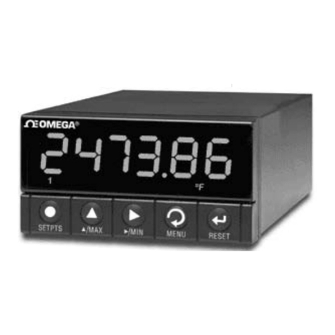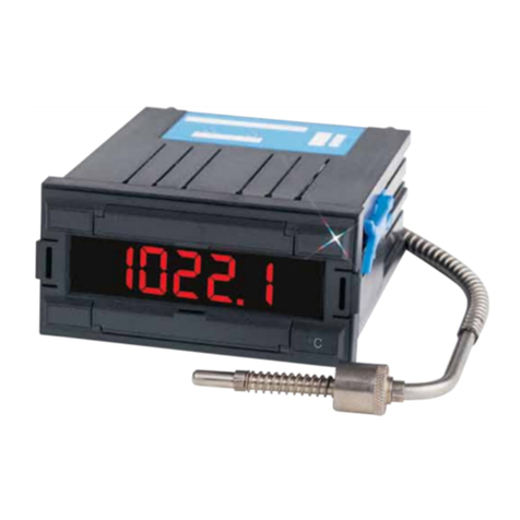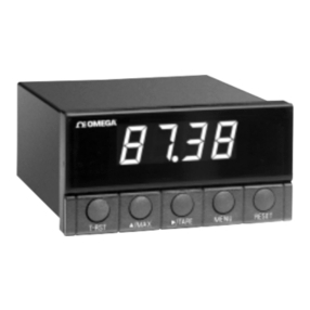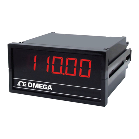
DP18 Series
96
(3.78)
44.5
(1.75)
48
(1.89)
MECHANICALDIMENSIONSmm(in)
D3 = 1.XXX
D2 = 1X.XX
D1 = 1XX.X
DECIMALPOINTSSELECTOR
D3 D1D2
INSTALL THE JUMPER IN
THE INDICATED PLACE,
ACCORDING TO THE
RANGESELECTED.
SIGNAL
CONDITIONER
(solderside)
MOTHERBOARD
COMPONENTS
SIDE
POWER SUPPLY
CONNECTOR
FIG.6
FIG.4
FIG.5
SELECTIONOF:DECIMALPOINTSANDSPECIALOPTIONS
OPTIONSANDPOWERSUPPLIESAVAILABLEFORDP18Series
BCD PARALLELBCD,OPTOISOLATED A01 ANALOGOUTPUT,mA SINK
R1 SINGLESETPOINT,3Amp.Relay A02 ANALOG OUTPUT,mASOURCE
R2 DUALSETPOINT,3Amp:Relays A03 ANALOGOUTPUT,VOLTAGE
APH1 ANALOGPEAKHOLD APH2 ANALOGPEAKHOLD
232 ISOLATEDSERIALOUTPUTRS-232
OPTION DESCRIPTION OPTION DESCRIPTION OPTION POWER OPTION POWER
CONTROLOUTPUT/COMMUNICATIONSOPTIONS
Select a maximum of one option from each column POWERSUPPLYOPTIONS
115
115
230
AL
J1
J2
JUMPERS SELECTION FOR SPECIAL OPTIONS
AL:OPEN ONLYWHENALARMSETPOINT CARDOPTIONIS ADDED
J1: OPENTOELIMINATETHELEAST-SIGNIFICANTDIGIT(LSD)
J2: OPENTOELIMINATETHE INDICATION ±
PANELCUTOUT
CONNECTOR FOR ANALOG OUTPUT
(OPTIONAL)
13
(0.51)
102
(4.02) 15
(0.59)
5 max. (0.20)
92.5
(3.64)
230 230Vac 50/60Hz
STD 115 Vac 50/60 Hz 15/30Vdc 15...30Vdc.-10%(3.5W)
24 24Vac 50/60Hz 24/65Vdc 24...65 Vdc(4 W) isolated
48 48Vac 50/60Hz
isolated
MOTHERBOARD
SOLDERSIDE
An OMEGA Te ch nolo gie s Co m p an y
Servicing USA and Canada: Call OMEGA Toll Free
USA Canada
OneOmegaDrive,Box4047 976Bergar
Stamford,CT06907-0047 Laval(Quebec)H7L5A1
Telephone:(203)359-1660 Telephone:(514)856-6928
FAX:(203)359-7700 FAX:(514)856-6886
SalesService:1-800-826-6342/1-800-TC-OMEGASM
CustomerService:1-800-622-2378/1-800-622-BESTSM
EngineeringService:1-800-872-9436/1-800-USA-WHENSM
TELEX:996404 EASYLINK:62968934 CABLE:OMEGA
Servicing Europe: One OMEGA Drive, River Bend
Thecnology Centre
Northbank,Irlam,Manchester
M44 5EX,England
Telephone:44(161)777-6611 FAX:44(161)777-6622
RETURNREQUESTS/INQUIRIES
Direct all warranty and repair requests/inquiries to the OMEGA ENGINEERING Customer
ServiceDepartment.BEFORERETURNINGANYPRODUCT(S)TOOMEGA,PURCHASER
MUSTOBTAINANAUTHORIZEDRETURN(AR)NUMBERFROMOMEGA'SCUSTOMER
SERVICEDEPARTMENT(INORDERTOAVOIDPROCESSINGDELAYS).TheassignedAR
numbershouldthenbemarkedontheoutsideofthereturnpackageandonanycorrespondence.
OMEGA'spolicyistomakerunningchanges,notmodelchanges,wheneveranimprovementis
possible.Thisaffordsourcustomersthelatestintechnologyandengineering.
OMEGAisaregisteredtrademarkofOMEGAENGINEERING,INC.
©Copyright1998OMEGAENGINEERING,INC.Allrightsreserved.Thisdocumentationmaynot
becopied,photocopied,reproduced,translated,orreducedtoanyelectronicmediumormachine-
readableform,inwholeorinpart,withoutpriorwrittenconsentofOMEGAENGINEERING,INC.
FORWARRANTYRETURNS,pleasehave
thefollowinginformationavailableBEFORE
contactingOMEGA:
1. P.O.numberunderwhichtheproductwas
PURCHASED.
2. Model and serial number of the product
underwarranty,and
3. Repairinstructionsand/orspecificprob-
lemsrelativetotheproduct.
WARRANTY/DISCLAIMER
OMEGA warrants this unit to be free of defects in materials and workmanship and to give
satisfactoryserviceforaperiodof13monthsfromdateofpurchase.OMEGAWarrantyaddsan
additional one (1)month grace period tothe normal one (1) year product warranty tocover
handlingandshippingtime.ThisensuresthatOMEGA'scustomersreceivemaximumcoverage
oneachproduct.Iftheunitshouldmalfunction,itmustbereturnedtothefactoryforevaluation.
OMEGA'sCustomerServiceDepartmentwillissueanAuthorizedReturn(AR)numberimme-
diatelyuponphoneorwrittenrequest.Upon examinationbyOMEGA,iftheunitis foundtobe
defectiveitwillberepairedorreplacedatnocharge.However,thisWARRANTYisVOIDifthe
unitshowsevidenceofhavingbeentamperedwithorshowsevidenceofbeingdamagedasaresult
of excessive corrosion; or current; heat; moisture or vibration; improper specification;
misapplication;misuse orotheroperatingconditionsoutsideofOMEGA'scontrol.Components
whichwearorwhicharedamagedbymisusearenotwarranted.Theseincludecontactpoints,
fusesandtriacs.
.
OMEGA is pleased to offer suggestions on the use of its various products.
However OMEGA neither assumes responsability for any omissions or errors
nor assumes liability for any damages that result from the use of its products
in accordance with information provided by OMEGA, either verbal or written.
OMEGAonlywarrants thatthe partsmanufacturedby itwill be asspecified and
free of defects. OMEGA MAKES NO OTHER WARRANTIES OR REPRESENTA-
TIONSOFANY KIND WHATSOEVER,EXPRESSED OR IMPLIED,EXCEPTTHAT
OF TITLE AND ALL IMPLIED WARRANTIES INCLUDING ANY WARRANTY OF
MERCHANTABILITY AND FITNESS FOR A PARTICULAR PURPOSE ARE
HEREBY DISCLAIMED.
LIMITATION OF LIABILITY: The remedies of purchaser set forth herein are
exclusive and the total liability of OMEGA with respect to this order, whether
based on contract, warranty, negligence, indemnification, strict liability or
otherwise, shall not exceed the purchase price of the component upon which
liabilityis based.InnoevenshallOMEGAbe liablefor consequential,incidental
orspecialdamages.
CONDITIONS:Equipment soldbyOMEGAisnotintendedtobeused,norshallitbeused:(1)as
a"BasicComponent"under10CFR21(NRC),usedinorwithanynuclearinstallationoractivity;
or(2)inmedicalapplicationsorused onhumans.ShouldanyProduct(s)beusedinorwithany
nuclear installation or activity, medical application, used in humans, or misused in any way.
OMEGA assumes no responsibility as set forth in our basic WARRANTY/DISCLAIMER lan-
guage,and,additionally,purchaserwillindemnifyOMEGAandholdOMEGAharmleesfromany
liabilityordamagewhatsoeverarisingoutoftheuseoftheProduct(s)insuchamanner.
FOR NON-WARRANTY REPAIRS, consult
OMEGAforcurrentrepaircharges.Havethe
followinginformationavailableBEFORE
contactingOMEGA:
1. P.O.numbertocovertheCOSTofthe
repair,
2. Modelandserialnumberof product,and
3. Repairinstructionsand/orspecific
problemsrelativetotheproduct.

