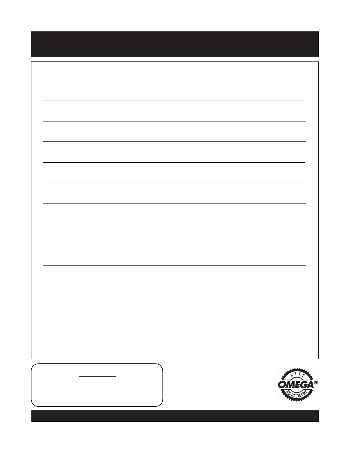
Omega 46000 Instructions for use

This is the safety alert symbol. It is used to alert you to potential personal injury hazards.
Obey all safety messages that follow this symbol to avoid possible injury or death.
!
Read this manual and follow all the Safety Rules and Operating Instructions before using this product.
!ADVERTENCIA
• Leer, comprender, y seguir las instrucciónes antes
de utilizar el aparato.
• El manual de instrucciónes y la información de
seguridad deben estar comunicado en lengua del
operador antes del uso.
• No seguir estas indicaciónes puede causar daños
personales o materiales.
Printed in China
46000-M2 rev 05/10
Operating Instructions & Parts Manual
SFA Companies
http://www.omegalift.com
!WARNING
To avoid crushing and related injuries:
•
NEVER work on, under or around
a load supported only by a hydraulic
jack.
•
ALWAYS use adequately rated jack
stands.
!Rated capacity has not been established by the
manufacturer of this device! Extraordinary care
must be taken to avoid overloading!
Brake Drum Handler
Model: 46000

2
!
SPECIFICATIONS
Model Min. Bed Height Max. Bed Height Product Size
(L X W X H)
46000 10-5/8" 15" 61-3/8" X 19-5/8" X 17-5/8"
Do not use this device for any purpose other than that for which it is expressly intended.
SAFETY and GENERAL INFORMATION
Save these instructions. For your safety, read, understand, and follow the information provided with and on this
equipment before using. The owner and operator of this equipment shall have an understanding of this it and of
safe operating procedures before attempting to use. The owner and operator shall be aware that the use and repair
of this product may require special skills and knowledge. Instructions and safety information shall be conveyed in
the operator's native language before use is authorized. If any doubt exists as to the safe and proper use of this
equipment, remove from service immediately.
Inspect before each use. Do not use if broken, bent, cracked or damaged parts are noted. Any Brake Drum
Handler that appears damaged in any way, or operates abnormally shall be removed from service immediately. If
this equipment has been subjected to a shock load (a load dropped suddenly, unexpectedly upon it), immediately
discontinue use until it has been checked by a factory authorized service center (contact distributor or manufacturer
for list of authorized service centers). It is recommended that an annual inspection be done by qualied personnel.
Labels and Operator's Manuals are available from manufacturer.
PRODUCT DESCRIPTION
The Omega Brake Drum Handler is specically designed to engage, secure, and transport from an axle assembly,
an unfastened and loose brake drum/hub assembly. It is not designed to act as a puller and should be relied upon
to ONLY handle brake drum/hub assemblies which nest within the holding arms and side frames of the Brake Drum
Handler as seen in Figs 2, 3.
Handle Grip
Handle
Hook Bracket
(drum / hub
assy. position
shown)
Bed Height /
Angle Control
Wheel
Holding Arm
Handle Lock Pin
Hook Lock Pin
Handle Fork
Drum Handler
Frame
Wheel Axle
Bed
Figure 1 - Model 46000 Nomenclature
BEFORE USE
1. Read and understand instructional and warning
materials provided with and on this product.
2. Verify that the product and the application are com-
patible, if in doubt contact Technical Service @ (888)
332-6419.
3. Thoroughly familiarize yourself with this product, its
components, and the hazards associated with its
use.
4. Inspect drum handler before each use. Do not use
if bent, broken or cracked components are noted.
Ensure that all parts move freely.
5. Consult the vehicle manufacturer's service manual
for proper preparation and procedures for removing
& installing a drum / hub assemblies.
!Rated capacity has not been established by the
manufacturer of this device! Extraordinary care
must be taken to avoid overloading! Bending, bowing,
or cracked components are visible evidence of over-
loading. If such deformation is noted, STOP, imme-
diately discontinue use and transfer load to a drum
handler of greater capacity.

3
ASSEMBLY
(refer to gure 4 on page 4)
1. Thread the connecting block (#12) to middle rod (#6),
then secure to base (#3) with M10 nut and washer
(#21 & 22).
2. Secure top cover (#4) and two holding arms (#14) to
base (#3) with M6x25 bolts, washers & nuts (#15,
16 & 17)
3. Attach wheel axle (#5) to base (#3) with M12x40 bolts
& nuts (#23 & 24)
4. Attach wheels (#18) and washers (#19) to wheel axle
(#5), then secure with cotter pins (#20)
5. Secure the axle links (#5A) of wheel axle (#5) to
connecting block (#12) with M12 bolts and washers
(#13 & 19).
6. Attach hook bracket (#9) to top cover (#4) and secure
with lock pin (#11)
7. Attach angle adjustable wheel (#7) to middle rod (#6)
with set screw (#8).
8. Attach handle (#1) to top cover (#4) with lock pin
(#2).
9. Insert handle grip (#10) to handle (#1).
OPERATION
1. Prepare the brake drum or brake drum/hub assembly
for removal according to the instructions in vehicle
service manual.
2. Place drum handler in a horizontal position.
3. Turn the angle adjustable wheel until the drum han-
dler is in its lowest postion.
4. Position the handler under the drum until the holding
arms meet the outer surface of the drum.
5. Turn the angle adjustable wheel clockwise until the
handler meets the lower surface of the drum.
6. Lower the handle to slightly lift the drum. Pull the
handler and drum back, away from the brake as-
sembly.
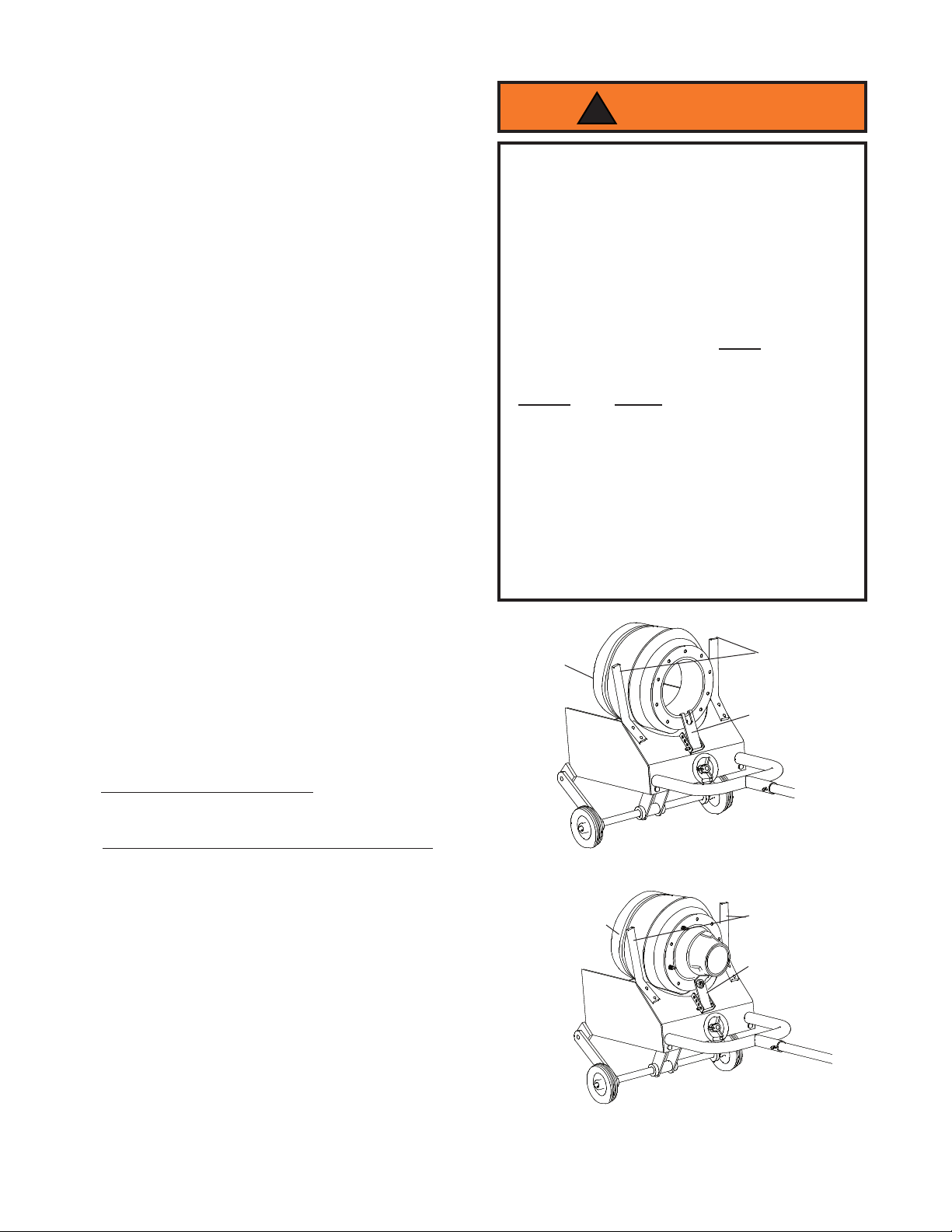
7. Removing/installing drum only:
Flip the hook bracket into the hub opening of the
drum as shown in gure 2.
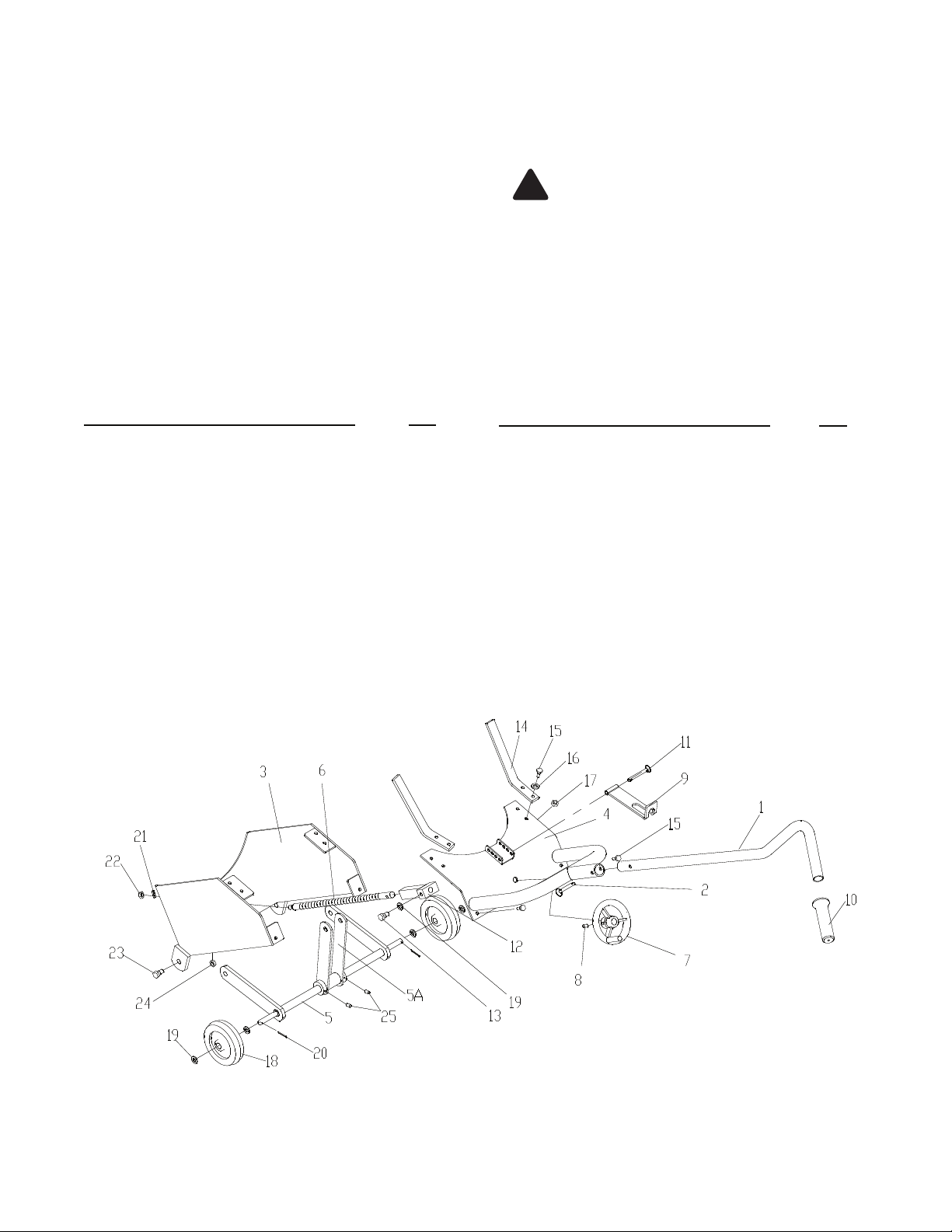
Removing/installing drum and hub as assembly:
Position the hook bracket reverse as shown in gure
3 to allow a wheel nut to secure hook to drum/hub
assembly.
8. It may be necessary to adjust the hook. Remove the
hook lock pin, and move the hook bracket to any one
of four hole locations.
9. Pull the drum completely away from the brake as-
sembly. Slowly and carefully lift the handle to place
the drum face down on the oor, being cautious of
the transfer of load weight.
Note: Reverse the process to Install the brake drum
back to the brake assembly. Be sure to align the drum
with the studs and follow the instructions in the vehicle
service manual.
Hook Position
(for drum only)
Figure 2 - Illustration for removing/installing drum
Brake Drum
Holding Arms
Hook Position
(for drum/hub
assy.)
Drum/Hub Assy.
Figure 3 - Illustration for removing/installing drum/hub
assembly
Holding Arms
• Study, understand, and follow all printed mate-
rials provided with and on this device before use.
• Ensure that vehicle is chocked, lifted, and sup-
ported by adequately rated jack stands before
using this product!
• Use only for removal, installation, and transport
of brake drum/hub assys which nest and can be
secured within the bed frame and holding arms.
• DO NOT overload. Bending, bowing, or cracked
components are visible evidence of overloading.
If such deformation is noted, STOP, immediately
discontinue use and transfer load to a drum han-
dler of greater capacity.
• Secure drum before transporting.
• Use only on hard, level surface.
• Raise and lower the brake drum slowly.
• Always wear steel-toed shoes when using this
device.
• Brake drum dust is hazardous to your health.
Consult Federal, State and local regulations con-
cerning the safe handling of asbestos and what
precautions to take when handling.
• Failure to heed these markings may result in
personal injury and/or property damage.
WARNING
!

4
MAINTENANCE
Periodically inspect the drum handler. Ensure all parts
move freely.
When not in use, store drum handler in upright position
and in a clean, dry area.
Figure 4 - Replacement Parts Illustration
Lubrication
A periodic coating of light lubricating oil to pivot points,
axles and hinges will help to prevent rust and assure
that assemblies move freely.
Paint contains lead!
DO NOT sand or grind painted surface!
!
Replacement Parts for Omega 46000
Item# Part# Description Qty.
1 T230-00001-000 Handle 1
2 T230-06000-000 Lock Pin 1
3 N/A Base 1
4 T230-02000-000 Top Cover 1
5 T230-04000-000 Wheel Axle 1
6 T230-00003-000 Middle Rod 1
7 T230-08000-000 Adjustable Wheel 1
8 * Screw 1
9 T230-01000-000 Hook Bracket 1
10 T230-00006-000 Handle Grip 1
11 T230-07000-000 Lock Pin 1
12 T230-05000-000 Connecting Block 1
13 T230-00004-000 Hex Bolt M12 2
14 T230-00002-000 Holding Arm 2
15 * Hex Bolt M6x25 6
Item# Part# Description Qty.
16 * Washer 6
17 * Nut M6 6
18 T230-00005-000 Wheel 8" 2
19 * Washer 6
20 * Cotter Pin 2
21 * Washer 1
22 * Nut M10 1
23 * Hex Bolt M12x40 2
24 * Nut M12 2
25 * Set Screw 2
(*) T230-09000-000 Hardware Kit -
Hardware Kit includes item# 8, 15, 16, 17,
19, 20, 21, 22, 23, 24 & 25
REPLACEMENT PARTS
Not all components of the drum handler are replacement items, but are illustrated as a convenient reference of
location and position in the assembly sequence. When ordering parts, give Model number, serial number and parts
description. Call or write for current pricing: SFA Companies Inc. 10939 N. Pomona Ave. Kansas City, MO 64153,
U.S.A. Tel:(888)332-6419 Fax:(816)891-6599 E-Mail:[email protected]
Omega Website: http://www.omegalift.com

ONE YEAR LIMITED WARRANTY
For a period of one (1) year from date of purchase, SFA Companies will repair or replace, at its option,
without charge, any of its products which fails due to a defect in material or workmanship under normal usage. This
limited warranty is a consumer's exclusive remedy.
Performance of any obligation under this warranty may be obtained by returning the warranted product, freight
prepaid, to SFA Companies Warranty Service Department, 10939 N. Pomona Ave., Kansas City, MO 64153.
Except where such limitations and exclusions are specically prohibited by applicable law, (1) THE
CONSUMER'S SOLE AND EXCLUSIVE REMEDY SHALL BE THE REPAIR OR REPLACEMENT OF DEFECTIVE
PRODUCTS AS DESCRIBED ABOVE. (2) SFA Companies SHALL NOT BE LIABLE FOR ANY CONSEQUENTIAL
OR INCIDENTAL DAMAGE OR LOSS WHATSOEVER. (3) ANY IMPLIED WARRANTIES, INCLUDING WITHOUT
LIMITATION THE IMPLIED WARRANTIES OF MERCHANTABILITY AND FITNESS FOR A PARTICULAR
PURPOSE, SHALL BE LIMITED TO ONE YEAR, OTHERWISE THE REPAIR, REPLACEMENT OR REFUND AS
PROVIDED UNDER THIS EXPRESS LIMITED WARRANTY IS THE EXCLUSIVE REMEDY OF THE CONSUMER,
AND IS PROVIDED IN LIEU OF ALL OTHER WARRANTIES, EXPRESS OR IMPLIED. (4) ANY MODIFICATION,
ALTERATION, ABUSE, UNAUTHORIZED SERVICE OR ORNAMENTAL DESIGN VOIDS THIS WARRANTY AND
IS NOT COVERED BY THIS WARRANTY.
Some states do not allow limitations on how long an implied warranty lasts, so the above limitation may not
apply to you. Some states do not allow the exclusion or limitation of incidental or consequential damages, so the
above limitation or exclusion may not apply to you. This warranty gives you specic legal rights, and you may also
have other rights, which vary from state to state.
SFA Companies
10939 N. Pomona Ave. Kansas City, MO 64153
888-332-6419
5

Note Page
Contact:
SFA Companies
10939 N. Pomona Ave. Kansas City, MO 64153, U.S.A.
Tel:(888)332-6419 Fax:(816)891-6599
E-Mail:[email protected]
Omega Website: http://www.omegalift.com

Note Page
Contact:
SFA Companies
10939 N. Pomona Ave. Kansas City, MO 64153, U.S.A.
Tel:(888)332-6419 Fax:(816)891-6599
E-Mail:[email protected]
Omega Website: http://www.omegalift.com

Note Page
Contact:
SFA Companies
10939 N. Pomona Ave. Kansas City, MO 64153, U.S.A.
Tel:(888)332-6419 Fax:(816)891-6599
E-Mail:[email protected]
Omega Website: http://www.omegalift.com
Table of contents
Other Omega Storage manuals

Omega
Omega Security Module User manual

Omega
Omega HDS-Plus User manual

Omega
Omega FFC18362CH User manual

Omega
Omega Security Cage with Aluminum Truck Dolly User manual

Omega
Omega Post-Type Wall Mount Shelving User manual

Omega
Omega Solid Stainless Steel Shelving User manual

Omega
Omega Direct Mounted Wall Shelf User manual