Omega Post-Type Wall Mount Shelving User manual

ASSEMBLY
INSTRUCTIONS
continued on backside
Post-Type Wall Mount Shelving
Material List
Each post contains 2 mounting
brackets (top & bottom) and bolts to secure
bracket to the post ends
Each post mount bracket includes 1 pair of plastic
sleeves and 2 chrome plated shelf caps
33˝ Posts have 1 intermediate bracket
54˝ Posts have 2 intermediate brackets
63˝ Posts have 3 intermediate brackets
Step 1 Unpack carton to confirm all necessary components are included.
Step 2 Determine the desired height and location of the unit.
Then mark the center points for all brackets of the unit
being mounted. Be certain the points are in direct line
vertically and horizontally. This is essential for shelf or
shelves to be mounted correctly.
Step 3 Prepare mounting holes. Mounting screws or bolts
are not supplied with units due to varied types of walls
or supports these units are to be mounted on. It is the
responsibility of the user to make certain that the mounting
surface and the method of mounting is suitable and
sufficient to support the anticipated weight that will be
placed on the unit. Each intermediate and mounting bracket
has two 11/32˝ diameter clearance holes for mounting.
Step 4 Remove the bolts from the ends of the posts.
SAVE THESE BOLTS
Step 5 The bottom of the post is the end which has the longest
distance between the first groove and the end of the post.
Count from the bottom of the post and place plastic split
sleeves (See Diagram #1) onto groove where you would like
the first post mount bracket located.
Step 6 Slide the post mount bracket down from the top of the
post onto the plastic split sleeves. (See Diagram #2)
Step 7 If a two, three, or four tier unit is being assembled, slide
down an intermediate bracket.
Step 8 For a two, three, or four tier unit repeat steps 5, 6, and 7
until all brackets have been mounted.
Step 9 Repeat steps 4 through 8 for the remaining post(s)
DIAgRAM 1 DIAgRAM 2

ASSEMBLY INSTRUCTIONS
rev. 0311
DIAgRAM 3 DIAgRAM 4
Step 10 Secure the post mount brackets by gently hitting them with a rubber mallet or using a hammer and
block of wood. (See Diagram #3) Never use a hammer directly on the bracket without using a block of
wood to protect the unit.
Step 11 Assemble an end bracket to each corresponding mounting hole location. Be certain to have the back
leg on the end brackets facing downward. Tighten hardware only until snug.
Step 12 Take a post assembly and position it between the two end brackets. At each end of the post, assemble a
bolt (previously removed from the post) through the end bracket and into the post. Tighten the
mounting hardware for the end brackets and the bolts for the posts completely.
Step 13 Attach the intermediate bracket(s) to each of the corresponding mounting holes (where applicable,
depending on the unit being mounted).
Step 14 Repeat steps 12 and 13 for the remaining post assembly
Step 15 Mount the shelf or shelves by positioning the corner collars on the shelf or shelves over the retaining
loops of the post mount brackets. (See Diagram #4)
Step 16 Insert the chrome plated shelf caps into the corner collars of the shelf or shelves.
THIS COMPLETES THE ASSEMBLY OF THE UNIT
www.precisiontools.com
Call Customer Service at 1-800-221-8665 | Fax 631-563-5041

INSTRUCCIONES
DE MONTAJE
continúa en el reverso
Anaqueles de Montaje a la Pared Tipo Poste
Lista de Materiales
Cada poste contiene 2 soportes de montaje
(superior e inferior) y pernos para fijar el soporte
a los extremos del poste.
Cada soporte escuadra que va fijado a un
poste incluye 1 par de mangas plásticas y 2 tapas
cromadas para los anaqueles
Los postes de 33" (84 cm) tienen un soporte intermedio
Los postes de 54" (137 cm) tienen 2 soportes intermedios
Los postes de 63" (160 cm) tienen 3 soportes intermedios
Paso 1 Desempaque la caja de cartón para confirmar que todos los
componentes necesarios estén incluidos.
Paso 2 Determine la altura y ubicación deseadas de la unidad.
Luego marque los puntos centrales para todos los soportes
de la unidad que se está montando. Asegúrese de que los
puntos estén en línea directa tanto vertical como
horizontalmente. Esto es esencial para lograr que el anaquel
o anaqueles queden instalados correctamente.
Paso 3 Prepare los orificios de montaje. Debido a la variedad de
tipos de pared o soportes a las que estas unidades se fijan, con
las unidades no se suministran tornillos o pernos de montaje.
Es responsabilidad del usuario el asegurarse de que la superficie
de montaje y el método de montaje sean idóneos y suficientes
para soportar el peso que se anticipa se colocará sobre la unidad.
Cada soporte intermedio y de montaje tiene dos orificios de
11/32" (8,7 mm) de diámetro para el montaje.
Paso 4 Retire los pernos de los extremos de los postes.
GUARDE ESTOS PERNOS
Paso 5 La parte inferior del poste es el extremo que tiene la mayor
distancia entre la primera muesca y la punta del poste.
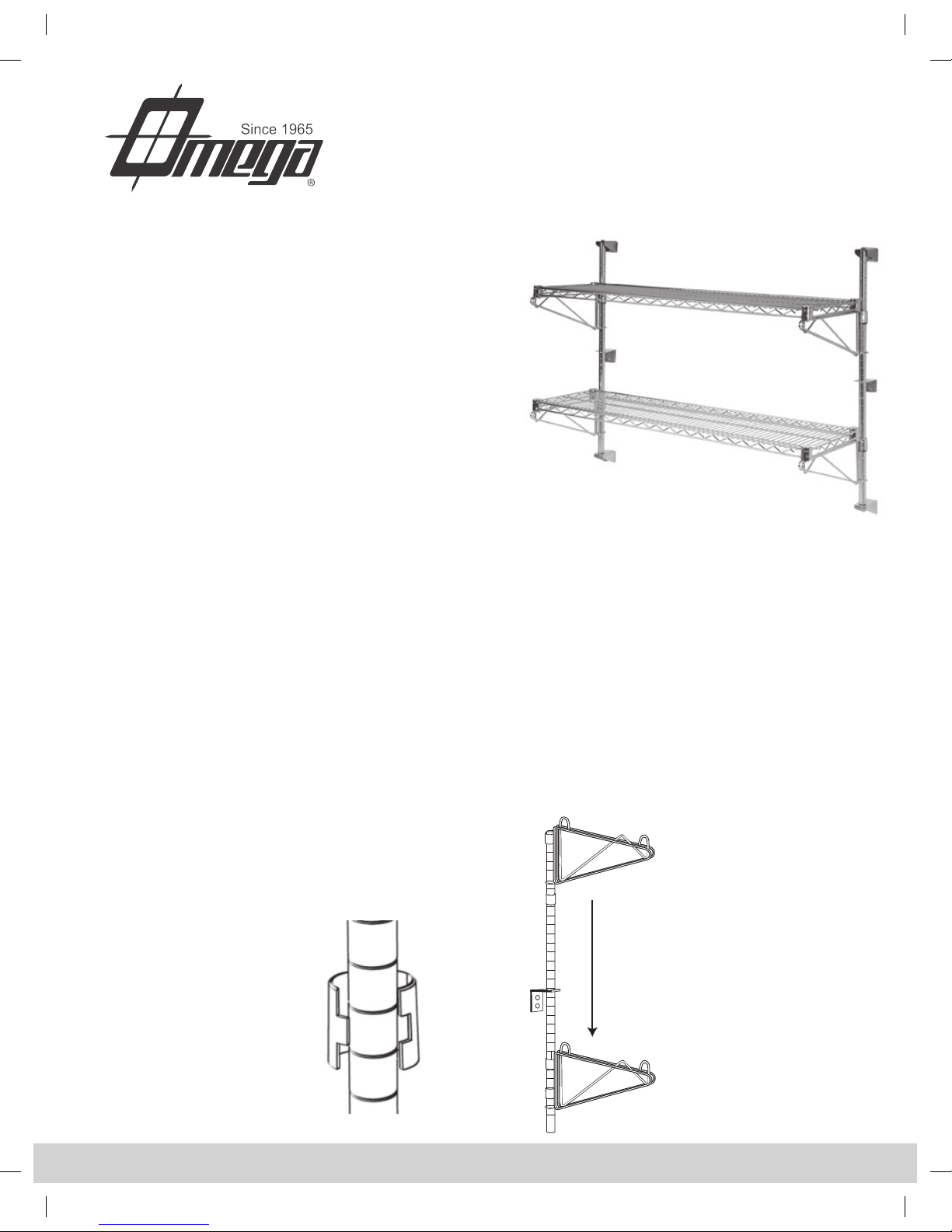
Cuente desde la parte inferior del poste y coloque las mangas de
plástico partidas (vea el Diagrama No. 1) sobre la muesca donde
desea ubicar el primer soporte escuadra fijado al poste.
Paso 6 Desde la parte de arriba del poste, deslice sobre las mangas
de plástico partidas el soporte escuadra que va fijado al poste.
(Vea el diagrama No. 2)
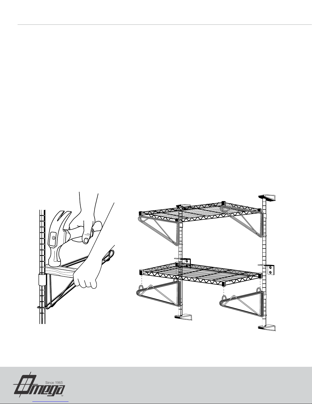
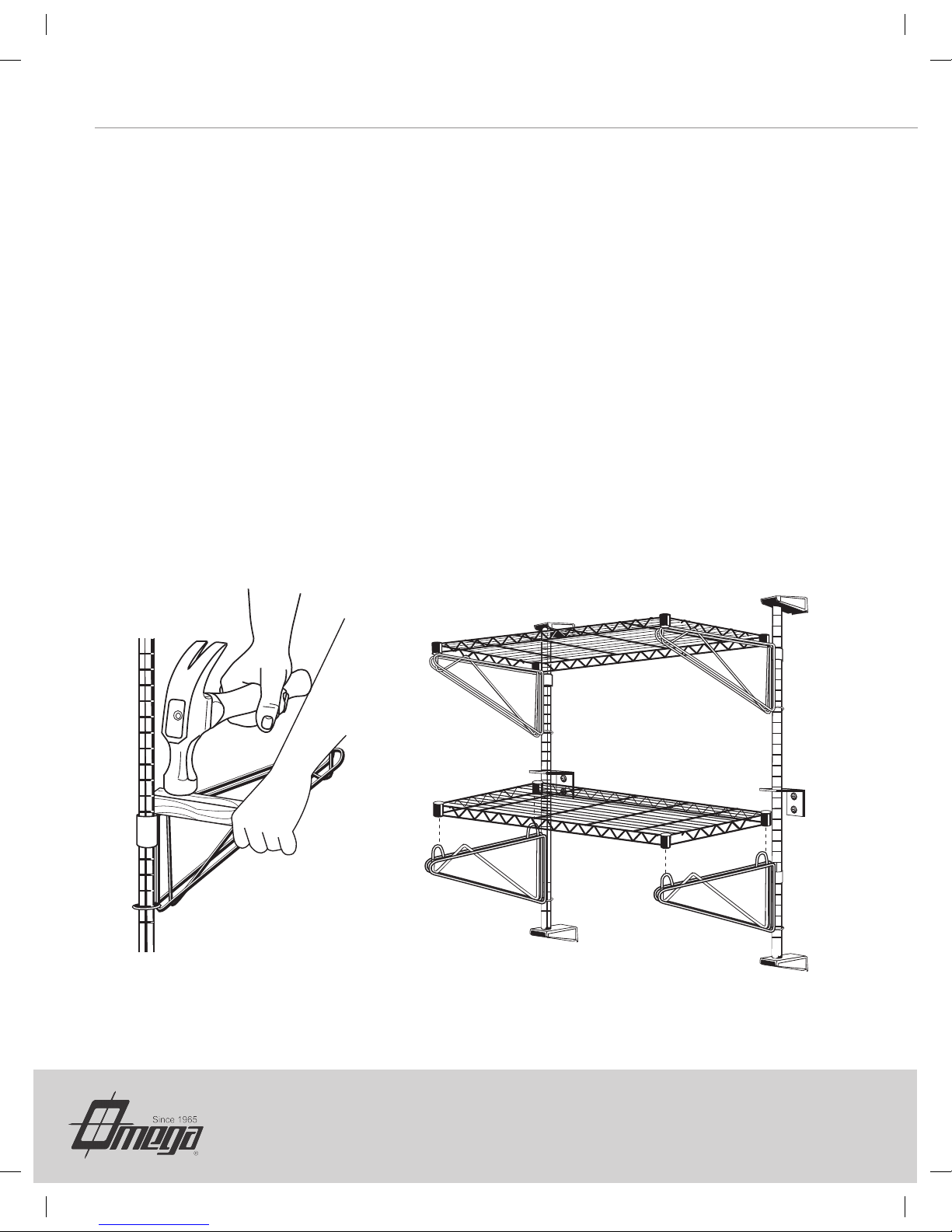
Paso 7 Si se está ensamblando una unidad de dos, tres o
cuatro hileras, deslice hacia abajo un soporte intermedio.
Paso 8 Para las unidades de 2, 3 o cuatro hileras repita los pasos
5, 6 y 7 hasta que todos los soportes hayan sido instalados.
Paso 9 Repita los pasos 4 al 8 para el/los poste(s) faltante(s)
DIAGRAMA 1
DIAGRAMA 2

INSTRUCCIONES DE MONTAJE
rev. 0309
DIAGRAMA 3 DIAGRAMA 4
Paso 10 Fije los soportes escuadra que van fijados al poste golpeándolos ligeramente con un mazo de goma
o utilizando un martillo y un bloque de madera. (Vea el Diagrama No. 3) Nunca utilice un martillo para
pegarle directamente al soporte sin usar un bloque de madera para proteger la unidad.
Paso 11 Monte un soporte extremo en cada punto donde hay un agujero de montaje. Asegúrese de que la pata
posterior de los soportes extremos dé hacia abajo. Apriete los tornillos solamente hasta quedar ajustados
sin holgura.
Paso 12 Tome un ensamble de poste y colóquelo entre los dos soportes extremos. A cada extremo del poste, pase
un perno (previamente retirado del poste) a través del soporte extremo y luego dentro del poste. Apriete
por completo los tornillos de montaje de los soportes extremos y los pernos de los postes.
Paso 13 Fije el/los soporte(s) intermedio(s) a cada uno de los correspondientes agujeros de montaje (si aplica,
dependiendo de la unidad que se está instalando).
Paso 14 Repita los pasos 12 y 13 para los demás ensambles de postes
Paso 15 Instale el/los anaquel(es) colocando los collares de esquina del/de los mismo(s) sobre los ojales de alambre
doblado de sujeción de los soportes escuadra que van fijados a los postes. (Vea el diagrama No. 4)
Paso 16 Inserte las tapas cromadas de los anaqueles en los collares de esquina del anaquel o los anaqueles.
ESTO COMPLETA EL MONTAJE DE LA UNIDAD
www.precisiontools.com
Call Customer Service at 1-800-221-8665 | Fax 631-563-5041
Table of contents
Languages:
Other Omega Storage manuals

Omega
Omega Security Cage with Aluminum Truck Dolly User manual

Omega
Omega Direct Mounted Wall Shelf User manual

Omega
Omega 46000 Instructions for use

Omega
Omega FFC18362CH User manual

Omega
Omega Security Module User manual

Omega
Omega HDS-Plus User manual

Omega
Omega Solid Stainless Steel Shelving User manual