ITALIANO ENGLISH
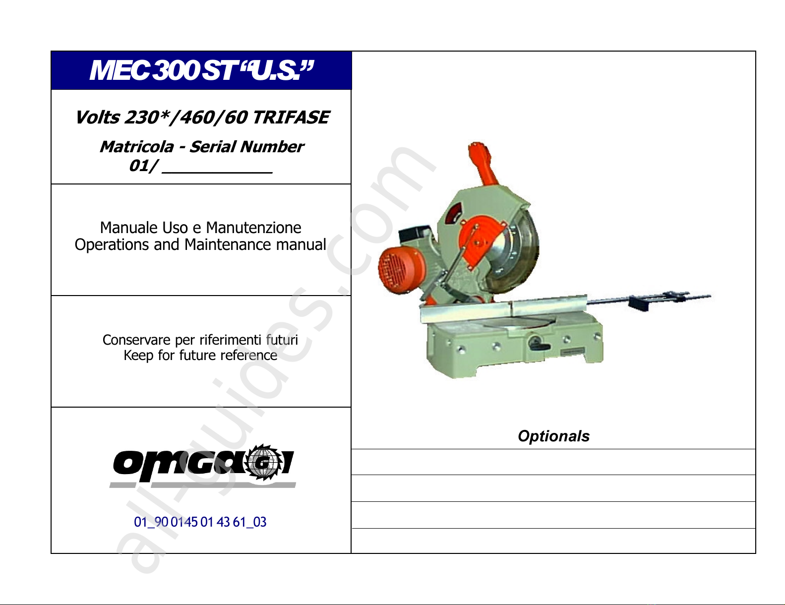
MEC 300 ST U.S. Volts 230*/460/60 TRIFASE01_90 0145 01 43 61_03
Pag. 4
INFORMAZIONI
GENERALI
GENERAL
INFORMATION
WARRANTY
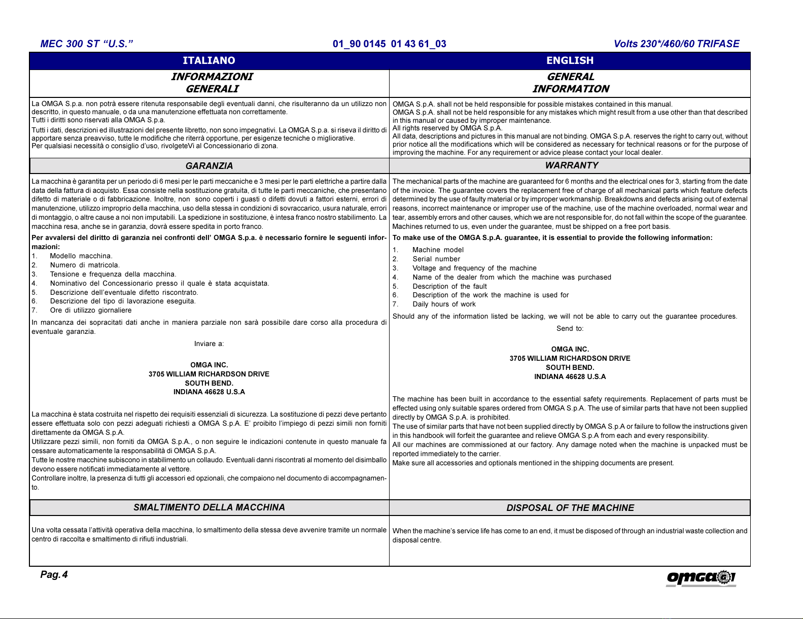
La OMGA S.p.a. non potrà essere ritenuta responsabile degli eventuali danni, che risulteranno da un utilizzo non
descritto, in questo manuale, o da una manutenzione effettuata non correttamente.
utti i diritti sono riservati alla OMGA S.p.a.
utti i dati, descrizioni ed illustrazioni del presente libretto, non sono impegnativi. La OMGA S.p.a. si riseva il diritto di
apportare senza preavviso, tutte le modifiche che riterrà opportune, per esigenze tecniche o migliorative.
Per qualsiasi necessità o consiglio duso, rivolgeteVi al Concessionario di zona.
OMGA S.p.A. shall not be held responsible for possible mistakes contained in this manual.
OMGA S.p.A. shall not be held responsible for any mistakes which might result from a use other than that described
in this manual or caused by improper maintenance.
All rights reserved by OMGA S.p.A.
All data, descriptions and pictures in this manual are not binding. OMGA S.p.A. reserves the right to carry out, without
prior notice all the modifications which will be considered as necessary for technical reasons or for the purpose of
improving the machine. For any requirement or advice please contact your local dealer.
GARANZIA
La macchina è garantita per un periodo di 6 mesi per le parti meccaniche e 3 mesi per le parti elettriche a partire dalla
data della fattura di acquisto. Essa consiste nella sostituzione gratuita, di tutte le parti meccaniche, che presentano
difetto di materiale o di fabbricazione. Inoltre, non sono coperti i guasti o difetti dovuti a fattori esterni, errori di
manutenzione, utilizzo improprio della macchina, uso della stessa in condizioni di sovraccarico, usura naturale, errori
di montaggio, o altre cause a noi non imputabili. La spedizione in sostituzione, è intesa franco nostro stabilimento. La
macchina resa, anche se in garanzia, dovrà essere spedita in porto franco.
Per avvalersi del diritto di garanzia nei confronti dell OMGA S.p.a. è necessario fornire le seguenti infor-
mazioni:
1. Modello macchina.
2. Numero di matricola.
3. ensione e frequenza della macchina.
4. Nominativo del Concessionario presso il quale è stata acquistata.
5. Descrizione delleventuale difetto riscontrato.
6. Descrizione del tipo di lavorazione eseguita.
7. Ore di utilizzo giornaliere
In mancanza dei sopracitati dati anche in maniera parziale non sarà possibile dare corso alla procedura di
eventuale garanzia.
Inviare a:
OMGA I C.
3705 WILLIAM RICHARDSO DRIVE
SOUTH BE D.
I DIA A 46628 U.S.A
La macchina è stata costruita nel rispetto dei requisiti essenziali di sicurezza. La sostituzione di pezzi deve pertanto
essere effettuata solo con pezzi adeguati richiesti a OMGA S.p.A. E proibito limpiego di pezzi simili non forniti
direttamente da OMGA S.p.A.
Utilizzare pezzi simili, non forniti da OMGA S.p.A., o non seguire le indicazioni contenute in questo manuale fa
cessare automaticamente la responsabilità di OMGA S.p.A.
utte le nostre macchine subiscono in stabilimento un collaudo. Eventuali danni riscontrati al momento del disimballo
devono essere notificati immediatamente al vettore.
Controllare inoltre, la presenza di tutti gli accessori ed opzionali, che compaiono nel documento di accompagnamen-
to.
he mechanical parts of the machine are guaranteed for 6 months and the electrical ones for 3, starting from the date
of the invoice. he guarantee covers the replacement free of charge of all mechanical parts which feature defects
determined by the use of faulty material or by improper workmanship. Breakdowns and defects arising out of external
reasons, incorrect maintenance or improper use of the machine, use of the machine overloaded, normal wear and
tear, assembly errors and other causes, which we are not responsible for, do not fall within the scope of the guarantee.
Machines returned to us, even under the guarantee, must be shipped on a free port basis.
To make use of the OMGA S.p.A. guarantee, it is essential to provide the following information:
1. Machine model
2. Serial number
3. Voltage and frequency of the machine
4. Name of the dealer from which the machine was purchased
5. Description of the fault
6. Description of the work the machine is used for
7. Daily hours of work
Should any of the information listed be lacking, we will not be able to carry out the guarantee procedures.
Send to:
OMGA I C.
3705 WILLIAM RICHARDSO DRIVE
SOUTH BE D.
I DIA A 46628 U.S.A
he machine has been built in accordance to the essential safety requirements. Replacement of parts must be
effected using only suitable spares ordered from OMGA S.p.A. he use of similar parts that have not been supplied
directly by OMGA S.p.A. is prohibited.
he use of similar parts that have not been supplied directly by OMGA S.p.A or failure to follow the instructions given
in this handbook will forfeit the guarantee and relieve OMGA S.p.A from each and every responsibility.
All our machines are commissioned at our factory. Any damage noted when the machine is unpacked must be
reported immediately to the carrier.
Make sure all accessories and optionals mentioned in the shipping documents are present.
SMALTIMENTO DELLA MACCHINA DISPOSAL OF THE MACHINE
Una volta cessata lattività operativa della macchina, lo smaltimento della stessa deve avvenire tramite un normale
centro di raccolta e smaltimento di rifiuti industriali.
When the machines service life has come to an end, it must be disposed of through an industrial waste collection and
disposal centre.