OMGA RN 450 FM "U.S" User manual

RN 450 FM “U.S”
Volts 230*/460/60 TRIFASE
Matricola - Serial Number
01/ ___________
01_90 0290 14 43 61_02
Optionals - Extras
Manuale Uso e Manutenzione
Operations and Maintenance manual
Conservare per riferimenti futuri
Keep for future reference


ITALIANO ENGLISH
Pag.3
Volts 230*/460/60 TRIFASE01_90 0290 14 43 61_02RN 450 FM “U.S.”
INDICE
Pag. Descrizione
CONTENTS
Pag. Contents
3 Indicegenerale.
4 Informazionigenerali.
4 Durataesmaltimentodellamacchina.
5 Leggereattentamente.
6 Vocabolariografico.
7 Imballaggio.
9 Assemblaggiodella macchina.
15 Montaggiodellalama.
17 Identificazionedellamacchina.
18 Descrizionedellamacchina.
20 Caratteristichetecniche.
21 Capacitàdi taglio.
23 Usodella macchina.
24 Rilevamentodel rumoreemesso.
25 Sollevamentoe spostamentodella macchina.
25 Predisposizioni.
26 Dimensioni.
27 Normedi sicurezza.
29 Marcaturadi sicurezza.
30 Dispositivi di sicurezza.
35 Collegamentoelettrico.
36 Impugnaturadi comando.
36 Arrestonormale
37 Regolazionealtezza braccio
38 Regolazioneangolazione delbraccio.
39 Regolazione inclinazione lama.
41 Utilizzo della macchina
45 Operazionedi manutenzione.
47 Sostituzione della lama.
49 Controlli di assetto.
56 Schemaelettrico.
58 Parti di ricambio.
3 Contents.
4 Generalinformation.
4 Servicelife and disposal of themachine.
5 Readcarefully.
6 Key to the graphic symbols.
7 Packaging.
9 Machineassembly.
15 Assembly of the blade.
17 Machineidentification.
18 Descriptionof the machine.
20 Technicalspecifications.
21 Cutting capacity.
23 Operatingthe machine.
24 Noiseemission measurements.
25 Liftingand shifting the machine.
25 Positioningrequrements.
26 Overalldimensions.
27 Safty rules.
29 Saftymarking.
30 Saftydevices.
35 Electrical connections.
36 Controlhandgrip.
36 Normalstopping
37 Adjusting the height of the arm.
38 Adjusting the angle of the arm.
39 Adjustingthe inclinaion of the blade
41 Usingthe machine.
45 Operationthe maintenance.
47 Replacingthe blade.
49 Set-Up checks.
56 Electricalwiring diagrams.
58 Spareparts.

ITALIANO ENGLISH
RN 450 FM “U.S.” Volts 230*/460/60 TRIFASE01_90 0290 14 43 61_02
Pag.4
INFORMAZIONI GENERALI GENERAL INFORMATION
La OMGA S.p.A. non potrà essere ritenuta responsabile degli eventuali danni, che risulteranno da un
utilizzo non descritto, in questo manuale, o da una manutenzione effettuata non correttamente.
Tutti i diritti sono riservati alla OMGA S.p.A.
Tutti i dati, descrizioni ed illustrazioni del presente libretto, non sono impegnativi. La OMGA S.p.A. si
riserva il diritto di apportare senza preavviso, tutte le modifiche che riterrà opportune, per esigenze
tecniche o migliorative.
Per qualsiasi necessità o consiglio d’uso, rivolgeteVi al Concessionario di zona.
GARANZIA
WARRANTY
OMGA S.p.A. shall not be held responsible for possible mistakes contained in this manual.
OMGA S.p.A. shall not be held responsible for any mistakes which might result from a use other than
that described in this manual or caused by improper maintenance.
All rights reserved by OMGA S.p.A.
All data, descriptions and pictures in this manual are not binding. OMGA S.p.A. reserves the right to
carry out, without prior notice all the modifications which will be considered as necessary for
technical reasons or for the purpose of improving the machine. For any requirement or advice please
La macchina è garantita per un periodo di 6 mesi per le parti meccaniche e 3 mesi per le parti elettriche
a partire dalla data della fattura di acquisto. Essa consiste nella sostituzione gratuita, di tutte le parti
meccaniche, che presentano difetto di materiale o di fabbricazione. Inoltre, non sono coperti i guasti
o difetti dovuti a fattori esterni, errori di manutenzione, utilizzo improprio della macchina, uso della
stessa in condizioni di sovraccarico, usura naturale, errori di montaggio, o altre cause a noi non
imputabili. La spedizione in sostituzione, è intesa franco nostro stabilimento. La macchina resa, anche
se in garanzia, dovrà essere spedita in porto franco.
Per avvalersi del diritto di garanzia nei confronti della OMGA S.p.A. è necessario fornire
le seguenti informazioni:
1. Modello macchina.
2. Numero di matricola.
3. Tensione e frequenza della macchina.
4. Nominativo del Concessionario presso il quale è stata acquistata.
5. Descrizione dell’eventuale difetto riscontrato.
6. Descrizione del tipo di lavorazione eseguita.
7. Ore di utilizzo giornaliere
In mancanza dei sopracitati dati anche in maniera parziale non sarà possibile dare corso alla proce-
dura di eventuale garanzia. Inviare a:
OMGAINC.
3705WILLIAMRICHARDSONDRIVE
SOUTHBEND.
INDIANA46628 U.S.A
E-mail:[email protected]
Web: www.omgainc.com
La macchina è stata costruita nel rispetto dei requisiti essenziali di sicurezza. La sostituzione di pezzi
deve pertanto essere effettuata solo con pezzi adeguati richiesti a OMGA Inc. E’ proibito l’impiego di
pezzi simili non forniti direttamente da OMGA Inc.
Utilizzare pezzi simili, non forniti da OMGA Inc. o non seguire le indicazioni contenute in questo
manuale fa cessare automaticamente la responsabilità di OMGA S.p.A.
Tutte le nostre macchine subiscono in stabilimento un collaudo. Eventuali danni riscontrati al momento
del disimballo devono essere notificati immediatamente al vettore.
Controllare inoltre, la presenza di tutti gli accessori ed opzionali, che compaiono nel documento di
accompagnamento.
The mechanical parts of the machine are guaranteed for 6 months and the electrical ones for 3,
starting from the date of the invoice. The guarantee covers the replacement free of charge of all
mechanical parts which feature defects determined by the use of faulty material or by improper
workmanship. Breakdowns and defects arising out of external reasons, incorrect maintenance or
improper use of the machine, use of the machine overloaded, normal wear and tear, assembly errors
and other causes, which we are not responsible for, do not fall within the scope of the guarantee.
Machines returned to us, even under the guarantee, must be shipped on a free port basis.
To make use of the OMGA S.p.A. guarantee, it is essential to provide the following information:
1. Machine model
2. Serial number
3. Voltage and frequency of the machine
4. Name of the dealer from which the machine was purchased
5. Description of the fault
6. Description of the work the machine is used for
7. Daily hours of work
Should any of the information listed be lacking, we will not be able to carry out the guarantee
procedures.
Send to:
OMGAINC.
3705WILLIAMRICHARDSONDRIVE
SOUTHBEND.
INDIANA46628 U.S.A
E-mail:[email protected]
Web: www.omgainc.com
The machine has been built in accordance to the essential safety requirements. Replacement of parts
must be effected using only suitable spares ordered from OMGA Inc. The use of similar parts that
have not been supplied directly by OMGA Inc. is prohibited.
The use of similar parts that have not been supplied directly by OMGA Inc. or failure to follow the
instructions given in this handbook will forfeit the guarantee and relieve OMGA S.p.A from each and
every responsibility.
SMALTIMENTO DELLA MACCHINA
Una volta cessata l’attività operativa della macchina, lo smaltimento della stessa deve
avvenire tramite un normale centro di raccolta e smaltimento di rifiuti industriali.
DISPOSAL OF THE MACHINE
When the machine’s service life has come to an end, it must be disposed of through
an industrial waste collection and disposal centre.

ITALIANO ENGLISH
Pag.5
Volts 230*/460/60 TRIFASE01_90 0290 14 43 61_02RN 450 FM “U.S.”
LEGGERE ATTENTAMENTE READ CAREFULLY
Lasicurezzapresuppone l’osservanzadelle normeantinfortunistichevigenti in ogni
Paesedel mondo.
L’Utilizzatore si farà carico dell’istruzione del personale che opererà con questa
macchina.
Prima di ogni collegamento a qualsiasi fonte di energia elettrica e pneumatica e
prima di attivare la macchina, l’Operatore dovrà leggere attentamente le nor-
me descritte in questo manuale .
All’internodi questomanuale, in ognicapitolo chedescriva modalitàdi operareo di
manutenzioneche comportinoanche unaminima possibilitàdi rischio,sono inseriti
simboligrafici cherichiamano l’attenzionedell’Operatore.
Ognisimbolo graficoè chiaramente commentato a pagina6nel “VOCABOLARIO
GRAFICO”.
Forsafety purposesit is necessary to observe the accident-preventionstandards in
forcein the country where the machine is operated.
The user is responsible for training the personnel who are to use this machine.
Beforeconnecting to any electrical or pneumatic energy sourceand before starting
the machine, the operator must read carefully the rules described in this
manual.
All chapters in this manual which describe operating or maintenance procedures
involvingeventheslightestriskcontaingraphicsymbolstodrawtheoperator’sattention
to the risk.
Themeaningsof thegraphicsymbols areexplainedclearly onpages6in the section
“KEYTO GRAPHIC SYMBOLS“.

ITALIANO ENGLISH
RN 450 FM “U.S.” Volts 230*/460/60 TRIFASE01_90 0290 14 43 61_02
Pag.6
Vocabolario
grafico Key
to graphic
Attenzione generico Generic danger
Attenzione al collegamento all’impian-
to di aspirazione Pay attention to dust extraction
system connection
Indossare grembiule protettivo di
cuoio Protective leather apron must be
worn
Dotarsi di mezzi di estinzione di
incendio Fire-fighting equipment must be
readily available
Dotarsi di cassetta di pronto soccor-
so
Assunzione di informazioni
First-aid kit must be readily available
Information
Vocabolario
grafico Key
to graphic
ITALIANO ENGHISH
Symbol
Divieto di procedere senza aver
letto il paragrafo precedente It is forbidden to proceed without
reading the corresponding section
Operazioni vietate Prohibited operations
Obbligo di indossare occhiali di
protezione Safety glasses must be
worn
Obbligo di indossare guanti di
protezione Protective gloves must be
worn
Obbligo di indossare calzature
idonee Suitable footwear must be
worn
Obbligo di indossare cuffie di
protezione dal rumore Ear defenders must be
worn
Pericolo generico Generic danger
Pericolo di scarica elettrica e/o
presenza di tensione Danger of electrical
discharge and/or presence of
live parts
Attenzione al collegamento
elettrico Pay attention to the
electrical connection
Attenzione al collegamento
pneumatico Pay attention to the
pneumatic connection
Symbol ENGHISHITALIANO

ITALIANO ENGLISH
Pag.7
Volts 230*/460/60 TRIFASE01_90 0290 14 43 61_02RN 450 FM “U.S.”
IMBALLAGGIO PACKAGING
L’imballaggio è costituito da un cartone rigido di dimensioni CM 106 x 41 con un’altezza
di 76 Fig. 1. Il cartone deve presentarsi chiuso dalle apposite graffette, integro e senza
ammaccature derivanti dal trasporto o da manomissione di terzi. La macchina all’inter-
no del cartone è smontata in varie parti. Ogni parte è imballata con nylon o in cartone.
Accertarsi durante il disimballo che non vi siano nylon strappati o cartoni danneggiati.
Per eseguire il corretto disimballo seguire le seguenti istruzioni:
1. Aprire superiormente il cartone ed assicurarsi che l’interno si
presenti come inFig.2.Rimuovere i vari spessori in polistirolo e cartone (1) e la
busta contenente il manuale uso e manutenzione (2).
2. Sfilare dal cartone il tavolo da (3);il banco di appoggio (4)e il cartone contenente i 4
piedi (5). Fig. 3.
3. Tramite un paranco di adeguata portata, sollevare il braccio portante (6) della
macchina. Controllare che sotto al braccio ci sia imballata la sponda di appoggio
e il controtavolo (7). Fig. 4.
4. Rimuovere dall’imballo la confezione contenente il gruppo operante (8) Fig. 4.
5. All’interno della confezione contenente il gruppo operante si troveranno le seguen-
ti parti: Fig. 5 e 6.
a) Gruppo operante.
b) Testata anteriore.
c) Protezione regolabile e bocca di aspirazione.
d) Carter coprilama.
e) Busta chiavi di dotazione.
f) Molla di ritorno automatico.
6. Controllare che all’interno della confezione (e) vi siano i seguenti pezzi:
· Antenna portacavo.
· Rondella comune tranciata 8x24x2.
· Vite Testa esagonale 8x16.
· Chiave fissa CH 27/32.
· Chiave fissa CH 17/19.
· Chiave fissa CH 10.
· Cacciavite.
· Chiave a tubo 17 più asta.
· Chiave a tubo 13.
· Chiavi Allen 4/5/6/8 speciale.
· 10 viti 10 x 25.
· 10 rondelle ø 10mm.
· 2 dadi zincati.
· Lamina 0,2 mm.
Eventuali reclami per la mancanza dei materiali sopra descritti, vengono accettati solose:
1. Segnalati immediatamente entro 7 giorni dal disimballo della macchina.
2. Solo se accompagnati da fotocopia del talloncino riportante il numero del nostro
operatore che ha curato l’imballo stesso. Detto talloncino è applicato sulla busta
dove era contenuto il manuale uso e manutenzione.
Packaging is made up by a heavy duty cardboard measuring 106 x 41 centimeters and 76
centimeters of high (see Fig. 1.) The cardboard box should be sealed from the factory
with the appropriate staples in good conditions and without dents caused by miss handling.
The machine inside is made up by several disassembled components. Each component
is protected by plastic bags and card board. It is very important to make sure during the
unpacking that plastic bags and protective cardboard are tear free. To unpack the machine
in the correct manner proceed as follows:
1. Open the top lid to the cardboard box and make sure the content is as per Fig. 2.
Remove the Styrofoam and cardboard supports (1) and the envelope containing the
instruction manual (2).
2. From the box, pull up the wooden table (3) , the metal frame (4) and the compartment
box containing the 4 legs (5). See Fig. 3.
3. Using an appropriately sized jack, lift the arm (6) of the machine. Verify that the wooden
fence and the counter-table are wrapped inside the arm (7). See Fig. 4.
4. Remove the operating unit (8) from its own box. See Fig. 4
5. Inside the box containing the operating unit you will find the following components:
see Fig 5 and 6
a) Operating Unit
b) Plastic end cover for arm
c) Ripping guard with dust chute (not on all model)
d) Blade guard
e) Spanner set
f) Automatic head return device
6. Verify that package (e) contains the following:
· Wire holder
· 8x24x2 mm washer
· 8x6 mm bolt
· CH 27/32 wrench
· CH 17/19 wrench
· CH 10 wrench
· Screw driver
· 17mm closed end wrench with pulling rod
· 13mm closed end wrench
· 4/5/6/8 special Allen wrench
· Quantity of 10. 10x25mm screws
· Quantity of 10, 10mm washers
· Quantity of 2 nuts
· 0.2mm shim
Any complaints concerning missing material will only be accepted if:
1. Notified within 7 days from unpacking the machine;.
2. Accompanied by a photocopy of the slip bearing the number of our operator in charge
of packaging. You will find this slip on the envelope containing the use and mainte-
nance manual.

Pag.8
Volts 230*/460/60 TRIFASE
01_90 0290 14 43 61_02
RN 450 FM “U.S.”
ITALIANO ENGLISH
IMBALLAGGIO PACKAGING
A
H
B
abc
ef
ABH
106 41 76
CM 5
4
3
1
2
7
Fig. 1 Fig. 2 Fig. 3
Fig. 4 Fig. 5 Fig. 6
6
8
d

ITALIANO ENGLISH
RN 450 FM “U.S.” Volts 230*/460/60 TRIFASE
01_90 0290 14 43 61_02
Pag.9
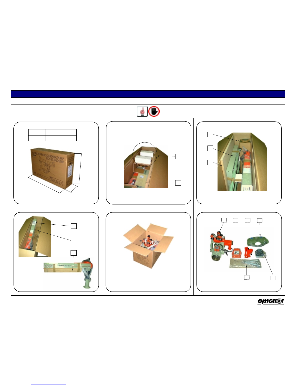
After you have unpacked the machine; assemble it in accordance to the following instructions:
ATTENTION: do not assemble the machine if any of the items described in the previous chapter
are missing.
1. Take the four feet out of their pack.
2. Place the work bench on the floor and tip it on its side (Fig. 1).
3. Secure the four feet to the bench, using two galvanised 10x25 screws and two diameter 10
washers (2) for each foot. For this operation use the CH 17 wrench (1) supplied. After this
operation, the bench must have the appearance illustrated in Fig. 1.
4. Tip the bench back up, so that it rests on its four feet (Fig. 2).
5. Unpack the third side guide (3) fastened to the bench. Unscrew the two nuts from their stud bolts
and fit the guide onto them. Fig. 2.
6. Unpack the arm and remove the fence and counter table from the wrap.The supporting arm of the
machine and the colum are fixed to the bottom of the cage by means of two screws and the re-
levant locknuts (4). Fig. 3 Unscrew them with the CH 17 wrench.
7. Using a hoist with a suitable load bearing capacity, lift the support arm and, using a hammer, tap
the two heads of the pins (5) until their top part is level with the column support. Fig. 3.
8. Couple the column support with the supporting base of the bench by fitting the two pins (5) into
the seats provided for this purpose (6). Fig. 4.
9. Wrench the 10x30 mm screws down with their diameter 10 mm washers, using a CH 17 wrench.
Fig. 4.
10. After these operations, the machine must have the appearance illustrated in Fig. 5.
11. Using the size 13 socket wrench, remove the 6 nuts and relevant washers from the guides of the
table. Remove the 3 remaining screws and washers with the screwdriver. Fig. 5.
12. Assemble the wooden table by letting the bolts mounted on the rail, through the correspondent
holes on the table see Fig. 6. WARNING: The wooden table (7) must be positioned with the
two rounded corners facing the operator opposite the column support. Fig. 7.
13. Using the size 13 socket wrench (8) refit the 6 nuts and washers previously removed
(identified by the arrows) Fig. 7.
14. Using the screwdriver (9) refit the remaining 3 screws and washers Fig. 8.
15. Unpack the fence in order to obtain the two pieces that compose it: the fence and the countertable.
Assemble the fence (10) and the countertable (11) by placing them up against the work bench,
as shown in Fig. 9. Secure them to the bench by tightening the two knobs (12).
16. Fit the cutting unit into the guides located inside the supporting arm. When you are carrying out
this operation, pay particular attention to dust scraper. An incorrect position can damage this
part and render it ineffective. Fig. 10.
17. Open up the pack (b) and fit the arm release lever (13). Fit the tie-rod (14) into its hole. Fig. 11.
18. Mount the front head (15) by securing it to the support arm by means of the two screws you
have found in the pack and the 4 mm Allen wrench (16) Fig. 12.
Dopo aver provveduto a disimballare la macchina, si dovrà procedere all’assemblaggio della stesa:
ATTENZIONE: Non procedere all’assemblaggio, se la macchina manca anche solo di una parte
descritta nel capitolo precedente.
1. Estrarre i 4 piedi di sostegno dalla propria confezione.
2. Prendere il banco di appoggio e posizionarlo di lato a terra. Fig. 1.
3. Fissare i 4 piedi al banco, ognuno dei quali necessita di 2 viti 10x25 zincate e 2 rondelle ø10 (2),
Per fare questa operazione utilizzare la chiave CH 17 (1) in dotazione. Al termine il banco di
appoggio si deve presentare come in Fig. 1.
4. Sollevare il banco e metterlo parallelo al terreno. Fig. 2.
5. Disimballare la terza guida laterale (3) agganciata al banco. Svitare i 2 dadi dai prigionieri e infilare
su di essi la guida. Fig. 2.
6. Disimballare il braccio portante e staccare la sponda di appoggio e il controtavolo legata sotto di
esso, il braccio portante della macchina e la colonna sono agganciati al fondo della gabbia tramite
due viti con relativi controdadi (4). Fig. 3. Svitarli con chiave CH 17.
7. Tramite un paranco di adeguata portata sollevare il braccio portante e con un martello battere le
teste delle due spine (5) finché la loro parte superiore non sarà a filo del supporto colonna. Fig.
3.
8. Accoppiare il supporto colonna con la base di appoggio sul banco in modo che le due spine (5)
vadano all’interno delle sedi (6) predisposte. Fig. 4.
9. Avvitare a fondo le quattro viti 10x30 mm con le relative rondelle ø 10 mm utilizzando una chiave
CH 17. Fig. 4.
10. Alla fine di queste operazioni la macchina si deve presentare come in Fig. 5.
11. Tramite la chiave a tubo da 13, smontare i 6 dadi presenti sulle guide del tavolo e le relative
rondelle. Smontare le rimanenti 3 viti e le rondelle con il cacciavite a stella. Fig. 5.
12. Prendere il piano di lavoro e montarlo, infilando i prigionieri sporgenti dalle guide, negli appositi fori
Fig. 6. ATTENZIONE: Posizionare il tavolo di lavoro (7) con gli angoli smussati verso l’esterno
rispetto al supporto colonna. Fig. 7.
13. Tramite la chiave a tubo da 13 (8) rimontare avvitando a fondo i 6 dadi e le rondelle precedente-
mente smontati (raffigurati con le frecce) Fig. 7.
14. Tramite il cacciavite a stella (9) rimontare le rimanenti 3 viti e rondelle Fig. 8.
15. Disimballare la sponda di appoggio in modo da avere i due pezzi che la compongono: la sponda
e il controtavolo. Montare la sponda di appoggio (10) e il controtavolo (11) appoggiandoli a
contatto del tavolo di lavoro come mostrato in Fig. 9. Fissarli al tavolo tramite la chiusura dei due
pomelli (12).
16. Inserire il gruppo operante nelle guide situate all’interno delle braccio portante. Nell’eseguire
questa operazione fare molta attenzione alla posizione dei raschia polveri. Una posizione
sbagliata può rovinare tale elemento rendendolo inefficace. Fig. 10.
17. Aprire la confezione (b) e procedere al montaggio della leva di sbloccaggio braccio (13). Inserire
il tirante (14) nel foro appositamente predisposto. Fig. 11.
18. Montare la testata anteriore (15) fissandola al braccio portante per mezzo delle due viti trovate
nella confezione utilizzando la chiave Allen 4 mm. (16) Fig. 12.
ASSEMBLAGGIO DELLA MACCHINA MACHINE ASSEMBLY

ITALIANO ENGLISH
RN 450 FM “U.S.” Volts 230*/460/60 TRIFASE01_90 0290 14 43 61_02
Pag.10
ASSEMBLAGGIO DELLA MACCHINA MACHINE ASSEMBLY
19.Smontare le viti (17) poste sul banco di sostegno. Aprire il coperchio del
salvamotoresvitando leviti (18).Fig. 13.
20.Posizionare il salvamotore sul banco di sostegno come raffigurato in Fig. 14 e
fissarlodall’interno con le 2 viti(17)nei punti (19). Richiudere ilsalvamotore.
21.Montare l’antenna portacavo (20) sul braccio portante tramite una vite 8x16 ed
unarondella. Avvitare iltutto con una chiave CH 17. Fig. 15.
22.Aprire laconfezione della molla di ritorno(e). Smontare i due dadidi bloccaggio
(21)inmodo dadividere ilsupporto molladalla molla stessa. Avvitare ilsupporto
molla(22)al braccio portante per mezzo delledue viti 6x16mm e diuna chiave
Allen 4 mm (23). Fig. 16.
23.La molla di ritorno si deve presentare come in Fig. 17, con le due viti 6x40 a sx
(24), 6x50 a dx(25) montate,e il distanziale molla (26)infilato negliappositi fori.
Procedere al montaggio della molla sul supporto molla per mezzo delle due viti
(24) e (25) e dei due dadi (21). Montare il tutto con una chiave Allen 4 mm (27)
euna CH 10(28).Avvitare a fondo. Fig. 17 e18.
24.Portare il gruppo operante in posizione di riposo (gruppo a fine corsa verso la
colonnaportante) e collegare l’occhiello terminaledella molladi ritornoal gancio
predisposto(29) sul gruppooperante. Fig. 18.
25.Prendere il carter coprilama (30). Fig. 19.
26.Asportare tramite una chiave atubo da17 (31),ildado ela rondella(32).Fig. 20.
27.Inserire il carter coprilama sul perno di supporto (33) come in Fig. 21.
28.Rimontare la rondella e il dado e fissare il tuttocon chiave atubo da 17.Fig. 21.
29.Al termine delle operazioni sopradescritte lamacchina sideve presentarecome
in Fig. 22.
30.Si raccomanda di mettere subito in bolla la macchina. Per far ciò in dotazione
sonodate 2viti 10x25e 2dadi damontare suuno odue piedi.Qualora sidoves-
se ricorrere a tale regolazione, montare le viti e i dadi come in Fig. 23.
19. Remove the screws (17) from the table support. Open the lid to the
transformer box by loosening the plastic screws (18) see Fig. 13.
20. Position the thermal overload on the frame of the machine as seen in Fig. 14
and secure it from the inside with the 2 screws (17) through the holes (19).
Closethe lid to the thermal overload box.
21. Mount the cable carrying rod (20)onto the supportingarm by means of a8x16
screw and a washer. Screw down using a CH 17 wrench. Fig. 15.
22. Open up the reversal spring package (e). Remove the two fixing nuts (21) in
orderto divide thespring from its mount. Screw the spring mount (22) onto the
arm by means of the two 6x16 mm screws and a 4 mm Allen wrench (23). Fig.
16.
23. The reversal spring must have the appearance of the illustration in Fig. 17 i.e.
withthe two 6x40screws fittedon the left(24), the 6x50on theright (25)andthe
springspacer (26)inserted into the right holes.Mount thespring ontoits mount
by means of the two screws (24 and 25) and the two nuts (21). Tighten them
down with a 4 mm Allen wrench (27) and a CH 10 (28). Wrench hard. Fig. 17
and18.
24. Move the cutting unit to idle position (the unit must be moved to the end of its
stroke towards the column) and connect the last coil of the reversal spring to
the appropriate hook (29) on the cutting unit. Fig. 19.
25. Take the blade guard (30).See Fig. 19.
26. Remove the nut and washer (31) with a size 17 socket wrench (32), Fig. 20.
27. Insert the the blade casing into its support pin (33) as shown in Fig. 21.
28. Refit the nut and washer and tighten down with a size 17 socket wrench. Fig.
21.
29. After these operations,the machine musthave the appearanceof Fig. 22.
30. Youcannow leveloffthe machine. Forthis operation,you are providedwith two
10x25screws and 2nuts to fitonto one ortwo feet. Ifadjustments are needed,
fit the nuts and screws as shown in Fig. 23.

Pag.11
Volts 230*/460/60 TRIFASE
01_90 0290 14 43 61_02
RN 450 FM “U.S.”
ITALIANO ENGLISH
Fig. 1 Fig. 2 Fig. 3
Fig. 4 Fig. 5 Fig. 6
1
2
34
4
5
6
ASSEMBLAGGIO DELLA MACCHINA MACHINE ASSEMBLY

ITALIANO ENGLISH
RN 450 FM “U.S.” Volts 230*/460/60 TRIFASE01_90 0290 14 43 61_02
Pag.12
7
Fig. 7
Fig. 10
Fig. 8
Fig. 11 Fig. 12
Fig. 9
ASSEMBLAGGIO DELLA MACCHINA MACHINE ASSEMBLY
8
9
10 11
12
14
13
15
16

ITALIANO ENGLISH
Pag.13
Volts 230*/460/60 TRIFASE01_90 0290 14 43 61_02RN 450 FM “U.S.”
28
Fig. 15
Fig. 13
Fig. 16
Fig. 14
Fig. 17
ASSEMBLAGGIO DELLA MACCHINA MACHINE ASSEMBLY
18
17
19
20
21 22 23
24
26
25
27
25
24

Pag.14
Volts 230*/460/60 TRIFASE
01_90 0290 14 43 61_02
RN 450 FM “U.S.”
ITALIANO ENGLISH
ASSEMBLAGGIO DELLA MACCHINA MACHINE ASSEMBLY
Fig. 18
Fig. 21
Fig. 19
Fig. 22
Fig. 20
Fig. 23
27
28
30
32
29
31
33

ITALIANO ENGLISH
RN 450 FM “U.S.” Volts 230*/460/60 TRIFASE
01_90 0290 14 43 61_02
Pag.15
MONTAGGIO DELLA LAMA ASSEMBLY OF THE BLADE
Per eseguire il corretto montaggio della lama procedere come descritto di seguito:
1. Rimuovere l’anello benzing (1) tramite il cacciavite, in modo da separare le 2 prote-
zioni laterali dx Fig. 1.
2. Con chiave a tubo CH 17 asportare il dado di bloccaggio e la rondella che tengono
fissato il carter coprilama al motore. Fig. 2. Asportare il carter coprilama.
3. Con chiave CH 32 (2) e Allen 8 mm (3), smontare il dado di serraggio, il distanziale e
la flangia esterna. Fig. 3/4.
4. Inserire la lama sul mandrino. Inserire la flangia esterna ed il dado di serraggio.
ATTENZIONE: La faccia del dado di serraggio a contatto con la flangia esterna deve
essere sempre la stessa. Ribloccare a fondo il tutto. Fig. 5.
L’utensile utilizzato deve avere la caratteristiche descritte a pagina 20. Si raccomanda
l’utilizzo di guanti di protezione durante l’esecuzione dell’operazione di montaggio lama.
Accertarsi del corretto inserimento, relativamente al senso di rotazione, come indicato
dalla freccia presente sul carter coprilama.
ATTENZIONE: Prima di eseguire il montaggio della flangia esterna verificare l’assoluta
pulizia della stessa. Verificare l’assenza di grasso oppure di lubrificante tra la lama e le
due flange di bloccaggio.
5. Rimontare il carter coprilama sul perno di sostegno.
6. Rimontare la rondella e con chiave a tubo CH 17 rimontare il dado di bloccaggio del
carter coprilama. Bloccare il tutto a fondo. Fig.5
7. Riagganciare le 2 protezioni laterali dx tramite il relativo perno e l’anello benzing. Fig.
6.
Tocorrectlyassemble theblade:
1. RemovetheBenzing ring (1)by meansofthe screwdriver,inorder toseparatethe 2
righthandguards,Fig. 1.
2. UsingaCH17socketwrenchremovethenutandwasherthatsecurethebladecasing
tothemotor. Fig.2. Removethe bladecasing.
3. UsingaCH 32 wrench(2)and an8mm Allen wrench (3),remove the fixingnut,the
spacerandouterflange.Fig.3/4.
4. Fit the blade onto the chuck. Fit the outer flange and fixing nut. ATTENTION: the
surfaceofthenut cominginto contactwith theouterflangemustalwaysbethesame.
Wrenchdown.Fig.5.
Thetoolusedmusthavethefeaturesdescribedon page20. Theuse ofprotective gloves
duringthebladefittingoperationsishighly recommended.Make surethebladehasbeen
correctlyfittedandthatitruns inthe rightdirection,asindicatedbythearrowonthe blade
casing.
IMPORTANT: before fittingtheouter flange, makesureit is perfectlyclean.Make sure
thereare notracesofgreaseor lubricantbetweenthe bladeandthefixingflanges.
5. Refittheblade casingintothe pin.
6. Refitthewasher and, with a CH 17 socketwrench,refittheblade casing fixing nut.
Wrenchdown.Fig.5
7. Refitthe2 righthand sideguardswith thepinand theBenzingring. Fig.6.

Pag.16
Volts 230*/460/60 TRIFASE
01_90 0290 14 43 61_02
RN 450 FM “U.S.”
ITALIANO ENGLISH
MONTAGGIO DELLA LAMA ASSEMBLY OF THE BLADE
Fig. 3
Fig. 2
Fig. 4 Fig. 5 Fig. 6
Fig. 1 1
2
3

ITALIANO ENGLISH
RN 450 FM “U.S.” Volts 230*/460/60 TRIFASE
01_90 0290 14 43 61_02
Pag.17
IDENTIFICAZIONE DELLA MACHINAMACHINE IDENTIFICATION
12
RN 450 FM U.S.
01- 2001
60 2,9 9230
12”
11”3/4
1”
1000
L’identificazionenominativa dellamacchina è possibiletramite latarghetta (1). Sulla
targhetta(2) appaiono i seguenti dati:
1. Indirizzodel costruttore.
2. Modellodella macchina.
3. Numerodi matricola.
4. Anno di costruzione.
5. Frequenzain Hertz.
6. Potenza totale installata in kWatt.
7. Assorbimentoin Ampere.
8. Voltaggio in Volt.
9. Diametro massimo della lama in pollici.
10.Diametrodel foro in pollici.
11.Diametro minimo della lama in pollici.
12.Peso complessivo della macchina in N.
Thenameofthemachinecanbereadontheprintedplate(1).Thefollowinginformation
isgiven on thefront name plate(2):
1. Addressof themanufacturer.
2. Machinemodel.
3. Serialnumber.
4. Year ofmanufacture.
5. Frequencyin Hertz.
6. Total power installed in kW.
7. Currentdraw inAmperes.
8. Voltage in Volts.
9. Maximum diameter of the blade in inch.
10.Diameter of the blade hole in inch.
11.Minimum diameter of the blade in inch.
12.Overallweight of the machine inN.

ITALIANO ENGLISH
RN 450 FM “U.S.” Volts 230*/460/60 TRIFASE01_90 0290 14 43 61_02
Pag.18
2 3 4 5 6
1
7813
910 12
11
DESCRIZIONE DELLA MACCHINA DESCRIPTION OF THE MACHINE
14 15
Le parti principali della squadratrice radiale RN 450 FM “US” sono:
1. Leva bloccaggio rotazione braccio portante.
2. Leva sollevamento braccio portante.
3. Braccio portante.
4. Carter fisso coprilama.
5. Riga millimetrata.
6. Leva sbloccaggio rotazione braccio.
7. Piano di lavoro.
8. Impugnatura di comando.
9. Sponda di appoggio.
10. Bloccaggio angolazioni autocentranti.
11. Bloccaggio angolazioni intermedie.
12. Leva di bloccaggio rotazione gruppo operante.
13. Bloccaggio di sicurezza corsa gruppo operante.
14. Molla di ritorno automatico del gruppo operante.
15. Salvamotore magnetotermico con bobina di minima tensione.
The main parts of the RN 450 FM “US” radial saw are:
1. Support arm locking lever.
2. Support arm lifting lever.
3. Support arm.
4. Fixed blade casing.
5. Ruler.
6. Support arm release lever.
7. Work bench.
8. Control handle.
9. Fence.
10. Self-centring angle locking device.
11. Intermediate angle locking device.
12. Operation group locking lever.
13. Cutting unit safety lock.
14. Automatic cutting unit reversal spring.
15. Thermal overload protection with no-volt coil.

ITALIANO ENGLISH
Pag.19
Volts 230*/460/60 TRIFASE01_90 0290 14 43 61_02RN 450 FM “U.S.”
DESCRIZIONE DELLA MACCHINA DESCRIPTION OF THE MACHINE
Le principali caratteristiche della squadratrice radiale modello RN 450 FM “US”
sono:
1. Guideriportate ed intercambiabili in acciaio.
2. Scorrimento del gruppo di taglio su otto cuscinetti contrapposti protetti da ra-
schiapolvere.
3. Bloccaggio autocentrante sulle posizione a 90°, 45° dx e sx del braccio. Possi-
bilitàdi bloccaggiomanuale nelle altreangolazioni intermedie.
4. Bloccaggio autocentrante del motore a 90°, 45°, con possibilità di bloccaggio
manualenelle altreposizioni intermedie.
5. Rotazionedel gruppo operante per permetterel’operazione dirifilatura.
6. Sbloccaggiodell’angolazione delbraccio inposizione anteriore.
7. Salvamotoremagnetotermico conbobina diminima tensione.
8. Ritornoautomatico nellaposizione di riposo del gruppooperante.
9. Carterlama comprendente: protezionilaterali dxe sxe asta controritornopezzo.
The main features of the RN 450 FM “US” radial saw are:
1. Reinforcedand interchangeable steelguides.
2. Movement of the cutting unit on eight bearings protected by dust scrapers.
3. Self-centring locking at 90°, 45° angles to the left and right of the arm. Manual
lockingat intermediate angles.
4. Self-centringlocking of themotor at90°, 45°and manuallocking in intermediate
positions.
5. Rotationof the operating unit to allow ripping.
6. Releasingof the arm in front position.
7. Thermalmagnetic overload cut-outwith undervoltagerelease coil.
8. Automatic return of the cutting unit to idle position.
9. Bladeguard including:LH andRH

ITALIANO ENGLISH
RN 450 FM “U.S.” Volts 230*/460/60 TRIFASE01_90 0290 14 43 61_02
Pag.20
CARATTERISTICHE TECNICHE TECHNICAL SPECIFICATIONS
SPECIFICHE ELETTRICHE ELECTRICAL SPECIFICATIONS
230*/460/60TRIFASE
2,9 KW
TENSIONEALIMENTAZIONE:
POTENZATOTALEINSTALLATA:
UTENSILE TOOLS
SPECIFICHE CLIMATICHE AMBIENT CONDITIONS
3400 rpm
LAMA ø MAX
FORO
NUMERODIDENTIZ=
VELOCITÀROTAZIONE LAMA
ø305 mm
ø25,4 mm
72
TEMPERATURADILAVOROOTTIMALE
TEMPERATURADIIMMAGAZZINAMENTO
UMIDITA’SENZACONDENSA
SUPPLYVOLTAGE: 230*/460/60THREEPHASE
2,9 KW
TOTALINSTALLEDPOWER:
BLADE:
EXTERNALDIAMETER:
NO.OFTEETHZ=:
BLADEROTATIONSPEED:
ø 12”
ø 1 “
72
3400 rpm
5° ÷ 45° C
-25° ÷ 55° C
5% ÷ 85 %
OPTIMALOPETATINGTEMPERATURE:
STORAGETEMPERATURE:
HUMIDITY(WITHOUTCONDENSATION):
37° F÷ 77° F
7° F÷ 87° F
5% ÷ 85 %
Table of contents
Other OMGA Saw manuals
Popular Saw manuals by other brands

Diamond Products
Diamond Products CC190XL Operator's manual

Ergo tools
Ergo tools Pattfield 1500-L operating instructions

Festool
Festool Carvex PSB 420 EBQ Original operating manual

Elektra Beckum
Elektra Beckum BAS 500 WNB operating instructions

Challenge Xtreme
Challenge Xtreme BMS210MS.1 Original instructions

Parkside
Parkside PZKS 2000 B2 Operating and safety instructions