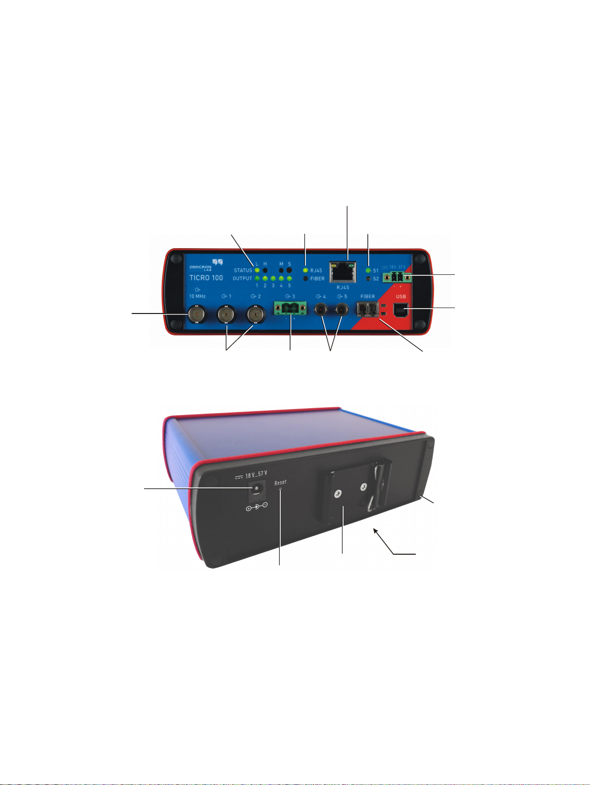
Omicron Lab TICRO 100 User manual

Smart Measurement Solutions®
TICRO 100
Quick Start Guide

Manual Version: ENU 1098 03 01
© OMICRON Lab 2018. All rights reserved.
This quick start guide is a publication of OMICRON electronics GmbH.
This quick start guide represents the technical status at the time of printing. The product information,
specifications, and all technical data contained within this quick start guide are not contractually
binding. OMICRON electronics reserves the right to make changes at any time to the technology and/
or configuration without announcement. OMICRON electronics is not to be held liable for statements
and declarations given in this quick start guide. The user is responsible for every application described
in this quick start guide and its results. OMICRON electronics explicitly exonerates itself from all
liability for mistakes in this quick start guide.
Please feel free to copy and print this document for your needs.
Windows is a registered trademark of Microsoft Corporation. Apple and Bonjour are registered
trademarks of Apple Inc. OMICRON Lab and Smart Measurement Solutions are registered trademarks
of OMICRON electronics GmbH.
TICRO 100 Quick Start Guide
2OMICRON

Contents
Compliance statement ........................................................................................................ 4
Recycling ............................................................................................................................ 4
1Introduction ...................................................................................................................... 5
1.1 About this quick start guide ................................................................................................ 5
1.2 General safety instructions ................................................................................................. 5
1.3 About TICRO 100 ............................................................................................................... 6
2Device description ........................................................................................................... 7
2.1 Device overview ................................................................................................................. 7
2.2 LEDs on the front side ........................................................................................................ 8
2.3 Connectors on the front side .............................................................................................. 10
2.4 Connectors and operating elements on the rear side ........................................................ 13
3 Mounting ........................................................................................................................... 14
3.1 DIN rail mounting ................................................................................................................ 14
3.2 Wall mounting ..................................................................................................................... 15
4 Power supply .................................................................................................................... 16
4.1 Power supply via Power over Ethernet .............................................................................. 16
4.2 Power supply via the delivered plug-in power supply unit .................................................. 17
4.3 Power supply via an external DC supply voltage ............................................................... 17
4.4 Using TICRO 100 as a PoE power source according to IEEE 802.3af .............................. 17
5 Accessing the Web Interface .......................................................................................... 18
5.1 System requirements ......................................................................................................... 18
5.2 Accessing the TICRO 100 Web Interface .......................................................................... 18
6 Troubleshooting ............................................................................................................... 21
6.1 Troubleshooting procedures .............................................................................................. 21
6.2 Performing a factory reset (reset to factory defaults) ......................................................... 23
Support .............................................................................................................................. 24
Contents
OMICRON 3

Compliance statement
Declaration of Conformity (EU)
The equipment adheres to the guidelines of the council of the European Community for meeting the
requirements of the member states regarding the electromagnetic compatibility (EMC) directive and
the RoHS directive.
FCC Compliance (USA)
This equipment has been tested and found to comply with the limits for a Class A digital device,
pursuant to part 15 of the FCC Rules. These limits are designed to provide reasonable protection
against harmful interference when the equipment is operated in a commercial environment. This
equipment generates, uses, and can radiate radio frequency energy and, if not installed and used in
accordance with the instruction manual, may cause harmful interference to radio communications.
Operation of this equipment in a residential area is likely to cause harmful interference in which case
the user will be required to correct the interference at his own expense.
Changes or modifications not expressly approved by the party responsible for compliance could void
the user's authority to operate the equipment.
Declaration of Compliance (Canada)
This Class A digital apparatus complies with Canadian ICES-003.
Cet appareil numérique de la classe A est conforme à la norme NMB-003 du Canada.
Recycling
This equipment (including all accessories) is not intended for household use.
At the end of its service life, do not dispose of the device with household
waste!
For customers in EU countries (incl. European Economic Area)
OMICRON test sets are subject to the EU Waste Electrical and Electronic
Equipment Directive (WEEE directive). As part of our legal obligations under this
legislation, OMICRON offers to take back the device and ensure that it is disposed
of by authorized recycling agents.
For customers outside the European Economic Area
Please contact the authorities in charge for the relevant environmental regulations in
your country and dispose the OMICRON device only in accordance with your local
legal requirements.
TICRO 100 Quick Start Guide
4OMICRON

1 Introduction
1.1 About this quick start guide
This TICRO 100 Quick Start Guide provides short information on how to install and use TICRO 100. It
is intended as an aid for the user to install TICRO 100 and take it into operation quickly and easily.
The TICRO 100 Quick Start Guide thus provides only a small subset of information available for
TICRO 100. It cannot substitute the TICRO 100 User Manual.
Therefore, also read the TICRO 100 User Manual in addition to this Quick Start Guide. The
TICRO 100 User Manual provides extensive and more detailed information about TICRO 100, its
installation and intended use, and how to configure and operate it. The TICRO 100 User Manual is
available in PDF format on the CD ROM delivered with TICRO 100 or can be accessed directly from
the TICRO 100 Web Interface.
1.2 General safety instructions
Before operating TICRO 100, carefully read the following general safety instructions:
•TICRO 100 may only be used in a safe technical condition taking into account its defined purpose,
safety requirements and possible risks as well as the operating instructions given in this Quick
Start Guide.
•TICRO 100 is exclusively intended for the applications specified in chapter "Introduction and
designated use" of the TICRO 100 User Manual. The manufacturer or the distributors are not
liable for damage resulting from unintended usage. The user alone assumes all responsibility and
risks.
• The instructions provided in this manual are considered part of the rules governing proper usage.
• Do not open TICRO 100. Opening the device invalidates all warranty claims.
• Do not carry out any modifications or adaptations to TICRO 100.
• Do not use any other power supply options for TICRO 100 than the ones described in chapter
Power supply on page 16.
•TICRO 100 is a SELV device (Safety Extra Low Voltage) which can be supplied with power by
Power over Ethernet (PoE class 3 powered device according to IEEE 802.3af). The ETH network
port of TICRO 100 may only be connected to Ethernet network ports or Power over Ethernet
power supplies.
• The FIBER network port and the outputs 4 and 5 are products of laser class 1 (IEC 60825).
WARNING
Death or severe injury caused by high voltages possible.
All inputs and outputs of TICRO 100 are electrically connected to the SELV (safety
extra low voltage) insulation group of the device.
►Do not connect any voltages that are not SELV compliant.
Introduction
OMICRON 5

1.3 About TICRO 100
TICRO 100 is a Precision Time Protocol (PTP) time converter that allows you to derive a high variety
of time codes from IEEE 1588/PTP packages received via Ethernet. This device enables you to easily
synchronize non-PTP equipment to the grandmaster clock of an IEEE 1588/PTP infrastructure.
TICRO 100 is designed for the following applications:
• Generation of PTP-synchronized signals to make existing equipment PTP capable.
TICRO 100 can be used to generate several time synchronization signals (e.g., PPX, IRIG-B,
DCF77, etc.) required for existing equipment (e.g., IEDs) from an IEEE 1588/PTP infrastructure.
• Synchronization of measurements.
TICRO 100 provides programmable trigger functionality that can be used for example to start
measurements at different locations at exactly the same time.
• Generation and distribution of 10 MHz reference frequency signals over Ethernet.
TICRO 100 provides a highly accurate 10 MHz reference signal that can be used to synchronize
measurement equipment such as synthesizers, frequency counters or spectrum analyzers to the
same frequency reference signal.
• Portable time code generation.
Together with a portable PTP grandmaster clock (e.g., OTMC 100 from OMICRON Lab),
TICRO 100 can be used to perform quick time synchronized measurements in the field.
1PPx IED
IED
IRIG-B
Measurement Measurement
10 MHz
IEEE 1588/PTP
10 MHz
1 PPx
IRIG-B
DCF77
IEEE 1588/PTP
Example: Generation of PTP-synchronized signals for existing
equipment Example: Synchronization of measurements
Example: Portable time code generation
Example: Generation of 10 MHz reference frequency
= PTP grandmaster clock = TICRO 100
Key:
TICRO 100 Quick Start Guide
6OMICRON

2 Device description
2.1 Device overview
10 MHz output
50 BNC socket
W
Output 1 and 2
50 BNC socket
W
Output 4 and 5
Optical outputs
ST connector, 820 nm
Output 3
Optocoupler
output
USB connector
(USB 2.0 type B)
100Base-FX
optical fiber Ethernet port
DC power input
(18 ... 57 VDC)
Device status LEDs
S1 & S2
10/100Base-TX
twisted-pair Ethernet port
LEDs indicating the
active Ethernet port
Status LEDs and
output status LEDs
Reset pushbutton DIN rail clip
Type plate with serial number
on bottom side
Mounting wholes for
wall mounting brackets
(covered by sealing plug)
DC power input for
plug-in-power supply unit
TICRO 100 does not provide an ON/OFF switch! The device automatically powers up after supply
voltage is provided via one of the DC power inputs or via Ethernet (PoE).
Refer to the following subsections for detailed information about the LEDs, connectors and operating
elements of TICRO 100.
Device description
OMICRON 7

2.2 LEDs on the front side
LED Description
S1 and S2 Green and red LED indicating the general device status according to the following
code.
S1 (green) S2 (red) Meaning
off off TICRO 100 not is supplied with power or device reboot is
requested.
off on Device is booting (normal boot process after applying
supply voltage or after reboot).
on off TICRO 100 is ready for operation (boot process finished
and device is operational). Observe the other LEDs for
information about the PTP clock status, the status of the
Ethernet connection and the output states.
on on Device is booting in recovery mode. Intermediate state
when initiating a factory reset (see "Operating procedures
performed directly on the device" in the TICRO 100 User
Manual).
blinking off Device is in recovery mode, waiting for new software. In
the recovery mode, the device provides only a rudimentary
Web Interface just allowing for the upload of a software
image.
off blinking Software update is in progress.
NOTICE
Equipment damage possible.
►Do not disconnect TICRO 100 from the power
supply or from the Ethernet or USB connection
during a software update.
blinking blinking Hardware error.
RJ45 and FIBER Green LEDs to indicate the currently active Ethernet port:
RJ45 for 10/100Base-TX (twisted-pair) or FIBER for 100Base-FX (optical fiber).
Only one Ethernet port can be used at a time. The Ethernet port actually
used has to be selected in the Web Interface (see "Network Configuration
page" in the TICRO 100 User Manual).
LEDs on the
Ethernet
connectors
The green LED indicates the Ethernet connection status (link status). The yellow
LED indicates that data traffic is active on the interface.
TICRO 100 Quick Start Guide
8OMICRON

LED Description
Status L and H Green LEDs to indicate the PTP status of the device:
L: Indicates the Locked state. TICRO 100 receives PTP time information from a
PTP grandmaster clock and is locked to this signal. It is able to provide its defined
accuracy. TICRO 100 is synchronized to the received PTP time signal.
The LED starts blinking as soon as TICRO 100 has established connection to a
PTP grandmaster clock and started its locking algorithm. As soon as an accuracy of
better than 1 µs is reached, the LED stops blinking. The typical overall accuracy
(better than 200 ns) is reached after approximately 30 seconds (with heated
internal oscillator (OCXO), see note below). However, please note that the absolute
overall system accuracy depends on the accuracy of the PTP grandmaster clock
and the PTP compliance of the network infrastructure.
TICRO 100 is equipped with an oven-controlled oscillator (OCXO). To
ensure precise time synchronization, TICRO 100 will only lock to the PTP
time signal after an initial heat-up phase for the OCXO. The duration of
this heat-up phase depends on the ambient temperature and is typically
5 - 7 minutes.
H: Indicates the Hold-over state. If TICRO 100 was in the Locked state before, it
enters the Hold-over state if synchronization to the PTP time signal gets lost. If
configured in the output configuration, TICRO 100 continues to output time signals
during the Hold-over state. However, synchronization of these output signals is then
performed using the internal oscillator (OCXO) instead of the PTP time signal. The
maximum hold-over duration depends on the time TICRO 100 was in the Locked
state before:
• Locked state ≤1 h: Hold-over time = 1 min ("mini hold-over").
• Locked state > 1 h and operating time (uptime) > 2 h: Hold-over time = half the
operating time.
• Locked state > 1 h and operating time > 48 h: Max. hold-over time = 24 h.
The "unconsumed" hold-over time remaining on the return to the Locked state ist
kept and extended by the "locked" duration as stated above.
Status M and S M: LED for future use. Currently without function.
S: Indicates that TICRO 100 receives a PTP signal, is connected to a PTP
grandmaster, and has taken over the role of a slave clock.
Output 1 to 5 Green LEDs to indicate which outputs are currently active.
Outputs can be disabled or muted in the Web Interface or automatically deactivated
by TICRO 100 if it is not able to provide time signals with sufficient accuracy. For
more detailed information, please refer to section "Output configuration page" of the
TICRO 100 User Manual.
Device description
OMICRON 9

2.3 Connectors on the front side
WARNING
Death or severe injury caused by high voltages possible.
All inputs and outputs of TICRO 100 are electrically connected to the SELV (safety
extra low voltage) insulation group of the device.
►Do not connect any voltages that are not SELV compliant.
Connector Description
10 MHz output (50 ΩBNC socket).
This output provides a highly accuracte 10 MHz sine wave signal
(4 dBm ± 2 dB at 50 Ω). The 10 MHz output is always active and cannot be
configured in the Web Interface.
Output 1 and 2 (50 ΩBNC socket).
Outputs 1 and 2 can be configured in the Web Interface for the following
signals:
- IRIG-B, unmodulated TTL signal or modulated on 1 kHz carrier
- PPX (TTL signal, adjustable number of pulses, for example, 1 PPS or 1 kHz)
- DCF77 unmodulated TTL signal
- Trigger (TTL signal, 1 pulse at a defined point in time)
- Trigger (TTL signal, PPX sequence starting at the defined point in time)
For information about configuring these outputs, please refer to section
"Output configuration page" of the TICRO 100 User Manual.
Output 3 (optocoupler output 30 V/100 mA max., terminal block supplied on
delivery).
Output 3 can be configured in the Web Interface for the following signals:
- IRIG-B unmodulated
- PPX (adjustable number of pulses, for example, 1 PPS or 1 kHz)
- DCF77 unmodulated
- Trigger (1 pulse at a defined point in time)
- Trigger (PPX sequence starting at the defined point in time)
For information about configuring this output, please refer to section "Output
configuration page" in the TICRO 100 User Manual.
TICRO 100 Quick Start Guide
10 OMICRON

Connector Description
Optical output 4 and 5 (ST connector, 820 nm).
Outputs 4 and 5 can be configured in the Web Interface for the following
signals:
- IRIG-B unmodulated
- PPX (adjustable number of pulses, for example, 1 PPS or 1 kHz)
- DCF77 unmodulated
- Trigger (1 pulse at a defined point in time)
- Trigger (PPX sequence starting at the defined point in time)
For information about configuring these outputs, please refer to section
"Output configuration page" of the TICRO 100 User Manual.
RJ45: 10/100Base-TX twisted-pair Ethernet port (RJ45 socket).
FIBER: 100Base-FX optical fiber Ethernet port (ST connector, 820 nm).
The LEDs indicate the link status and data traffic.
TICRO 100 can use only one Ethernet port at a time.
If no Ethernet port is selected in the Web Interface, the RJ45
Ethernet port is the default port if TICRO 100 does not detect an
operating Ethernet network on any of the network ports during the
first power-up or after a factory reset. It is strongly recommended to
set the network port in the Web Interface manually during
commissioning (see section "Network configuration page" in the
TICRO 100 User Manual).
USB port (USB 2.0, type B). Use this interface as an alternative for
connecting a computer to TICRO 100 (instead of accessing TICRO 100 via
Ethernet).
Access via the USB port can be disabled in the security configuration (see
Access Restrictions tab in section "Security configuration page" of the
TICRO 100 User Manual).
When accessing the TICRO 100 Web Interface via the USB port,
you should take care that the computer is not connected to the
Ethernet network TICRO 100 is connected to. The computer must
not be connected to TICRO 100 over the Ethernet network and the
USB port at the same time!
Device description
OMICRON 11

Connector Description
DC power input socket (MC 1.5/2-STF-3.81, connector supplied on delivery).
The correct polarity is printed on the front plate.
You can use this connector to connect a 18 ... 57 VDC supply voltage, either
as an alternative to the plug-in power supply unit supplied on delivery (DC
power input socket on rear side), or in addition to the plug-in power supply
unit to provide power supply redundancy for TICRO 100. For more details,
please refer to chapter Power Supply on page 16.
WARNING
Death or severe injury caused by high voltages possible.
►Use a power supply unit that complies with the SELV
standard if product safety according to IEC 61010-1 and
IEC 60255-27 is required. The plug-in power supply unit
supplied on delivery complies with the SELV standard.
NOTICE
Equipment damage possible.
The DC power inputs of TICRO 100 are protected against polarity reversal
if only one input is used at a time.
►When using both DC power inputs, make sure to observe the correct
polarity for both inputs. Reversed polarity on one of the DC power
inputs would make the reverse polarity protection ineffective and could
damage TICRO 100.
TICRO 100 Quick Start Guide
12 OMICRON

2.4 Connectors and operating elements on the rear side
Element Description
The reset pushbutton can be accessed through the hole in the rear panel
using a thin pointed object like the wire of a resistor with a diameter < 0.9 mm,
for example. The reset pushbutton can be used to:
• Initiate a device reboot.
• Initiate a factory reset to reset the device configuration to the factory
defaults (for example, if you forgot your password).
Please refer to section "Operating procedures performed directly on the
device" of the TICRO 100 User Manual for more detailed descriptions.
DC power input socket (standard DC barrel jack 2.5 x 5.5 x 11 mm, center pin
positive). Permitted voltage range: 18 ... 57 VDC
Use this input to connect the plug-in power supply unit supplied on delivery if
TICRO 100 is not supplied via Power over Ethernet (PoE). You can also use
the DC power input on the front side as a second DC source in addition to this
DC power input to provide power supply redundancy for TICRO 100. For
more details, please refer to chapter Power supply on page 16.
WARNING
Death or severe injury caused by high voltages possible.
►Use a power supply unit that complies with the SELV
standard if product safety according to IEC 61010-1 and
IEC 60255-27 is required. The plug-in power supply unit
supplied on delivery complies with the SELV standard.
NOTICE
Equipment damage caused by overvoltage possible.
This DC power input socket does not fulfill the surge requirements of
IEC 60255-27.
►Use the DC power input socket on the front side if IEC 60255-27
compliance is required.
NOTICE
Equipment damage possible.
The DC power inputs of TICRO 100 are protected against polarity reversal
if only one input is used at a time.
►When using both DC power inputs, make sure to observe the correct
polarity for both inputs. Reversed polarity on one of the DC power
inputs would make the reverse polarity protection ineffective and could
damage TICRO 100.
Device description
OMICRON 13

3 Mounting
3.1 DIN rail mounting
Proceed as follows to mount TICRO 100 to a 35 mm DIN rail (acc. to EN 50022):
1. Place the DIN rail clip supplied on delivery to the rear side of TICRO 100 as shown in the figure
below and align it with the mounting holes. The spring side of the DIN rail clip must point towards
the DC power input socket!
2. Use the two M3x12 screws to fasten the DIN rail clip to TICRO 100 (TX10 screwdriver required).
Do not use other screws than delivered with the DIN rail clip!
3. Hook the spring side of the DIN rail clip to the top side of the DIN rail.
4. Press the device downwards and then towards the DIN rail until the clip audibly snaps onto the
DIN rail.
Proceed as follows to remove TICRO 100 from the DIN rail:
1. Compress the spring of the DIN rail clip by pressing TICRO 100 downwards.
2. Release the bottom side of the clip from the DIN rail and withdraw TICRO 100 upwards.
DC power input socket
DIN rail clip with screws
TICRO 100 Quick Start Guide
14 OMICRON

3.2 Wall mounting
A wall mounting kit with four mounting brackets is provided on delivery for mounting TICRO 100 on flat
surfaces, for example on a wall.
Please observe the instructions included in the wall mounting kit for attaching the mounting brackets to
TICRO 100. Proceed as follows:
1. At the desired mounting positions for the mounting brackets, remove two sealing plugs on the rear
side and two sealing plugs on the front side of TICRO 100.
2. Unscrew the four uncovered screws from TICRO 100.
3. Insert the four sealing rings included in the mounting kit to the mounting holes of TICRO 100.
4. Fasten the mounting brackets using the delivered 22 mm long screws as shown below.
5. Mount TICRO 100 to the wall.
Remove 2 sealing plugs
from the mounting holes
on the rear side
Wall mounting kit
Remove 2 sealing plugs from the
mounting holes on the front side TICRO 100 with mounting brackets
Mounting
OMICRON 15

4 Power supply
TICRO 100 does not provide an ON/OFF switch! The device automatically powers up after supply
voltage is applied.
There are three possibilities to supply TICRO 100 with power:
1. Power supply via Power over Ethernet (PoE).
2. Power supply via the plug-in power supply unit provided on delivery.
3. Power supply via any suitable external DC supply voltage.
You can supply TICRO 100 using only one of these power supply options or using a combination of
two or all three options to provide power supply redundancy. When supplied by two external power
supplies (options 2. and 3. above), TICRO 100 automatically switches to the other source without any
interruption if one power source fails. If supplied via PoE and an external power supply (option 1. and
2. or option 1. and 3.), TICRO 100 will reboot after switching from the external power supply (option 2.
or 3.) to PoE power supply (option 1.).
NOTICE
Equipment damage possible.
The DC power inputs of TICRO 100 are protected against polarity reversal if only one input is used
at a time.
►When using both DC power inputs, make sure to observe the correct polarity for both inputs.
Reversed polarity on one of the DC power inputs would make the reverse polarity protection
ineffective and could damage TICRO 100.
If powered via the delivered plug-in power supply unit or by an external DC supply voltage,
TICRO 100 is able to operate as a power sourcing equipment (PSE) for class 1 devices
according to IEEE 802.3af.
4.1 Power supply via Power over Ethernet
The easiest method for supplying TICRO 100 with power is via Power over Ethernet (PoE) according
to IEEE 802.3af. Power supply via PoE does not require any additional cabling since it uses the same
cable (RJ45 port) for Ethernet communication and power supply.
Power supply via PoE is not possible if you are using an optical fiber Ethernet network.
The Ethernet network port used to supply TICRO 100 (i.e., the network port TICRO 100 is connected
to) must be able to supply a class 3 powered device (power consumption < 13 W).
If no suitable PoE source (e.g., an Ethernet switch) is available, it is also possible to insert a suitable
PoE injector between the Ethernet port on the network side and the Ethernet port of TICRO 100. A
PoE injector is not included in the scope of delivery.
TICRO 100 Quick Start Guide
16 OMICRON

4.2 Power supply via the delivered plug-in power supply
unit
Connect the plug-in power supply unit provided on delivery to the DC power input socket (standard DC
barrel connector) on the rear side of TICRO 100.
When connecting another power supply unit than the delivered one to this DC power input socket,
please observe the correct polarity (center pin is positive). The used power supply unit must deliver a
voltage of 18 ... 57 VDC with an output power of at least 13 W.
WARNING
Death or severe injury caused by high voltages possible.
►Use a power supply unit that complies with the SELV standard if product safety
according to IEC 61010-1 and IEC 60255-27 is required. The plug-in power supply
unit supplied on delivery complies with the SELV standard.
NOTICE
Equipment damage caused by overvoltage possible.
The DC power input socket on the rear side does not fulfill the surge requirements of IEC 60255-27.
►Use the DC power input socket on the front side if IEC 60255-27 compliance is required.
4.3 Power supply via an external DC supply voltage
TICRO 100 can also be supplied by an external DC supply voltage using the DC power input socket
on the front side. A corresponding two-pin connector (MC 1.5/2-STF-3.81) is provided on delivery. The
correct polarity is printed on the front plate.
The DC supply voltage must be in a range of 18 ... 57 V and deliver a power of at least 13 W.
WARNING
Death or severe injury caused by high voltages possible.
►Use a power supply unit that complies with the SELV standard if product safety
according to IEC 61010-1 and IEC 60255-27 is required. The plug-in power supply
unit supplied on delivery complies with the SELV standard.
4.4 Using TICRO 100 as a PoE power source according to
IEEE 802.3af
If powered via the delivered plug-in power supply unit or by an external DC supply voltage as
described in the sections above, TICRO 100 is able to operate as a power sourcing equipment (PSE)
according to IEEE 802.3af. The device is then able to power a class 1 device via its 100BaseTX
Ethernet port. This becomes especially handy if you operate TICRO 100 with the antenna-integrated
PTP grandmaster clock OTMC 100 from OMICRON Lab.
Power supply
OMICRON 17

5 Accessing the Web Interface
TICRO 100 automatically powers up after supply voltage is applied. The green LED S1 lights up and
the red LED S2 is off when the device is ready for operation.
TICRO 100 can be configured and controlled completely via the Web Interface using a computer.
Under normal circumstances, no manual intervention at the device itself will be required.
5.1 System requirements
Your computer must fulfill the following requirements to access the TICRO 100 Web Interface:
• OMICRON Device Link installed (see chapter "OMICRON Device Link" of the TICRO 100 User
Manual).
OMICRON Device Link is always required for the initial access to TICRO 100. If a static
IP address is assigned to TICRO 100, the device can be accessed any time and from
any computer using this IP address.
• Web browser installed (Microsoft Edge, Mozilla Firefox 20 or higher, or Google Chrome version 31
or higher).
• For access via Ethernet network only:
Network port configured for operation in the network TICRO 100 is connected to.
• For access via USB only:
USB 2.0 port available. While accessing TICRO 100 via USB, the computer must not be
connected to the same Ethernet network TICRO 100 is connected to!
If you are accessing TICRO 100 from a Mac or Linux operating system supporting zeroconf,
you can access the Web Interface of TICRO 100 by entering http://<hostname>.local to the
address bar of your web browser. The default hostname is the device serial number. The
serial number is available on the type plate on the bottom side of TICRO 100 (labeled
"SerNo").
5.2 Accessing the TICRO 100 Web Interface
OMICRON Device Link is required for initial access to TICRO 100. If you know the IP
address of TICRO 100, it is alternatively also possible to access the device from a web
browser using its IP address (without using OMICRON Device Link).
Proceed as follows to access the TICRO 100 Web Interface using OMICRON Device Link:
1. Connect your computer to the network or to the USB port of TICRO 100.
(Please note: Access via the USB port may possibly be disabled in the TICRO 100 configuration
(see Access Restrictions tab in section "Security configuration page" of the TICRO 100 User
Manual)).
2. Supply your TICRO 100 with power (see Power supply on page 16).
TICRO 100 Quick Start Guide
18 OMICRON

3. If your computer is not connected via the USB port of TICRO 100: Connect your TICRO 100 to the
network your computer is connected to.
4. If necessary, install OMICRON Device Link on your computer. See chapter "OMICRON Device
Link" of the TICRO 100 User Manual.
5. Launch OMICRON Device Link.
6. OMICRON Device Link will automatically find and display your TICRO 100.
The vertical bar on the left displays the device status:
• Green bar: The device is online and ready for operation.
• Gray bar: The device is offline. Supply your TICRO 100 with power.
• Red bar: The device is online but not accessible due to incorrect IP configuration.
TICRO 100 is usually configured to obtain the IP address automatically. However, it is also
possible to assign a static IP address to TICRO 100. In this case, the following behavior applies:
When accessing TICRO 100 via Ethernet, OMICRON Device Link will find the TICRO 100, but
display a red bar to indicate that the device cannot be accessed.
►Click the TICRO 100 entry and select Configure IP.
OMICRON Device Link will then display an IP configuration page. In this page, select Use the
following IP address and enter the IP address of your TICRO 100, or enter an IP address of
your choice to assign a new IP adress to your TICRO 100. Click the Subnet mask field to
automatically fill a subnet mask and then click Apply to connect to TICRO 100.
Or
►Click the Add device button and enter the IP address assigned to TICRO 100.
Accessing the Web Interface
OMICRON 19

7. A green vertical bar indicates that OMICRON Device Link successfully connected to your
TICRO 100. Click the TICRO 100 entry and select Open Web Interface.
8. The Web Interface is opened in a web browser.
Password protection is disabled by default. If password protection is configured for TICRO 100, a
login dialog is displayed. Enter your password and click Login. The default password is
timeterminal.
9. The start page of the TICRO 100 Web Interface is displayed. You can now access all pages of the
Web Interface.
►Proceed with section "Next steps to set up TICRO 100" of the TICRO 100 User Manual to
configure TICRO 100 according to your needs.
►Use the Logout link in the top right corner to exit the TICRO 100 Web Interface (only available
if password protection is enabled).
TICRO 100 Quick Start Guide
20 OMICRON
Table of contents
Popular Media Converter manuals by other brands

Littfinski Daten Technik
Littfinski Daten Technik TurnTable-Decoder operation instruction

AB Quality
AB Quality Allen-Bradley 1771-DE user manual

Sony
Sony DVMC-DA2 Service manual

Tesla smart
Tesla smart HSP0104A1U manual

Kathrein
Kathrein CAP-Konverter Update manual

TR-Electronic
TR-Electronic LMRI-46 user manual