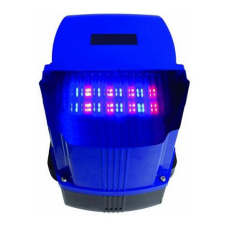
Omker OMK-K373 User manual

1
OMK-K373 Resistance Rebound Intelligent Built-in Controller for
Sliding Door
INSTRUCTION MANUAL
Read carefully
As newly developed product, OMK-K373type resistance rebound intelligent built-in
controller for sliding door is controlled by microcomputer with reliable performance,
resistance rebound compared with other liking products, it covers the following
advantages:
1. Anti-collision design: when the door body travel is completed, only after press reverse
key, the motor can be activated so that the over-travel can be avoided.
2. Motor time protection: the default value is 90s, if want to change this value, you
may reset as follows(When setting this value,the RED DIP switch 3 should be turn on
to OFF (This is very important)): Turn on Red DIP switch 6 to ON, press function key F
more than 5s,power indicator light will be off,after a sound of the controller,release function
key F, the door will automatically open to the limit and stop,then perform close
action,closing to close limit and then stop,complete setting of motor time protection.
After setting,you should turn on Red DIP switch 6 back to off. Noted: when setting travel
protection time,travel open and close limit should be installed and run normally. (Press
function key F more than 5s,if power indicator light do not turn off,you should cut off power
for 5s, and then connect power, entering this function).
3. Auto Close Function: If you need auto close when external card reader or other auto
release system is added, you should turn on RED DIP switch 3 (Auto close) to ON,star auto
close function.Then turn on RED DIP switch 6 (set) to ON, each time you press F,you will
hear a sound.How much time you want for the auto close how many times you press F.After
setting,you should turn on RED DIP switch 6 back to off,and will hear a sound. Auto close
time setting is finished. When door reach to the open limit, stop indicator light of the
controller will flash and timing ,when reach the setting time,the door will auto closed to
realize remote control function.(Noted setting of auto close function: you should reconnect
the power, otherwise it will have no reaction). It’s strongly recommended to add infrared
protection, especially when performing auto close function to avoid unnecessary loss.
4. Single key remote control and three key remote control interchange: This function
can be set by RED
DIP switch 1. Turn on RED DIP switch 1 (single key remote control )to off, remote
control perform in this way: OPEN-STOP-CLOSE-LOCK four keys controlled
independently.Turn on RED DIP switch 1 to ON, remote control perform single key cycle
operation, i.e.coded with which key,that is the key perform cycle operation.
For example:use OPEN key to coded
Press OPEN key=door open
Press OPEN key again =door stop

2
Press OPEN key once more=door close
Press OPEN key again=door open
Cycle in this way. When choosing single key control, one remote control can control at
most 4 gates.
For example, use OPEN to control gate 1, use CLOSE to control gate 2, use STOP to
control gate 3,use LOCK to control gate 4.
5. Manual single key function: you can choose normal open switch without electric voltage
like doorbell to connect with GND and ONE. Single key manual cycle operation:
OPEN-STOP-CLOSE-STOP.
6. Motor force adjustment(soft star force adjustment):(You should turn on RED DIP
switch 4 to ON).
Motor with soft star low speed function,star slowly and stop slowly,low speed force can
be adjusted by TORQUE potentiometer.Clockwise to increase the strength,(as the strength
increase,low speed function will not obviously ).Anti clockwise to decrease the strength(as
the strength decrease,low speed function will become obviously).If the gate is very big or
heavy,it is not recommend to use this function.
7. Resistance rebound function: (you should turn on RED DIP switch 5 to ON)
During closing of the motor,door will stop when meeting obstructions and rebound, to
ensure safe of person and vehicle.Resistance strength can be adjusted by FORCE
potentiometer, clockwise to increase the strength,anti clockwise to decrease the
strength.Strength adjust potentiometer (TORQUE) can adjust strength of the motor make
rebound more obviously.You can also turn on RED DIP switch 5 to OFF, turn off resistance
function.(Not recommend)
8. Anti-clamping function:During closing of the door, when there are obstructions blocks
the infrared rays, the door will automatically stop,and moves reversely in case of clamp
people or objects.It’s strongly recommended to add infrared anti-clamping function,
especially when performing auto close function to avoid unnecessary losses.
9.Adjust motor running direction without changing lines: If the door open and close in
opposite direction after installation, just turn the motor direction switch to the opposite
direction.
10. Adjust travel direction without changing lines: If the door travel in opposite direction
after installation, just turn the travel direction switch to opposite direction. (If LED, L1-L2
light up at the same time or open to the limit can stop but can’t close, close to the limit can
stop but can’t open,that is because magnet installation position is not correct,just make high
position magnet higher,and low position magnet Lower.
11.Travel connection:Travel can choose mechanical or reed switch(noted:normal open
connection,short of NC is normal close travel).Travel common line in the middle, left is for
open limit,right is for close limit.
You can also switch to single travel mode by P2 PIN. If one of the travel limits is
broken,you can switch to single travel mode,adjust position of t magnet or spring plate to the
same height,it will not affect normal use.
12.LED fault display: It is easy to carry out maintenance and use through LED screen.

3
Attention: Upper side connection terminals of the control board are input terminal,green
parts are single input , please do not connect with high voltage.The lower part of
the terminals are single output, green terminal is for alarm lamp output ,please do
not connect with 220V.
Technical parameters:
Input voltage :~220V±10%
Max. output current:10A
Remote distance:> 50m in open place(without same frequency signal interference)
RED DIP switch turn on to ON function:
1.Remote control single key function
2.Remote control lock key manual function
3.Auto close function
4.Soft star function
5.Resistance function during closing
6.Set

4
Using of the remote control:
The control board use the latest encrypted rolling code, unable to copy, more safe and
confidential. One control board can be coded with 298pcs of remote controls.
A、Remote control operation:press direction keys(CLOSE OPEN)of the remote
control to activate the motor, press STOP of the remote control the motor will stop.
B、Lock remote control: Turn on RED DIP switch 2 to ON,it is with lock function.Press
of the remote control,the control board into lock state.(Stop
indicator light of the control board flashing)That is manual button
and remote control direction keys are locked.It can be released by
press of the remote control.(Stop indicator light of the control
board stop flashing).When the control board is locked, only by
press of the remote control,direction keys of the remote control
and manual button of the control board can be used
normally.Even cut off the power,it is still in the state of lock.
(The control board is set without lock function in the factory )
C、Add remote control:Press white SN1 key of the control board(noted it is the study
/delete key) 1 second,power indicator light off, release your
hand,press any key of the remote control twice continuously as
soon as possible,hear a sound,study of the remote control
finished.Add more remote controls repeated the above operation.
If it is fixed code remote control,only need to weld with the same
code.
Tips for remote control study: 1. Do not let the remote control too
close to the control Board,it is better to press at your back. 2.
Press Lock key of the remote control within 1 second after
pressing study key of the control board. 3.After studying,do not
long press function key of the control board.
D、Delete all remote controls operation: Long press white SN1 study/delete key of the
control board,8s later you will hear a sound,delete all the remote controls.
V.Optional accessories and interface function instruction:
1. Access code lock use outlet button or inter phone to open the door (card reader optional
accessories,if added):Connect +12v power interface of the card reader to +12V power
interface of the control board, connect -12V power interface of the card reader to GND
power interface of the control board,connect PUSH/ON of the card reader to OPEN interface
of the control board (Noted: Access card reader should be compatible with control board of
our company,that is PUSH / ON output is a low voltage signal negative output).
2. Access code lock use outlet button or inter phone to open the door (card reader optional
accessories,if added):Connect +12v power interface of the card reader to +12V power
interface of the control board, connect -12V power interface of the card reader to GND
power interface of the control board,connect PUSH/ON of the card reader to CLOSE
interface of the control board (Noted: Access card reader should be compatible with control
board of our company,that is PUSH / ON output is a low voltage signal negative output).
Noted:When using card function,the control board can set auto close function. After swipe
card,the door will delay close automatically(Refer to auto close setting). If case of safe, it is

5
strongly recommend you to add safety infrared,in case of unnecessary losses during closing.
3. Button switch (Far distance button single key cycle function ): This control board with
far distance button control function, when you need to add external button ,connect button
switch to single key interface and public interface of the control board, button switch
perform in this way:
When the door close:-------------- Open, during opening:-------------------Stop
When the door open:-------------- Close, during closing:-------------------Stop
4. Ground sensor or infrared auto close interface: After the car (recommend to add ground
sensor) or person (recommend to add Infrared)passing, motor automatically close, using this
interface.Connect NO (Normal open) of the ground sensor or NO(Normal open) of the
infrared to ground sensor interface of the control board, connect COM of ground sensor or
COM of infrared to COM of the control board..When the door open to the limit,detecting
gate opener to the limit,if ground sensor interface input terminal has normal close signal
input,ground sensor will be function.When car or person leave ground sensor position or
infrared position,ground sensor function, after ground sensor or infrared signal remove 3s ,
motor star working, performing auto close.When signal terminal of the ground sensor detect
signal input, door will automatically stop and perform open action,open to the limit. Detect
ground sensor signal again,after ground sensor signal remove,perform auto close.
Use method for Infrared(electric eye 1 interface):
The control board can connected with infrared (connection as following ).
Jump the infrared to normal open,or connect to NO.
During closing of the motor, when photocell has action,the motor will stop 2s and then
perform opening.
Cautions:
1. The power supply is ~220V+10%, not connect to 380V.
2. The default time value of control box is 90s. The remote controller use battery of
DC12V, 27A , with one year service life. Keep the remote controller away from wet and
collision, if need change the password, please refer to password setting for details.
3. If the remote distance is too short, check if the motor installation site is covered by
metal object or close to metal object.

6
4. If the controller is out of order, try to reset or check if the battery has been used up.
5. Remote control distance shorter :
(1)Generally speaking, in the wide place( more than 50 meters), the effective distance may
fluctuate due to external influence like rain, flog, wind etc. that is normal.
(2)If the battery is old, the effective distance will become shorter, just replace it with a new
one.
Safeties & Cautions:
(1)All the operations must be implemented according to the instructions, this is very
important to personal safety.
(2)Please read instructions carefully before installation.
(3)Please keep the instructions properly for future use.
(4)Our product is in strict accordance with the instructions for the design and manufacture.
Any violation of the instructions may damage the product or cause dangers.
(5)Our company is out of responsibility for any operation or use violating the instructions.
(6)Installation must comply with relevant safety standard.
(7)All the machine fittings must comply with national standard related.
(8)Our company is out of responsibility for the consequences caused by user’s ignoring the
process requirements of precision components during operation.
(9)Safety devices (like photoelectric switch, sensor etc.)should be installed to avoid
damage.
(10)Any attempts to change the structure of the components is forbidden.
(11)The installation personnel should give detailed operation methods to the users as well
as the regulations under emergency, also the “instructions ”should offered.
(12)Only the operations indicated in INSTRUCTIONS are allowed.
(13 )During installation, keep the children and other unrelated person away from the
installation site.
(14)No unsafe factors around the installation site.
(15)Power supply should in accordance with the demand.
(16)Both the door opener and the door body must be well grounded.
Electric leakage as well as short protection device should be equipped.
(17 )Before electric control system operate, remove all the barriers within the door
covering area and any vehicles or person are forbidden to pass.
(18)Both the installation position and height of main control box should be proper, do not
be exposed to sunlight and rain, forbidden to let children to operate the remote
controller as well as control panel switch.
(19)If it is necessary to install a outer shield, consider that if it may shield signal of the
remote control.
(20)Keep the remote control away from children in case of accident.
(21)Any attempts to dismantle this machine privately is forbidden, only the professional
technician is allowed to make the maintenance.
(22 )Before system maintenance, cut off the power supply, and check if the grounding
system is correct.
Table of contents
Other Omker Gate Opener manuals
Popular Gate Opener manuals by other brands

SCS Sentinel
SCS Sentinel prim' OneGate 3 manual

Arrow
Arrow AL400AC Instructions and warnings for installation, use and maintenance

Beninca
Beninca BISON 35 OTI L manual

Seco
Seco SPARK 4 installation manual

Siemens
Siemens SMART GATE S-80 quick start guide

SEA
SEA Libra Mini Tank INSTALLATION MANUALS AND SAFETY INFORMATION