Omnik New Energy Co., Ltd. Omniksol-WIFIKIT User manual

User Manual V2.6
Omniksol –WIFIKIT User Manual
Omnik New Energy Co., Ltd.

Overview of WIFIKIT Function
Omniksol-WIFIKIT is developed by Omnik as an external communication monitoring device,
which integrates WiFi device for users and provides a wireless monitor function.
By connecting with inverters through RS485 interface, the Kit can receive information from
inverters and realize cascade of inverters. It can not only provide wireless function, but also
can use cable to transfer inverter data to the web server
Users can monitor the runtime status of the device by checking the 4 LEDs on the panel, that
indicates Power, RS485, Link and Status respectively.

1
Catalog
1 Communication cable connection ........................................................................................................2
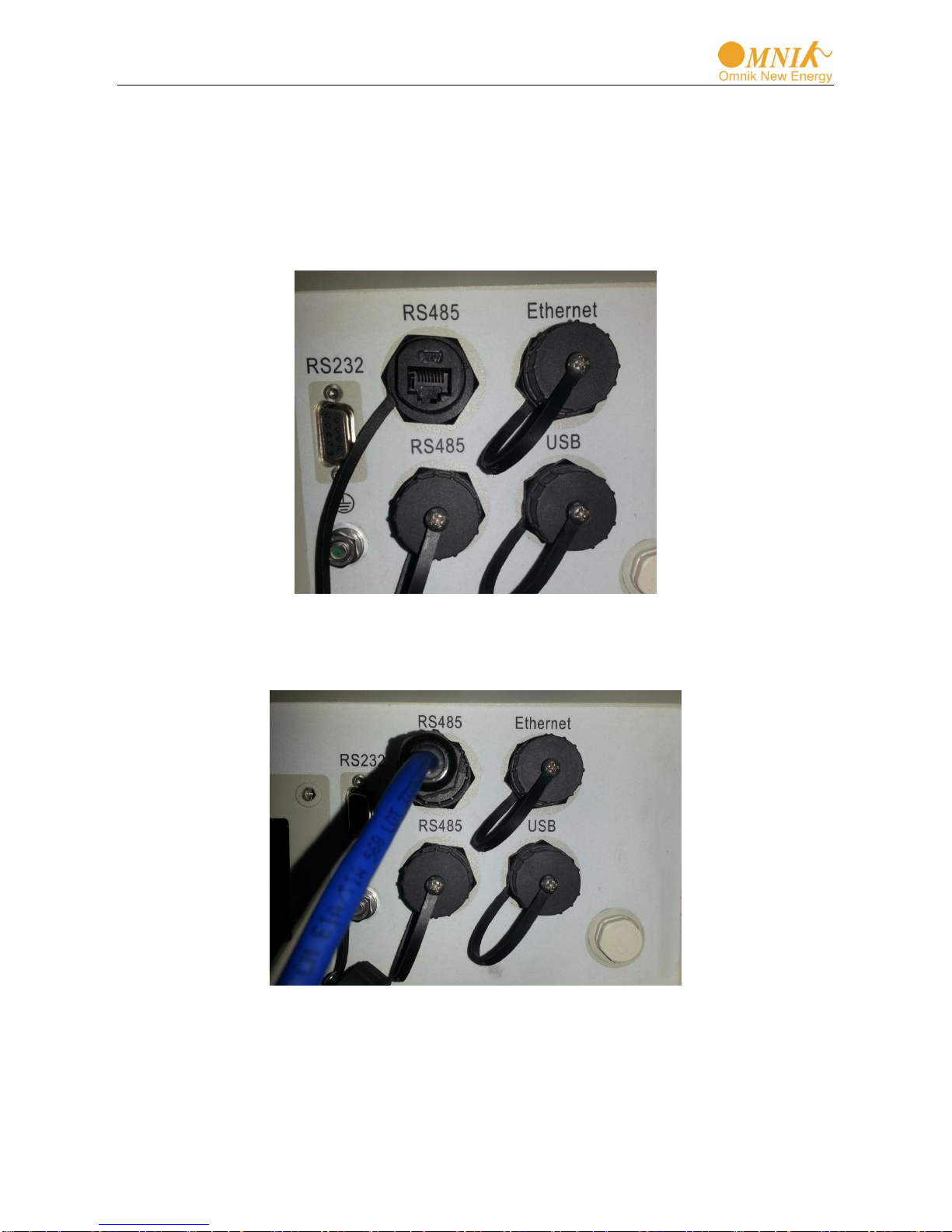
1.1 Inverter with RJ45 connector......................................................................................................... 2
1.1.1 Cable connector preparation ....................................................................................................2
1.1.2 Installation.................................................................................................................................5
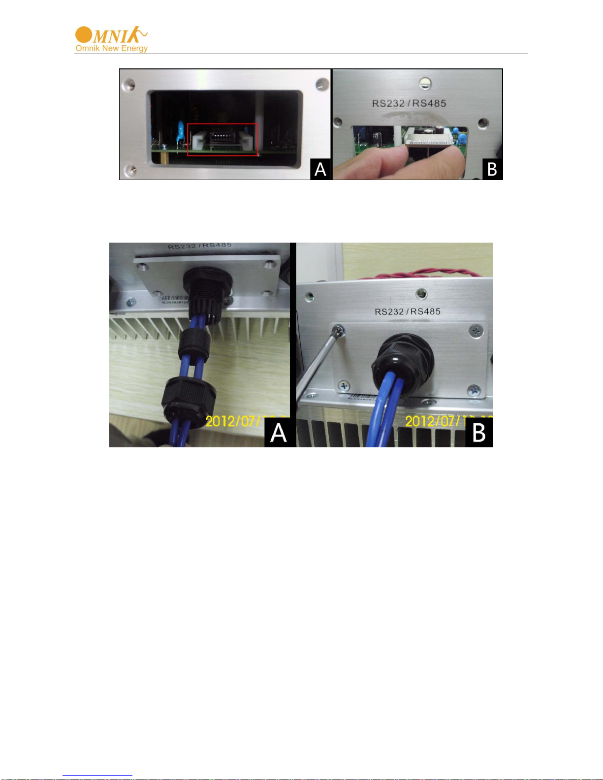
1.2 Inverter without RJ45 connector....................................................................................................6
1.2.1 Disassembly.............................................................................................................................. 6
1.2.2 Installation.................................................................................................................................7
2 Omniksol –WIFIKIT User Manual.........................................................................................................9
2.1 Unpack...........................................................................................................................................9
2.2 The installation of data collector....................................................................................................9
2.2.1 Wall-mounted installation..........................................................................................................9
2.2.2 Horizontal data collector installation.......................................................................................10
2.3 Connection between data collector and inverter.........................................................................10
2.3.1 The instructions of data collector interface and connection line interface .............................10
2.3.2 Steps of connection ................................................................................................................11
2.4 WiFi settings................................................................................................................................12
2.4.1 Wireless Network....................................................................................................................12
2.4.2 Wired network......................................................................................................................... 22
2.5 Debug .......................................................................................................................................... 23
2.6 Register on monitoring website...................................................................................................25
2.6.1 Click Register button to go to registering interface for new account................................... 26
2.6.2 Fill in user’s information as required .................................................................................... 26
2.7 Login the PV monitoring system to manage the power station...................................................28
2.8 IPhone & iPad application ...........................................................................................................33
3 Contact................................................................................................................................................35

2
1 Communication cable connection
1.1 Inverter with RJ45 connector
For Omnik inverters Omniksol-13k/17k/20k-TL, which has integrated RS485 card, the cable
connection of inverter is as following method.
1.1.1 Cable connector preparation
In order to satisfy IP65 level, the communication cable needs to be prepared particularly.
A. Find the LTW waterproof cable connector in the package of inverter. There are
two sets inside of each package. Then prepare appropriate length of RS485
communication cable which has no plug.
Picture 1.1.1

3
B. Put SEAL inside of HOUSING as Picture 1.1.2.
Picture 1.1.2
C. Put communication cable through Sealing Nut, SCREW, SEAL, HOUSING and
don’t tighten the Sealing Nut.
Picture 1.1.3
D. Put the cable terminal into the plug in right order as Picture 1.1.4
Picture 1.1.4
SEAL
HOUSING
Line sequence of T568B
1. orange with white
2. orange
3. green with white
4. blue
5. blue white white
6. green
7. brown with white
8. brown

4
E. Clamp plug by a cable clamp as Picture 1.1.5
Picture 1.1.5
F. Put the plug into HOUSING with GASKET as Picture 1.1.6.
Picture 1.1.6
G. Tighten Sealing Nut with torque 3Nm, here one connector is prepared. As
Picture 1.1.7.
Picture 1.1.7
H. In order to connect the cable to other inverter, please prepare the other
terminal by same method.

5
1.1.2 Installation
After the connector preparation, next is to connect the cable to inverter. Following steps
shows the installation method.
First open the cap of RS485, there is a RJ45 connector inside.
Picture 1.1.8
Then put the plug into RJ45 connector, tighten the SREW to inverter with torque 3Nm.
Picture 1.1.9
Complete the other connection by the same method.

6
1.2 Inverter without RJ45 connector
For Omnik inverters Omniksol-1k/1.5k/2k-TL, Omniksol-3k/4k/5k-TL, which has no
integrated RS485 card, the wire connection of inverter is as following method.
1.2.1 Disassembly
Picture 1.2.1
Unscrew the four screws on the interface panel with the screwdriver as shown in Picture
1.2.1 and keep the screws aside.
Picture 1.2.2

7
Picture 1.2.3
Unscrew the two-holed water-proofing connector from the interface panel as shown in
Picture 1.2.2, 1.2.3.
1.2.2 Installation
Pick out the net cable and the water-proofing connector from the package and follow the
Picture:
A. Put the net cable in from the gap
B. Put the net cable one after another into the neck of the interface panel
Picture 1.2.4
C. Insert the RS485 card lightly from the position as following picture

8
Picture 1.2.5
D. Finish the installation, as Picture 1.2.6:
Picture 1.2.6

9
2 Omniksol –WIFIKIT User Manual
2.1 Unpack
After unpacking the box, please check the parts according to the below list. Contact the
manufacturer immediately if you find any damage, missing or wrong model of the device or
any parts.
Serial
Name
Quantity
Model
A
PV data collector
1
WIFIKIT
B
Power supply adapter
1
FY0502000
C
screw
2
--
D
expanded rubber tube
2
--
E
manual
1
--
2.2 The installation of data collector
2.2.1 Wall-mounted installation
①Mark two horizontal round holes which distance is 69mm in the selected position
②Drill two φ6mm holes in the marked position, the depth of the hole is not less than 30mm
③Punch the expanded rubber tubes into the holes lightly with a rubber hammer
④Wring two screws into the expanded rubber tubes, the screws head exposed wall about
6mm
⑤Hang the PV data collector WIFIKIT on the screws,hold the metal part of the antenna
and rotate the antenna to a wanted position
Picture 2.2.1
Picture 2.1.1

10
2.2.2 Horizontal data collector installation
Lay the data collector on a flat surface.
Note1: The protection level of PV data collector WIFIKIT is IP21. It cannot be installed outdoors or in the
conditions of damp, dusty or with corrosive steam. Direct sunlight is also avoided, as well as shock and
pressure defense. In addition, as metal components have effect on the wireless signals, the antenna of
PV data collector (in all direction) should be away from metal components at least 10cm.
Note2: When screw or adjusting the antenna position, please note only the metal part can be screwed,
plastic part cannot be screwed, or the antenna will be damaged. In addition, the unusual installation status
will affect the usage of data collector; more details please refer to the abnormal condition and dispose
during debugging.
2.3 Connection between data collector and inverter
2.3.1 The instructions of data collector interface and connection line
interface
Serial
Instructions
A
RS485/422 interface
B
Ethernet
C
Reset
D
Power supply adapter interface
E
Antenna interface
Picture 2.3.1

11
2.3.2 Steps of connection
Both ends of the connecting wire are RJ45 network cable connector,all the line sequence
are T568B.
A. Single inverter connection
1) Cut off the power supply of the inverter
2) Insert the network cable into anyone RJ45 port on anyone inverter
3) Let the other network cable connects the network interface of PV data collector
WIFIKIT
4) Connect the power supply adapter to data collector, then insert into the socket
B. Multiple inverter connection
1) Cut off the power supply of the inverter
2) Insert the network cable into anyone RJ45 port on anyone inverter
3) Insert the other network cable into anyone RJ45 port on second inverter
4) Make the needed monitoring inverters in series in the same way
5) Connect the PV data collector WIFIKIT to a inverter with the bus,(constitute
serial LAN)
Pin NO.
RS485
RS422
1
NC
NC
2
NC
NC
3
NC
RX+
4
A
TX+
5
B
TX-
6
NC
RX-
7
GND
GND
8
GND
GND
Line sequence of T568B
1. orange with white
2. orange
3. green with white
4. blue
5. blue white white
6. green
7. brown with white
8. brown
RJ45 plug
Picture 2.3.2

12
6) Connect the power supply adapter to data collector, then insert into the socket
Picture 2.3.3
Note: Must cut off the power supply before connection. Please make sure that all the connections are
completed, and then power the inverters and PV data collectors. Otherwise may cause personal injury or
equipment damage.
2.4 WiFi settings
2.4.1 Wireless Network
1) Prepare a computer or device, e.g. tablet PC and smartphone that enables WiFi.
2) Obtain an IP address automatically
Open Wireless Network Connection Properties, double click Internet Protocol Version
4(TCP/IPv4)
Select Obtain an IP address automatically, and click OK
Picture 2.4.1
Insert the wifi part, turn on
DC power, 3minutes later
continue the next part

13
Picture 2.4.2
3) Open wireless network connection and click View Wireless Networks
Select wireless network of the data logging module, no passwords required as default. The
network name consists of AP and the serial number of the product. Then click Connect.

14
Picture 2.4.3
Picture 2.4.4
Connection successful

15
Notice: If AP_ (serial number of product) is not available in the wireless network list, there may be problems in
the connection or setting of data logging module. Please check if the WiFi had installed ok, and inverter has been
powered on.
Before troubleshooting, please inquire with your inverter installer whether you are allowed to
remove the cover of the inverter to trouble shoot the module. If not allowed, please contact
customer service.
4) Set parameters of WiFi module
(a) Open a web browser, and enter 10.10.100.254 (the default IP address of WiFi-Kit,
you may set domain name access, please see the picture 2.4.5), then fill in username:
admin and password: admin, both of which are admin as default.
Recommended browsers: Internet Explorer 8+, Google Chrome 15+, Firefox 10+
Note:
①In order to make sure the setting goes smoothly, you need to check following points:
Set your WiFi router to DHCP mode
For inverter without integrated RS485 card, confirm the RS485 card is installed well and do not loose in
the inverter
②The default username & password : admin, admin. We suggest modify the username & password:
Step: choose “Account”, input your username & password.
Picture 2.4.5
(b) In the configuration interface of WiFi module, you can view general information of the
module.
Follow the setup wizard to start quick setting.
admin
admin

16
Picture 2.4.6
Click Wizard to start
Picture 2.4.7
Choose Wireless Connection

17
Picture 2.4.8
Click Refresh to search available wireless networks, or add it manually input

18
Picture 2.4.9
Select the wireless network you need to connect, then click Next
Notice:
①If the signal strength (RSSI) of the selected network is <10%, which means unstable connection, please adjust
the antenna of the router, or use a repeater to enhance the signal.
②We recommend router setting:
Security setting: WPA2-personal
Encryption type: AES
Table of contents
Popular Measuring Instrument manuals by other brands

Satec
Satec BFM II EM Operation and installation manual

SPARLING
SPARLING Tigermag FM656 Installation, operation & maintenance manual

Corelis
Corelis BusPro-I user manual

Econ
Econ sens3 operating instructions

Tektronix
Tektronix DSA8300 Quick start user manual

PCB Piezotronics
PCB Piezotronics 339B01 Installation and operating manual