manuals.online logo
Brands
  1. Home
  2. •
  3. Brands
  4. •
  5. SATO KEIRYOKI
  6. •
  7. Measuring Instrument
  8. •
  9. SATO KEIRYOKI SK-93F-II User manual

SATO KEIRYOKI SK-93F-II User manual

Instruction Manual
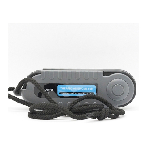
No. 7687-10 Vane Type Thermo-Anemometer
Model SK-93F-II
No. 3 Nishi-Fukudacho, Kanda, Chiyodaku, Tokyo 101-0037 Japan
URL: http://www.sksato.co.jp/english/
1
Thank you for purchasing the SK-93F-II Vane Type Thermo-Anemometer.
-This product is designed to measure wind speed, air flow and temperature. Do not
use it for other purposes.
-Read this manual carefully before using the SK-93F-II. Keep the manual in a safe place for
future reference whenever necessary.
Features
-Compatibility between main unit and sensor probe
The main unit and sensor probe are fully compatible. When using multiple SK-93F-II units, the
measurement accuracy always falls into the acceptable accuracy range even if the main unit or sensor
probe of one SK-93F-II unit is combined with the main unit or sensor probe of another SK-93F-II unit.
-Measurement of air flow
By entering/setting the value of the cross-section to be measured, the air flow can be calculated from
measured wind speed and displayed. (See “Measuring air flow”)
-Measuring the maximum, minimum, and mean values
The maximum, minimum, and mean values measured during wind speed, airflow rate, or temperature
measurement can be displayed. (See “Measuring and Storing Maximum, Minimum, and Mean Values”)
-RS-232C output
By using the dedicated RS-232C connecting cable (option), measured values can be imported into a
personal computer in real time, thus allowing real-time monitoring of wind speed and temperature. Note,
however, that users must write a communication program by themselves. (See “RS-232C Output”)
-Auto power-off function
If none of the function keys are pressed for approximately 15 minutes, the auto power-off function will be
activated, causing the power to shut off automatically. This prevents the battery power from being
drained in case the user forgets to turn off the power. (See “Auto Power-off”.)
-Sensor probe error display
If a sensor probe error such as disconnection occurs, the corresponding error code will appear on the
LCD display, enabling the user to identify the cause of the error. (See “Error Codes”)
- Auto hold function
This function can hold (freeze) measured values on the display. (See “Holding Displayed Values”)
2
1. Names and Functions of Components
Main Unit
(1) Vane-type wind speed and temperature sensor probe connector
Connects the dedicated sensor probe.
(2) AC adapter jack
Connects the dedicated AC adapter. For details on the AC adapter, see “Using an AC Adapter”.
(3) RS-232C cable connection jack
Connects the RS-232C cable. For details on the RS-232C cable, see “Connection Method”.
(4) LCD Display panel
Displays measured values and the operating status of this device.
(5) Function keys
Used to set or select each function.
(6) Battery lid
A lid on the 9-V battery (6F22 ) compartment. Remove the screw with a Phillips screwdriver, fit the
battery, and reinstall the lid.
(7) Vane-type wind speed and temperature sensor probe
Wind speed is measured by monitoring the revolving vane (propeller).A thermistor is used as the
temperature sensor.
(8) Vane-type wind speed and temperature sensor probe plug
Connect this plug to connector (1) on the main unit.
3
LCD Display Panel
(9) 7-segment display (upper part)
Displays a wind speed or airflow rate. It displays the entered cross-sectional area in cross-section input
mode, or a stored value in data storage mode.
(10) 7-segment display (lower part)
Displays a temperature value. It displays the number of stored values in data storage mode.
(11) Unit of wind speed or air flow
Displays “m/s” or “ft/m” for the unit of wind speed, “cms” or “cfm” for the unit of air flow, and “m2”or “ft2”
for the unit of cross-sectional area.
(12) Unit of temperature: Displays °C for the unit of temperature.
(13) vel: Lit while in wind speed measurement mode.
(14) FLOW: Lit while in air flow measurement mode.
(15) AREA : Lit while in cross-section input mode, which is used for measuring air flow.
(16) Hold: Lit while each measured value is being held (frozen).
(17) REC: Lit while a minimum measured value (MIN), maximum measured value (MAX), or mean
measured value (AVG) is being stored.
(18) MIN: Lit while a minimum wind speed or minimum airflow rate value, and a minimum temperature
value are being displayed.
(19) MAX: Lit while a maximum wind speed or maximum airflow rate value, and a maximum temperature
value are being displayed.
(20) AVG: Lit while a mean wind speed or mean airflow rate value, and a mean temperature value are
being displayed.
4
Function Key Panel
(A) POWER/RESET key
POWER: When this device is off, pressing this key turns the power on. Pressing it again
turns the power off.
RESET: While in maximum/minimum/mean value measurement mode, pressing this key clears the
maximum, minimum, and stored mean values.
(B) MODE key
This key allows you to select wind speed measurement mode (“VEL”), cross-section input mode
(“AREA”), or air flow measurement mode (“FLOW”).
(C) HOLD/ADVANCE key
HOLD: Pressing this key holds (freezes) the displayed value while in wind speed measurement
mode or air flow measurement mode.
ADVANCE: This key is used to enter a cross-sectional area while in cross-section input mode.
Each time the key is pressed, the value increments (0 to 9).
(D) MIN/MAX RECORD/SINGLE POINT key
Pressing this key displays the maximum and minimum measured wind speed (or airflow rate) and
temperature values.
(E) NEXT DIGIT MULTI-POINTAVERAGE key
NEXT DIGIT :This key is used to move the cursor to the next cross-sectional area digit while in
cross-section input mode.
MULTI-POINTAVERAGE: This key is used to display the stored mean wind speed (or air flow) and
temperature values.
5
2. Notes on Use
To ensure correct use of this device, observe the following items.
-Because this device is a precision measuring instrument, be careful not to drop it or apply vibration
or shock.
-Do not disassemble or modify this device. Doing so may result in failure.
-Do not use this device in a place exposed to direct sunlight or near heating equipment. Doing so may
not only prevent correct measurement but will also cause deformation and discoloring of the casing.
-The operating temperature range for this device is 0 to 50°C at the humidity of 80% RH or less.
Using the device outside the range will result in failure.
-Do not use this unit in an environment where electrical noise is generated. Doing so may result in
unstable display or larger errors.
-Never allow the device to become wet, as it is not waterproof. When using the device outdoors,
protect the main unit and sensor probe from rain. If the device gets wet, problems may occur.
-Do not modify, forcibly pull, bend, or bundle the sensor cord. Doing so may break the cord.Also,
placing a heavy object on the cord or heating it will damage it.
-Always use this device within the measurement range. Using it outside the permissible
measurement range will damage the vane (propeller).
-If this device is not going to be used for a long time, remove the battery. Otherwise, battery fluid may
leak, resulting in failure.
-Do not dispose of used batteries into a fire.
-Keep batteries out of children’s reach. If you swallow a battery accidentally, consult a doctor
immediately.
-For environmental conservation purposes, dispose of used batteries according to local government
laws and regulations.
-Do not wash or wipe this device with alcohol, thinner, or other organic solvent. If the unit becomes
dirty, wipe it with a tightly-wrung gauze or a soft cloth that has been dipped in warm water with
neutral detergent.
-When using theAC adapter (option), never connect or disconnect the power cord with wet hands.
Doing so may result in electric shock, electric short, or power disconnection.
-For repair or calibration, contact the store from which the device was purchased or our service
network.
3. How to Install a Battery
Installing a Battery
(1) Remove the set screw on the battery lid using a Phillips screwdriver and remove the lid.
(2) Install a 9-V (6F22) battery.
6
(3) Close the lid and secure the battery in the reverse order of removal.
Caution
- If the display becomes weak or disappears during measurement, it indicates that the battery power is
insufficient. Replace the battery immediately with a new one.
- If the device is used while the battery power is insufficient, it may result in faulty operation.
- Do not dispose of used batteries into a fire.
- Be careful not to lose the setscrew of the battery lid when installing a battery.
4. Using the SK-93F-II
Measuring Wind Speed
(1) Press the POWER key. Numeric values will appear on the display and wind speed measurement
mode will be invoked.
(2) Orient the probe in the direction of wind flow. Set the probe so that wind is flowing from the rear of the
probe to the front (the surface marked “CFM Master”).
(3) To ensure correct measurement, set the probe at right angles ±20º
to the direction of wind flow (see the figure on the right).
(4) When the approximate direction of wind flow is determined,
wait at least two seconds for the measured values to stabilize
before reading them.
(5) Upon completion of measurement, press the POWER key
to turn off the power.
Caution
-Although this device displays wind speed and temperature values even outside the measurement
range (wind speed: 25.00 m/s or less; temperature: -10 to 50°C), measurement accuracy is not
guaranteed.Always use the device within the specified measurement range.
MeasuringAir flow
(1) Press the POWER key. Numeric values will appear on the display and wind speed measurement
mode will be invoked.
(2) Press the MODE key. The cross-section input mode will be invoked and “AREA” will light on the
display panel.
(3) The leftmost digit of the four-digit value blinks, indicating that the device is waiting for input of the
cross-section to be measured. If the displayed cross-sectional area is appropriate, press the MODE key.
The cross-section will be set and air flow measurement mode will be invoked.
(4) To change the cross-section value, press theADVANCE key and change one digit at a time. Press
wind
7
the NEXT DIGIT key to save the changed value in each digit. Each time the NEXT DIGIT key is
pressed, the cursor moves to the next digit on the right.
(5) Set up the cross-section in the same way as in Step (4). The input unit is m2.
(6)After entering the cross-section, press the RECORD key. The numeric value stops blinking on the
device. Then, press the HOLD key. The entered cross-section will be registered in the device and air
flow measurement mode will be invoked. Note that pressing the HOLD key for more than one second
switches air flow measurement mode to the display hold state. If this happens, press the HOLD key
again to release the display hold state.
(7) Orient the probe in the direction of wind flow. Set the probe so that wind is flowing from the rear of the
probe to the front (the surface marked “CFM Master”).
(8) When the approximate direction of wind flow is determined, wait at least two seconds for the
measured values to stabilize before reading them.
(9) Upon completion of measurement, press the POWER key to turn off the power.
Caution
- If the measured airflow rate goes beyond the measurement range (99.00 m3/sec or less), “ ” will
appear on the display panel. Always use this device within the specified measurement range.
Measuring and Storing the Maximum, Minimum, and Mean Values
The device can measure and store the maximum, minimum, and mean values at a fixed measurement
point. The following is the method for measuring maximum, minimum, and mean values in wind speed
measurement mode (temperature measurement).
(1) Press the POWER key. Numeric values will appear on the display and wind speed measurement
mode will be invoked.
(2) Place the probe at the measurement point. Set the probe so that wind is flowing from the rear of the
probe to the front (the surface marked “CFM Master”).
(3) When the approximate direction of air flow is determined, press the MIN/MAX RECORD key twice.
“REC” will light on the display panel. The current wind speed and temperature values will be displayed
and storage mode will be invoked.
(4) To display the stored data, press the HOLD key to terminate storage mode before disconnecting the
sensor probe. Then, the HOLD key works as a key for terminating data storage. Note that the device will
continue storing data unless the HOLD key is pressed.
(5) To display the minimum wind speed and temperature values, press the MIN/MAX RECORD key once.
“REC” and “MIN” will light on the display panel and the stored minimum wind speed and temperature
values will be displayed.
(6) To display the maximum wind speed and temperature values, press the MIN/MAX RECORD key
again. “REC” and “MAX” will light on the display panel and the stored maximum wind speed and
temperature values will be displayed.
(7) To display the mean wind speed and temperature values, press the MIN/MAX RECORD key again.
8
“REC” and “AVG” will light on the display panel and the stored mean wind speed and temperature values
will be displayed.
(8) To clear the maximum, minimum, and mean values, press the POWER key. The device will be turned
off and these values will be cleared.
Notes:
a) It is also possible to record the maximum, minimum, and mean values in airflow rate measurement
mode. Perform the above procedure by referring to “Measuring air flow”.
b) The mean value is the average of data collected during the storage period (sampling done every
second).
Displaying the Minimum Value Only (Minimum Peak Hold)
Press the MIN/MAX RECORD key so that “REC” and “MIN” light on the display panel, and use the
device. Only the minimum wind speed (or air flow) and temperature values will remain displayed. To
return the device to normal measurement mode, press the POWER key to turn off the power, then turn
the power on again.
Displaying the Maximum Value Only (Maximum Peak Hold)
Press the MIN/MAX RECORD key so that “REC” and “MAX” light on the display panel, and use the
device. Only the maximum wind speed (or air flow) and temperature values will remain displayed. To
return the device to normal measurement mode, press the POWER key to turn off the power, then turn
the power on again.
Displaying the Mean Value Only
Press the MIN/MAX RECORD key so that “REC” and “AVG” light on the display panel, and use the
device. Only the mean wind speed (or air flow) and temperature values will remain displayed. The mean
value is the average of data collected during a period (sampling done every second). To return the
device to normal measurement mode, press the POWER key to turn off the power, then turn the power
on again.
Wind speed measurement mode
Air flow measurement mode
“REC” and “AVG” light
Data hold mode “REC” lights
minimum wind speed
“REC” and “MIN” light
MIN/MAX RECORD key
mean wind speed
“REC” and “AVG” light
maximum wind speed
“REC” and “MAX” light
MIN/MAX
RECORD key
MIN/MAX
RECORD key
9
Storing Wind Speed or Air flow Data and Displaying the Mean Value
It is possible to store wind speed or air flow data in memory and display the mean value.
Note: The maximum, minimum, and mean values can also be displayed even during data storage.
(1) Press the POWER key. Numeric values will appear on the display and wind speed measurement
mode will be invoked.
(2) Place the probe at the measurement point. Set the probe so that wind is flowing from the rear of the
probe to the front (the surface marked “CFM Master”).
(3) To store data, press the HOLD key to hold (freeze) the displayed value.
(4) Press the MIN/MAX RECORD key to store data in memory. The number of stored values will be
displayed for approximately one second and the data will be stored.
Data stored
Number of data
(5) Repeat Steps (2) to (4) to store data. Up to eight values can be stored.
(6) Press the MULTI-POINTAVERAGE key to display the stored mean wind speed value and the
number of stored values on the display.
(7) To clear the stored mean value, hold down the MULTI-POINTAVERAGE key. Abeep sound will be
heard immediately after pressing the key.After approximately four seconds, a double beep sound will be
heard and the mean value will be cleared.
(8) The device returns to wind speed measurement mode.
Note: If you wish to display the mean airflow rate value, collect wind speed data as described in Steps
(2) to (4). When all data have been stored, enter the cross-sectional area.After the cross-sectional area
has been entered, airflow rate measurement mode is invoked. Press the MULTI-POINTAVERAGE key.
The stored mean air flow and the number of stored values will be displayed.
Holding Displayed Values
It is possible to hold (freeze) displayed values during wind speed or airflow rate measurement, as
follows.
(1) Press the HOLD key. The displayed value will be held (frozen).
(2) Press the HOLD key again to release the held (frozen) value.
10
Auto Power-off
If you do not operate the keys for approximately 15 minutes, the auto power-off function will be activated,
causing the power to turn off automatically. When continuous measurement is to be performed for more
than 15 minutes, cancel the auto power-off function as follows.
(1) While holding down the HOLD key, press the POWER key to turn on the power.
(2) “ ” will appear on the display. After approximately three seconds, wind speed measurement
mode will be invoked, and the auto power-off function will be disabled until the power is turned off by
pressing the POWER key.
Using an AC Adapter
We recommend that the AC adapter (option) be used when you continue to use this device for a long
time. Insert the AC adapter plug into theAC adapter jack on the main unit. If anAC adapter other than
that provided by our company is to be used, make sure that it meets the following specifications.
Output voltage: 9VDC±10%
Rate current: 10mA
Polarity:
Jack dia. φ5.5 (D' DIAφ1.35)
Caution
- Do not use anyAC adapter other than those shown above. Otherwise, failure may result.
5. Error Codes
Error Display
If “ ” appears on the display, the probe is not connected to the main unit or the probe connector is not
connected properly. The device will make a beep sound to notify the user that the probe is not connected
properly. In this case, turn off the power and check the connection. If “ ” still appears even after you
have checked that the probe is connected properly, the sensor probe may be faulty. Contact the store
from which the device was purchased or our service network. If an airflow rate of more than 99.00
m3/sec is measured in airflow rate measurement mode, “ ” will appear on the display. Always use this
device within the specified measurement range (0.01 to 99.00 m3/sec).
11
6. RS-232C Output
RS-232C Output
The device outputs wind speed and temperature data currently being measured in real time. By
connecting the device to a personal computer, wind speed and temperature data can be imported into
the personal computer, where it can be analyzed and stored.
Caution
- Only wind speed and temperature data can be output by RS-232C.Airflow rate data cannot be output.
Connection Method
For RS-232C communications, use the dedicated connecting cable (option) for this device.
(1) Fully insert the plug of the optional RS-232C connecting cable into the RS-232C cable connection
jack on the main unit.
(2) Connect the other end of the connecting cable to the serial port on the personal computer.
(3) Some NEC PC98 series personal computers have a D-sub 25-pin type of serial port terminal.
However, the RS-232C connecting cable is a D-sub 9-pin type. Therefore, when using such NEC PC98
personal computers, always use a 9-to-25-pin conversion adapter (available from personal computer
stores).
Setting the Communication Speed (SK-93F-II Main Unit)
(1) While holding down the AVERAGE key, press the POWER key to turn on the power. Make sure that
the power has been turned on, then release the POWER key only.
(2) “m/s” and “°C” will light on the display. Then, release the AVERAGE key.
(3) Press the MIN/MAX RECORD key. “ ” will appear on the display, indicating that communication
speed setting mode has been invoked.
(4) To set the RS-232C communication speed to 1200 bps, press the HOLD key. To set the RS-232C
communication speed to 2400 bps, press theAVERAGE key. The communication speed can be set to
either 1200 bps or 2400 bps.
(5) When the communication speed has been set, press the MIN/MAX RECORD key. “ ” will appear
on the display, indicating that the communication speed has been stored.
(6) Press the HOLD key. The device has completed the communication speed setting process, and wind
speed measurement mode will be displayed on the display panel.
12
Setting Up the Personal Computer
If an RS-232C communication program is to be written in BASIC language, it is necessary to
set the communication speed in the personal computer beforehand, as follows.
(1) Start the personal computer
(2) Enter “SWITCH” at the DOS prompt and press the Enter key.
(3) The PC communication environment setup screen will be displayed. Then, set up the communication
environment.
7. Communications Standard and Communications Protocol
Communications Standard
Transmission speed : 2400 bps or 1200 bps
Number of bit : 8 bits
Stop bit : 1 bit
Parity check : None
⚫Communications protocol (Setting of units: Temperature: °C, Wind speed: m/s)
⚫Example (Temperature:25.2 °C, Wind speed: 1.84m/s)
Sample Program (N88BASIC)
⚫units: Temperature: °C, Wind speed: m/s)
13
8. Specifications
Product name : Vane Type Thermo-anemometer
Model : SK-93F-II
Catalog number : 7687-10
Measuring range : Wind speed: 0.70 to 25.00 m/s
Air flow .0.00 to 99.00 ㎥/sec.
Temperature: -10.0 to 50.0°C
Resolution : Wind speed: 0.1 m/s
Air flow
Temperature: 0.1°C
Accuracy : Wind speed: ±(5%rdg + 0.5) m/s
Air flow .accuracy of wind speed + operational error
Temperature: ±1.0°C
Sampling time : about 1 sec.
Sensors : Thermistor for temperature
Vane (propeller) for wind speed
Operation ambient : 0 to 50°C for main body
-10 to 60°C for probes
Storage ambient : -20 to 60°C
Power requirements : 9VDC : 6F22 (006P) battery
Battery life : about 100 hours (excluding the time for RS-232C output)
Materials : Main unit and probe:ABS resin
Cord: PVC resin
Dimensions : Main unit: 181(W) x 71 (H) x 38(D) mm
Vane dia: 70 mm
Cord length: about 500mm
Weight : about 360g (including a battery)
Standard accessories : a 9 VDC 6F22 battery(006P), carrying case. English manual
Options : No. 7687-10 AC adaptor for 100VAC
No. 7687-20 RS-232C cable

Other SATO KEIRYOKI Measuring Instrument manuals

SATO KEIRYOKI PC-7700 II User manual

SATO KEIRYOKI

SATO KEIRYOKI PC-7700 II User manual

SATO KEIRYOKI WVAT6D0-3-10 User manual

SATO KEIRYOKI

SATO KEIRYOKI WVAT6D0-3-10 User manual

SATO KEIRYOKI SK-5RAD-SP User manual

SATO KEIRYOKI

SATO KEIRYOKI SK-5RAD-SP User manual

SATO KEIRYOKI SK-620PHII User manual

SATO KEIRYOKI

SATO KEIRYOKI SK-620PHII User manual

SATO KEIRYOKI SK-620PH User manual

SATO KEIRYOKI

SATO KEIRYOKI SK-620PH User manual

SATO KEIRYOKI PC-7700II User manual

SATO KEIRYOKI

SATO KEIRYOKI PC-7700II User manual

SATO KEIRYOKI Sophia User manual

SATO KEIRYOKI

SATO KEIRYOKI Sophia User manual

SATO KEIRYOKI SK-650PH User manual

SATO KEIRYOKI

SATO KEIRYOKI SK-650PH User manual

SATO KEIRYOKI SK-28V User manual

SATO KEIRYOKI

SATO KEIRYOKI SK-28V User manual

SATO KEIRYOKI PC-5400TRH User manual

SATO KEIRYOKI

SATO KEIRYOKI PC-5400TRH User manual

SATO KEIRYOKI SK-630PH Series User manual

SATO KEIRYOKI

SATO KEIRYOKI SK-630PH Series User manual

SATO KEIRYOKI SK-5RAD-MR User manual

SATO KEIRYOKI

SATO KEIRYOKI SK-5RAD-MR User manual

SATO KEIRYOKI SK-110TRH II Series User manual

SATO KEIRYOKI

SATO KEIRYOKI SK-110TRH II Series User manual

SATO KEIRYOKI PC-5200TRH User manual

SATO KEIRYOKI

SATO KEIRYOKI PC-5200TRH User manual

SATO KEIRYOKI 640S-1 User manual

SATO KEIRYOKI

SATO KEIRYOKI 640S-1 User manual

SATO KEIRYOKI 7610-20 User manual

SATO KEIRYOKI

SATO KEIRYOKI 7610-20 User manual

SATO KEIRYOKI 1518-00 User manual

SATO KEIRYOKI

SATO KEIRYOKI 1518-00 User manual

SATO KEIRYOKI 7720-00 User manual

SATO KEIRYOKI

SATO KEIRYOKI 7720-00 User manual

SATO KEIRYOKI SK-M350-TRH User manual

SATO KEIRYOKI

SATO KEIRYOKI SK-M350-TRH User manual

SATO KEIRYOKI 7790-00 User manual

SATO KEIRYOKI

SATO KEIRYOKI 7790-00 User manual

SATO KEIRYOKI SK-50TCH User manual

SATO KEIRYOKI

SATO KEIRYOKI SK-50TCH User manual

SATO KEIRYOKI SK-610PH-II User manual

SATO KEIRYOKI

SATO KEIRYOKI SK-610PH-II User manual

SATO KEIRYOKI 7542-00 User manual

SATO KEIRYOKI

SATO KEIRYOKI 7542-00 User manual
SATO KEIRYOKI PC-53D User manual

SATO KEIRYOKI

SATO KEIRYOKI PC-53D User manual

Popular Measuring Instrument manuals by other brands

DKK-TOA MBM-162 instruction manual

DKK-TOA

DKK-TOA MBM-162 instruction manual

MITECH MT200 user manual

MITECH

MITECH MT200 user manual

TPI SP1000 user manual

TPI

TPI SP1000 user manual

SICK FLOWSIC60 operating instructions

SICK

SICK FLOWSIC60 operating instructions

GemOro SUREgauge Series user manual

GemOro

GemOro SUREgauge Series user manual

Minolta AUTOMETER VF - PART 3 manual

Minolta

Minolta AUTOMETER VF - PART 3 manual

Ericsson DT-620 manual

Ericsson

Ericsson DT-620 manual

Hioki 8835-01 instruction manual

Hioki

Hioki 8835-01 instruction manual

ATAGO PAL-36S instruction manual

ATAGO

ATAGO PAL-36S instruction manual

Golf Buddy PRO user manual

Golf Buddy

Golf Buddy PRO user manual

Brainchild PM1600 user manual

Brainchild

Brainchild PM1600 user manual

Endress+Hauser Liquiline System CA80NO operating instructions

Endress+Hauser

Endress+Hauser Liquiline System CA80NO operating instructions

Bosch GLM 42 Operating/safety instructions

Bosch

Bosch GLM 42 Operating/safety instructions

Milwaukee MI 405 user manual

Milwaukee

Milwaukee MI 405 user manual

MOBILTEX RMU1 Installation and configuration guide

MOBILTEX

MOBILTEX RMU1 Installation and configuration guide

Hilti PD-S manual

Hilti

Hilti PD-S manual

Metrohm FOSS NIRS XDS MultiVial Analyzer manual

Metrohm

Metrohm FOSS NIRS XDS MultiVial Analyzer manual

Ecosense EC300 Operation manual

Ecosense

Ecosense EC300 Operation manual

manuals.online logo
manuals.online logoBrands
  • About & Mission
  • Contact us
  • Privacy Policy
  • Terms and Conditions

Copyright 2025 Manuals.Online. All Rights Reserved.