OmniOn Power G390 User manual

Page 1
© 2023 OmniOn Power Inc. All rights reserved. Edge current limiter G390_QSG Rev. 2.1
EDGE AC SHORT CIRCUIT CURRENT LIMITER
G390 – 1600480775A
• SAVE THESE INSTRUCTIONS – This document
contains important safety and installation instructions
for the Edge Cabinet input current limiter accessory
• Equipment is intended for installation only in
restricted access areas.
• Rules and Regulations – Follow all national and local
rules and regulations when making eld connections.
• This equipment is not suitable for use in locations
where children are likely to be present.
• SAUVEGARDEZ CES INSTRUCTIONS – Ce document
contient des instructions de sécurité et d’utilisation
importantes pour l'accessoire limiteur de courant
d'entrée Edge Cabinet
• L’équipement est destiné à être installé uniquement
dans des zones à accès restreint.
• Règles et règlements – Suivez toutes les règles et
réglementations nationales et locales lorsque vous
établissez des connexions sur le terrain.
• Cet équipement ne convient pas à une utilisation
dans des endroits où des enfants sont susceptibles
d’être présents.
Document – 8600481911P
QUICK START GUIDE

Page 2
© 2023 OmniOn Power Inc. All rights reserved. Edge current limiter G390_QSG Rev. 2.1
List of Figures
Figure 1 Warning Label....................................................................................................................................................................... 6
Figure 2 Product ID Label Information ......................................................................................................................................... 6
Figure 3 Wiring diagram................................................................................................................................................................... 7
Figure 4 Cabinet top ........................................................................................................................................................................... 8
Figure 5 Disassemble AC connection............................................................................................................................................ 9
Figure 6 Twist-n-lock plug ................................................................................................................................................................ 9
Figure 7 AC panel removed .............................................................................................................................................................. 9
Figure 8 Central panel removed ..................................................................................................................................................... 9
Figure 9 Panel assembly...................................................................................................................................................................10
Figure 10 Wire connections .............................................................................................................................................................10
Figure 11 Assembling top cover ......................................................................................................................................................10
Figure 12 AC cord wiring...................................................................................................................................................................10
Figure 13 Fuse blocks..........................................................................................................................................................................11
Figure 14 Clear removable panel.....................................................................................................................................................11
Figure 15 Cabinet grounding............................................................................................................................................................11
Contents
Important Safety Instructions...........................................................................................................................................................3
Precautions ............................................................................................................................................................................................ 4
Safety ....................................................................................................................................................................................................... 6
Equipment Identication .................................................................................................................................................................. 6
Wiring diagram..................................................................................................................................................................................... 7
Information - Tools Required............................................................................................................................................................ 8
Check for deliveries............................................................................................................................................................................. 8
Cabinet top............................................................................................................................................................................................. 8
Step 1 - Disassemble existing AC connections ........................................................................................................................... 9
Step 2 - Disassemble AC panel and central panel ..................................................................................................................... 9
Step 3 - Assemble EDGECABG390 to cabinet ............................................................................................................................10
Step 4 - Final assembly.......................................................................................................................................................................11

Page 3
© 2023 OmniOn Power Inc. All rights reserved. Edge current limiter G390_QSG Rev. 2.1
Important Safety Instrucons
• Do not install this equipment over combustible surfaces.
• Rules and Regulations – Follow all national and local rules and regulations when making eld connections.
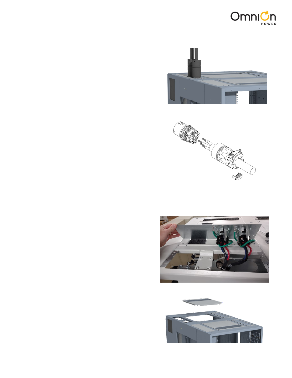
• Compression Connectors.
• U. S. or Canada installations – use Listed/Certied compression connectors to terminate Listed/Certied
eld – wire conductors.
• All installations – apply the appropriate connector to the correct size conductor as specied by the
connector manufacturer, using only the connector manufacturer’s recommended or approved tooling for
that connector.
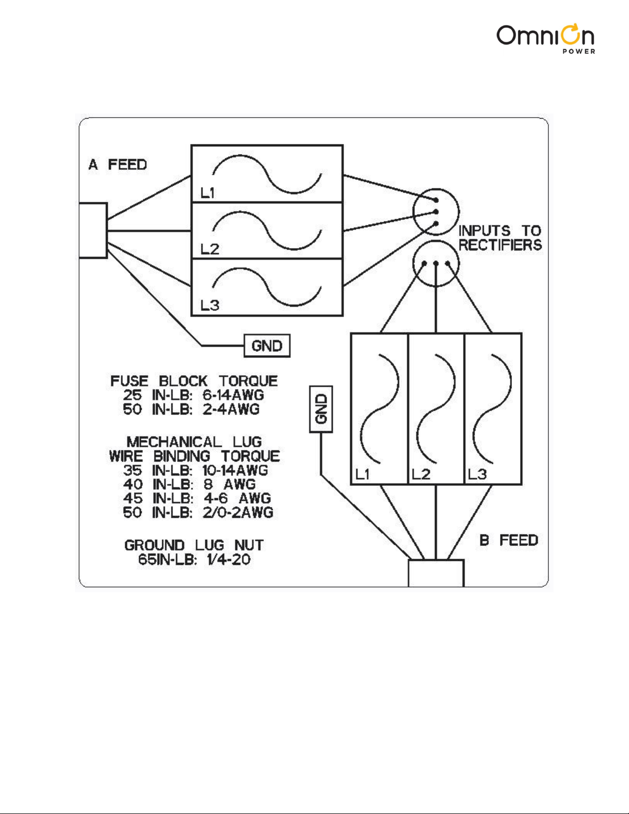
• Electrical Connection Securing: Torque to the values specied on labels or in the product documentation.
• Cable Dress – dress to avoid damage to the conductors and undue stress on the connections.
• Fuses
• Use only those specied in the equipment labeling Size as required by the National Electric Code (NEC)
and/or local codes.
• Safety Tested Limits – Refer to the equipment ratings to assure current does not exceed: Continuous Load
(List 1) – 80% of protector rating.
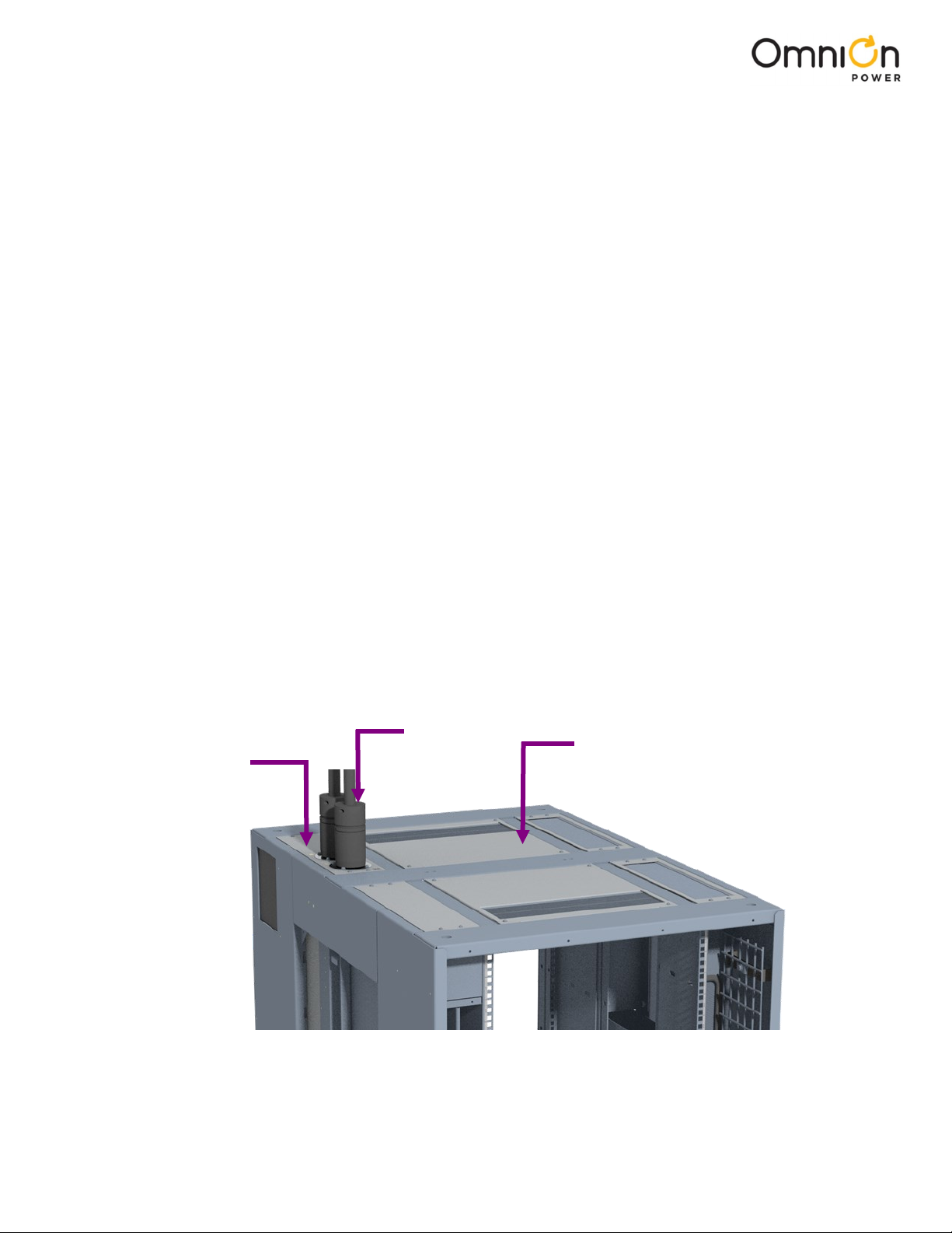
• AC input – Provide accessible devices to remove input power in an emergency.
• Grounding – Connect the AC input ground directly to chassis where marked. Connect chassis to main cabinet
ground bus bar. Note: Proper grounding of AC supply must be veried by qualied personnel.
• Do not place combustible material directly above or below equipment.
Consignes de sécurité importantes (French)
• N'installez pas cet équipement sur des surfaces combustibles.
• Règles et réglementations – Suivez toutes les règles et réglementations nationales et locales lors des connexions
sur le terrain.
• Connecteurs à compression
• Installations aux États-Unis ou au Canada - utilisez des connecteurs à compression homologués/certiés
pour terminer les conducteurs de l homologués/certiés.
• Toutes les installations - appliquez le connecteur approprié au conducteur de taille correcte tel que
spécié par le fabricant du connecteur, en utilisant uniquement l'outillage recommandé ou approuvé par
le fabricant du connecteur pour ce connecteur.
• Fixation de la connexion électrique : Serrez aux valeurs spéciées sur les étiquettes ou dans la documentation du
produit.
• Habillage de câble – Habillez-vous pour éviter d'endommager les conducteurs et de soumettre les connexions à
des contraintes excessives.
• Fusibles
• N'utilisez que ceux spéciés sur l'étiquette de l'équipement. Taille, comme requis par le National Electric
Code (NEC) et/ou les codes locaux.
• Limites de sécurité testées – Reportez-vous aux valeurs nominales de l'équipement pour vous assurer que
le courant ne dépasse pas : Charge continue (Liste 1) – 80 % de la valeur nominale du protecteur.
• Entrée CA – Fournir des appareils accessibles pour couper l'alimentation d'entrée en cas d'urgence.
• Mise à la terre – Connectez la terre de l'entrée CA directement au châssis à l'endroit marqué. Connectez le châssis
à la barre omnibus de mise à la terre de l'armoire principale. Remarque : La mise à la terre correcte de
l'alimentation CA doit être vériée par un personnel qualié.
• Ne placez pas de matériaux combustibles directement au-dessus ou en dessous de l'équipement.

Page 4
© 2023 OmniOn Power Inc. All rights reserved. Edge current limiter G390_QSG Rev. 2.1
Precauons
• Install, service, and operate equipment only by professional, skilled and qualied personnel who have the
necessary knowledge and practical experience with electrical equipment and who understand the hazards that
can arise when working on this type of equipment.
• Do not disconnect permanent bonding connections unless all power inputs are disconnected.
• Verify that equipment is properly safety earth grounded before connecting power. High leakage currents may be
possible.
• Exercise care and follow all safety warnings and practices when servicing this equipment. Hazardous energy and
voltages are present in the unit and on the interface cables and connectors that can shock or cause serious injury.
• Use safe lifting practices. The equipment is heavy. Lifting devices are recommended.
• Use the following precautions in addition to proper job training and safety procedures:
• Use only properly insulated tools.
• Remove all metallic objects (key chains, glasses, rings, watches, or other jewelry).
• Follow Lock Out Tag Out (LOTO) procedures: customer specied, site specic, or general as appropriate.
Disconnect all power input before servicing the equipment. Check for multiple power inputs.
• Wear safety glasses.
• Follow Personal Protective Equipment requirements: customer specied, site specic, or general as
appropriate.
• Test circuits before touching.
• Be aware of potential hazards before servicing equipment.
• Identify exposed hazardous electrical potentials on connectors, wiring, etc.
• Avoid contacting circuits when removing or replacing covers.
• Use a personal ESD strap when accessing or removing electronic components.
• Personnel with electronic medical devices need to be aware that proximity to DC power and distribution systems,
including batteries and cables, typically found in telecommunications utility rooms, can affect medical electronic
devices, such as pacemakers. Effects decrease with distance.

Page 5
© 2023 OmniOn Power Inc. All rights reserved. Edge current limiter G390_QSG Rev. 2.1
Précauons (French)
• Installez, entretenez et utilisez l'équipement uniquement par du personnel professionnel, compétent et qualié
qui possède les connaissances et l'expérience pratique nécessaires avec l'équipement électrique et qui comprend
les dangers qui peuvent survenir lors de travaux sur ce type d'équipement.
• Ne déconnectez pas les connexions de liaison permanentes à moins que toutes les entrées d'alimentation ne
soient déconnectées.
• Vériez que l'équipement est correctement mis à la terre de sécurité avant de brancher l'alimentation. Des
courants de fuite élevés peuvent être possibles.
• Soyez prudent et suivez tous les avertissements et pratiques de sécurité lors de l'entretien de cet équipement. Des
énergies et des tensions dangereuses sont présentes dans l'unité et sur les câbles d'interface et les connecteurs
qui peuvent provoquer des chocs ou des blessures graves.
• Utilisez des pratiques de levage sécuritaires. Le matériel est lourd. Les appareils de levage sont recommandés.
• Utilisez les précautions suivantes en plus de la formation professionnelle appropriée et des procédures de
sécurité :
• Utilisez uniquement des outils correctement isolés:
• Retirez tous les objets métalliques (porte-clés, lunettes, bagues, montres ou autres bijoux).
• Suivez les procédures LOTO (Lock Out Tag Out) : spéciées par le client, spéciques au site ou générales,
selon le cas.
Débranchez toutes les entrées d'alimentation avant de procéder à l'entretien de l'équipement. Vériez les
entrées d'alimentation multiples.
• Portez des lunettes de sécurité.
• Respectez les exigences relatives à l'équipement de protection individuelle : spéciées par le client,
spéciques au site ou générales, selon le cas.
• Testez les circuits avant de toucher.
• Soyez conscient des dangers potentiels avant de procéder à l'entretien de l'équipement.
• Identiez les potentiels électriques dangereux exposés sur les connecteurs, le câblage, etc.
• Éviter tout contact avec les circuits lors du retrait ou du remplacement des couvercles.
• Utilisez une sangle ESD personnelle lors de l'accès ou du retrait des composants électroniques.
• Le personnel équipé d'appareils médicaux électroniques doit être conscient que la proximité des systèmes
d'alimentation et de distribution CC, y compris les batteries et les câbles, que l'on trouve généralement dans les
locaux techniques de télécommunications, peut affecter les appareils électroniques médicaux, tels que les
stimulateurs cardiaques. Les effets diminuent avec la distance.

Page 6
© 2023 OmniOn Power Inc. All rights reserved. Edge current limiter G390_QSG Rev. 2.1
Safety
Read and follow all safety statements, warnings, and precautions in this manual before installing, maintaining or
repairing this equipment.
Equipment Idencaon
The product ID label of the EDGECABG390 model is shown below. It includes the product serial number and input -
output specications of the cabinet.
Customer Care
+1 877 546-3243
Sécurité (French)
Lisez et suivez toutes les consignes de sécurité, les avertissements et les précautions de ce manuel avant d'installer,
d'entretenir ou de réparer cet équipement.
Figure 1 Warning Label
Figure 2 Product ID Label Information

Page 7
© 2023 OmniOn Power Inc. All rights reserved. Edge current limiter G390_QSG Rev. 2.1
Wiring diagram
Figure 3 wiring diagram

Page 8
© 2023 OmniOn Power Inc. All rights reserved. Edge current limiter G390_QSG Rev. 2.1
Informaon – Tools Required
Regulations, standards, site engineering instructions etc. take precedence over these general installation instructions.
• Steel toe safety shoes
• Torque wrench - 0-65 in-lb (0-10 Nm) and 40 ft-lbs
• Volt Meter for Lock-Out Tag-Out procedures
Check for deliveries:
Make sure that the box contains the
• 8x #6-32 Screws (CC408578537)
• 6x 60A Fuses (4600482350P)
• 6x Fuse Covers (4600480552P)
• 9x #4-40 Nuts (CC408578388)
Cabinet Top
The top of the Edge cabinet is shown here. The relevant areas are noted:
1. AC input panel which contains two twist-n-lock AC input receptacles for AC input power.
2. Center back panel to be removed and replaced with Edge AC current limiter G390 assembly.
Two AC input
cords with
twist-n-lock
plugs
AC input panel
with two
twist-n-lock
receptacles
Center-Back Panel
Figure 4 Cabinet top
• Sockets - as needed for mounting hardware
• Screwdrivers - #2 pozi drive screwdriver. Flat and
Torx bit set with security pin

Page 9
© 2023 OmniOn Power Inc. All rights reserved. Edge current limiter G390_QSG Rev. 2.1
Step 1. Disassemble exisng AC connecons
Use "Turn off/Lock Out Tag Out".
1. Turn off AC power supplying the Edge cabinet.
2. Note which cord is “A” feed and which is “B” feed.
3. Unplug AC cords from the twist-n-lock input receptacles
at the top of the cabinet.
Step 2. Disassemble AC panel and central panel
1. Remove the 4 screws which attach the AC input
panel to top of the cabinet so that the panel can be
opened as shown.
2. Disconnect the black, blue and red wires from each of
the receptacles. Keep track of the wire which is
connected to “A” and “B” receptacles.
3. Remove the 4 screws on the back center panel and
then remove the panel.
Note: Both the AC input panel and the back center panel
will be discarded.
Figure 5 Disassemble AC connection
Figure 6 Twist-n-lock plug
Figure 7 AC panel removed
Figure 8 Central panel removed
4. Disconnect both AC cords/wires from each twist-n-lock
plug and keep cords for reassembly later.
Note: This process is written for a system that is not providing
active load support or that can be temporarily taken
down. If this system is live and cannot be taken down
for the installation duration period please contact
Technical Support to discuss alternatives.

Page 10
© 2023 OmniOn Power Inc. All rights reserved. Edge current limiter G390_QSG Rev. 2.1
Step 3. Assemble EDGECABG390 to cabinet
1. Assemble the base panel assembly to the top of the
cabinet using the 8 #6-32 screws provided.
Torque to 10in-lb. (Nm)
Note: The top cover must be disassembled from the base
panel assembly in order to have access to the
mounting holes. Keep track of nuts for reassembly
at step 3.
2. Pull the wires that were previously connected to the
twist-n-lock receptacles (Step 2, 2) through the two
grommeted holes in the base panel and terminate to
the fuse blocks. The fuse blocks are labeled A and B.
Attach the wires removed from the A receptacle to the
fuse block labeled A. Repeat for the B block. Each fuse
position is labeled L1, L2, or L3. Terminate red wire to
L1, black wire to L2, and blue wire to L3.
Torque to 25in-lb.
3. Reassemble the top cover using the 6 provided #4-40
nuts.
Torque to 5in-lb.
4. Strip the outer jacket of the AC feed cord (Step 1)
exposing a minimum of 6” of each individual wire. The
white wire should be cut ush with main cord outer
jacket.
5. Assemble the AC cords through the appropriate strain
relief (“A” or “B”) and then terminate the individual
wires to the fuse blocks. Each fuse position is labeled
L1, L2, L3. Terminate black wire to L1, red wire to L2,
and orange wire to L3. Torque to 25in-lb. Also, tie wires
to side wall of top cover to strain relief.
6. Terminate green ground wires to appropriate ground
lugs. Torque lug set screw to 45in-lb. Also tie wires to
side wall of top cover to strain relief.
Note: 2-hole compression lugs are also provided which
can be used instead of the single-hole mechanical
lug.
Figure 10 Wire connections
Figure 12 AC cord wiring
Figure 9 Panel assembly
Screws
Screws
Figure 11 Assembling top cover
Screws

Page 11
© 2023 OmniOn Power Inc. All rights reserved. Edge current limiter G390_QSG Rev. 2.1
Step 4. Final Assembly
1. Verify all fuses are fully assembled into each
position of the fuse blocks.
3. Connect ground wire provided in the G390 kit to
the ground lug located on the bottom of the base
panel assembly. Connect the other end of the
ground wire to the cabinet ground bus.
Torque lug set screw to 45in-lb.
Torque screw on ground bus to 65in-lb.
Note: 2-hole compression lugs are also provided
which can be used instead of the single-hole
mechanical lug.
2. Attach clear, removable panel to the top cover.
Torque to 10in-lb.
Figure 13 Fuse blocks
Ground wire
Figure 15 Cabinet grounding
Figure 14 Clear removable panel

Page 12
© 2023 OmniOn Power Inc. All rights reserved. Edge current limiter G390_QSG Rev. 2.1
Revision Date Description of the change
1.0 05-17-2023 Initial release
2.0 06-21-2023 Updated wiring diagram, Updated ordering
code of fuses in “Check for deliveries” section
2.1 11-28-2023 Updated as per OmniOn template
Change History (excludes grammar & claricaons)

Page 13
© 2023 OmniOn Power Inc. All rights reserved. Edge current limiter G390_QSG Rev. 2.1
OmniOn Power Inc.
601 Shiloh Rd.
Plano, TX USA
omnionpower.com
We reserve the right to make technical changes or
modify the contents of this document without prior
notice. OmniOn Power does not accept any responsibility
for errors or lack of information in this document and
makes no warranty with respect to and assumes no
liability as a result of any use of information in this
document.
We reserve all rights in this document and in the subject
matter and illustrations contained therein. Any
reproduction, disclosure to third parties or utilization of
its contents – in whole or in parts – is forbidden without
prior written consent of OmniOn Power. This document
does not convey license to any patent or any intellectual
property right. Copyright© 2023 OmniOn Power Inc. All
rights reserved.
This manual suits for next models
1
Table of contents
Other OmniOn Power Industrial Equipment manuals
Popular Industrial Equipment manuals by other brands

SCHUNK
SCHUNK DPZ 64 Assembly and operating manual

HIPERBARIC
HIPERBARIC 420 instruction manual

Hydac
Hydac IXU 1 Series Operating and maintenance instructions

PFlow Industries
PFlow Industries Mechanical VRC M Series owner's manual

Otto
Otto 750 Operation and maintenance manual

Siemens
Siemens 3200A operating instructions