OMCA SMF User manual

MANUALE D’USO E MANUTENZIONE
USE AND MAINTENANCE MANUAL
Smussatrice
Chamfering machine
OMCA mod. SMF
Art. 900
OMCA S.r.l
Via Curiel, 6 - 42025 - Cavriago (RE) - ITALY
Phone +39 0522 943502 / +39 0522 943503
Website: www.omcasrl.it - E-mail: [email protected]
2012
5a
Matricola
Serial number
Anno di fabbricazione
Year built
Edizione del manuale
Edition of the manual
Manuale redatto nel
Manual prepared in Giugno
June

0
INDICE INDEX
2OMCA S.r.l - Via Curiel, 6 - 42025 - Cavriago (RE) - ITALY
0. INDEX
1. INTRODUCTION
1.1 WARNINGS..................................................................... 3
2.
AREA OF APPLICATION AND TECHNICAL DATA
2.1 AREA OF APPLICATION.................................................. 4
2.2 TECHNICAL DATA .......................................................... 4
2.3 NOISE............................................................................ 4
2.4 VIBRATION..................................................................... 4
2.5 MAIN PARTS.................................................................. 5
3. TRANSPORT AND INSTALLATION
3.1 UNPACKAGE.................................................................. 6
3.2 ELECTRICAL INSTALLATION .......................................... 6
3.3 MACHINE HANDLING WITH PACKING ............................ 8
3.4 MACHINE HANDLING WITH TROLLEY............................ 9
3.5 MACHINE HANDLING WITHOUT TROLLEY ..................... 9
4. USE
4.1 MAIN CONTROLS .......................................................... 10
4.2 MACHINE SETTING WITH TROLLEY ............................... 13
4.3 MACHINE SETTING BENCH MODE ................................. 15
4.4 MACHINE SETTING WITHOUT TROLLEY ........................ 16
4.5 CHAMFERING ADJUSTMENT ......................................... 18
4.6 ANGLE ADJUSTMENT.................................................... 19
4.7 CUT DEPTH ................................................................... 19
5. MAINTENANCE AND ADJUSTMENT
5.1 INSERTS REPLACING .................................................... 21
5.2 CLEANING..................................................................... 23
5.3 DISPOSAL ..................................................................... 23
6. ATTACHMENTS
6.1 ELECTRICAL DIAGRAM.................................................. 25
6.2 SPARE PARTS LIST........................................................ 33
6.3 CUT SPEED AND DEPTH................................................ 47
0. INDICE
1. INTRODUZIONE
1.1 AVVERTENZA.................................................................. 3
2. CAMPO DI UTILIZZO E DATI TECNICI
2.1 CAMPO DI UTILIZZO ...................................................... 4
2.2 DATI TECNICI................................................................. 4
2.3 RUMOROSITA’ ............................................................... 4
2.4 VIBRAZIONI.................................................................... 4
2.5 COMPONENTI PRINCIPALI ............................................. 5
3. TRASPORTO E INSTALLAZIONE
3.1 DISIMBALLO.................................................................. 6
3.2 INSTALLAZIONE ELETTRICA .......................................... 6
3.3 MOVIMENTAZIONE MACCHINA CON IMBALLO ............... 8
3.4 MOVIMENTAZIONE MACCHINA CON CARRELLO ............ 9
3.5 MOVIMENTAZIONE MACCHINA SENZA CARRELLO......... 9
4. UTILIZZO
4.1 COMANDI PRINCIPALI ................................................... 10
4.2 SETTAGGIO MACCHINA MODALITA’ CON CARRELLO ..... 13
4.3 SETTAGGIO MACCHINA MODALITA’ DA BANCO ............. 15
4.4 SETTAGGIO MACCHINA SENZA CARRELLO.................... 16
4.5 REGOLAZIONE DELLO SMUSSO..................................... 18
4.6 VARIAZIONE DELL’ANGOLO............................................ 19
4.7 PROFONDITA’ DI PASSATA ............................................. 19
5. MANUTENZIONE E REGOLAZIONE
5.1 SOSTITUZIONE INSERTI................................................. 21
5.2 PULIZIA ......................................................................... 23
5.3 SMALTIMENTO .............................................................. 23
6. ALLEGATI
6.1 SCHEMA ELETTRICO..................................................... 25
6.2 ELENCO DEI RICAMBI.................................................... 33
6.3 VELOCITA’ E PROFONDITA’ DI PASSATA.......................... 47

1INTRODUZIONE INTRODUCTION
3
OMCA S.r.l - Via Curiel, 6 - 42025 - Cavriago (RE) - ITALY
1.1 AVVERTENZA
Scopo di questo manuale è la trasmissione delle informazioni neces-
sarie all’uso competente e sicuro della smussatrice OMCA mod. SMF.
Per un corretto rapporto col prodotto, è necessario garantire leggi-
bilità e conservazione del manuale. In caso di deterioramento, o più
semplicemente per ragioni di approfondimento tecnico e operativo,
consultare direttamente il Costruttore.
Prima di operare sulla macchina, accertarsi sempre ed in via preven-
tiva di avere compreso il contenuto del manuale.
Il mancato rispetto delle prescrizioni in esso contenute esimono il Co-
struttore da qualsiasi responsabilità. Qualora fossero necessari ap-
profondimenti, rivolgersi direttamente al Costruttore.
E' tassativamente vietato manomettere apparecchiature e/o dispositivi
di sicurezza.
Qualsiasi intervento di manutenzione va effettuato da personale spe-
cializzato.
L’utilizzo di questa macchina è vietato per operazioni non indicate spe-
cificatamente in questo manuale.
Per qualsiasi informazione particolare inerente l’uso della macchina, la
manutenzione, i pezzi di ricambio, ecc., occorre rivolgersi direttamen-
te al costruttore, i cui dati sono indicati nella copertina del manuale e
sulla targa di identificazione riportata fronte della macchina (Fig. 1.1).
1.1 WARNINGS
The purpose of this handbook is to explain all the necessary information
for a safe and a right use of the chamfering machine OMCA mod. SMF.
It is very important to keep readable and in a good state of conser-
vation this handbook for a correct feeling with the product. In case of
somehow damage or if you need more technical information, please
contact the Manufacturer directly.
Before operate with the machine, be sure that you had learn all the
information of this handbook.
Failure to follow the instructions on this manual releases the manufac-
turer from any liability. For any further information please contact the
Manufacturer directly.
It is strictly forbidden to tamper with the equipment and/or safety de-
vices.
Only specialized personal can execute all the maintenance operation.
A different use of the machine that is not authorized in this handbook
is strictly forbidden.
For any further information about the use of the machine, the main-
tenance, the spare parts, etc.. you might contact the Manufacturer
using the specifications reported on the label in front of the machine,
or using the data reported on the cover of this handbook (Pic. 1.1).
CAREFULLY READ THE INFORMATION EXPLAINED IN THIS
HANDBOOK BEFORE THE INSTALLATION AND THE USE OF THE
MACHINE. FOLLOW THE INSTRUCTIONS WITH CARE!
LEGGERE ATTENTAMENTE LE INFORMAZIONI CONTENUTE NEL
PRESENTE MANUALE PRIMA DELL’INSTALLAZIONE E DELL’UTI-
LIZZO DELLA MACCHINA ED ATTENERSI SCRUPOLOSAMEN-
TE ALLE INDICAZIONI IN ESSO CONTENUTE
1.1
1. INTRODUZIONE 1. INTRODUCTION

2
4OMCA S.r.l - Via Curiel, 6 - 42025 - Cavriago (RE) - ITALY
CAMPO DI UTILIZZO
E DATI TECNICI AREA OF APPLICATION
AND TECHNICAL DATA
Potenza motore fresa 4 Kw
Potenza motore avanzamento 0,6 Kw
Regolazione smusso 5-30 mm (diagonale 50mm)
Diametro fresa 63 mm (Z5)
Inclinazione fresa 15° - 60°
Peso 185 Kg
Altezza 1600 mm
Larghezza 600 mm
Profondità 600 mm
Regolazione altezza 200 mm
Velocità di avanzamento 0 - 1 mt/min
Milling cutter motor power 4 Kw
Feed motor power 0,6 Kw
Chamfer adjustment 5-30 mm (diagonal 50mm)
Milling cutter diameter 63 mm (Z5)
Chamfer angle 15° - 60°
Weight 185 Kg
Height 1600 mm
Width 600 mm
Depth 600 mm
Height adjustment 200 mm
Feed speed 0 - 1 mt/min
2. CAMPO DI UTILIZZO E DATI TECNICI
2.1 CAMPO DI UTILIZZO
La smussatrice SMF (Fig. 2.1) è una macchina che si può utilizzare
in tre modi:
1-montata sul suo carrello, per effettuare smussi su lamiere di medie e
grandi dimensioni; 2-modalità da banco, per eseguire smussi su pez-
zi maneggiabili manualmente; 3-“sospesa” senza carrello, ove non sia
possibile lavorare ad altezze standard.
La SMF serve per effettuare smussature su qualsiasi materiale di tipo
ferroso (in particolare acciaio inox, acciaio, leghe leggere e ghisa).
IT IS FORBIDDEN TO USE THE MACHINE FOR PROCESSING
OTHER THAN THOSE SPECIFIED IN THIS MANUAL. FOR
EXAMPLE IT MAY NOT WORK ON WOOD.
E’ VIETATO USARE LA MACCHINA PER LAVORAZIONI DIVER-
SE DA QUELLE INDICATE NEL PRESENTE MANUALE:
AD ESEMPIO È VIETATO LAVORARE IL LEGNO.
WHEN THE MACHINE IS USED WITHOUT ITS TROLLEY, IS ABSO-
LUTELY IMPORTANT TO MOVE IT WITH AN ADEQUATE SUPPORT,
AND THE OPERATOR HAS TO KEEP THE MACHINE WITH BOTH
HANDS ON THE HANDLE DURING ALL THE OPERATION.
NELL’UTILIZZO SENZA IL CARRELLO, È ASSOLUTAMENTE NE-
CESSARIO CHE LA MACCHINA VENGA MOVIMENTATA CON UN
ADEGUATO SUPPORTO E CHE L’OPERATORE AFFERRI CON EN-
TRAMBE LE MANI LE APPOSITE IMPUGNATURE DURANTE
L’UTILIZZO IN SUDDETTA CONFIGURAZIONE.
2.2 DATI TENICI
2.3 RUMOROSITÀ
THE SOUND PRESSURE LEVEL CAN IN SOME CASES AND
UNDER CERTAIN OPERATING CONDITIONS, EXCEED THE 85
DBA. IN ANY CASE THE USE OF THE MACHINE REQUIRES
EAR PROTECTION.
IL LIVELLO DI PRESSIONE ACUSTICA IN ALCUNI CASI E CON-
DIZIONI OPERATIVE, PUÒ SUPERARE GLI 85 DBA. IN OGNI
CASO L’USO DELLA MACCHINA RICHIEDE LE PROTEZIONI
AURICOLARI.
2.3 NOISE
2. AREA OF APPLICATION AND TECHNICAL DATA
2.1 AREA OF APPLICATION
The SMF (Pic. 2.1) chamfering machine can be used in three ways:
1-mounted on its trolley, for chamfering on medium and big size
sheets; 2-Bench version, for chamfering on work-pieces that can be
handled manually; 3-“hanged” version, without its trolley, when it is
not possible to work at standard heights.
The SMF is useful for chamfer every ferrous materials (especially ste-
el, stainless steel, light alloys and cast iron).
2.2 TECHNICAL DATA
2.4 VIBRAZIONI
Il valore dell’accelerazione cui sono esposte le membra superiori
dell’operatore durante l’uso della macchina non supera i 2,5 m/s².
2.4 VIBRATION
The value of the acceleration which submits the operator’s upper
limbs during the use of the machine does not exceed 2,5 m/s.

2
5
OMCA S.r.l - Via Curiel, 6 - 42025 - Cavriago (RE) - ITALY
CAMPO DI UTILIZZO
E DATI TECNICI AREA OF APPLICATION
AND TECHNICAL DATA
2.5 COMPONENTI PRINCIPALI 2.5 MAIN PARTS
2.1
1Fresa
2Ruote di avanzamento
3Quadro di comando
4Impugnatura
5Manopola regolazione smusso
6Motore principale
7Basamento con ruote
8Manopola regolazione velocità avanzamento
9Leva bloccaggio regolazione smusso
10 Volantino regolazione altezza
11 Volantino regolazione altezza rulli trascinatori
12 Scatola comando selettore automatico/manuale
13 Motoriduttore avanzamento
1Milling-cutter
2Feed wheels
3Control board
4Handle
5Chamfer adjustment hand-wheel
6Main motor
7Wheeled base
8Feed speed adjustment hand-wheel
9Chamfer adjustment locking lever
10 Height adjustment hand-wheel
11 Height adjustment feed wheels
12 Control box switch auto/manual
13 Feed gearbox
3
5
6
8
4
13
11
9
10
7
2
1
12

3
TRASPORTO E
INSTALLAZIONE TRANSPORT AND
INSTALLATION
6OMCA S.r.l - Via Curiel, 6 - 42025 - Cavriago (RE) - ITALY
3.1 DISIMBALLO
La macchina viene fornita imballata assieme al presente manuale di
istruzioni ed alle varie chiavi in dotazione.
Effettuare il disimballo della macchina togliendo i sigilli, e facendo at-
tenzione a non danneggiare le sue parti.
Al termine di questa operazione verificare l’integrità della macchina: se
c’è qualche problema, contattare immediatamente il rivenditore comu-
nicando i dati della macchina.
3.2 INSTALLAZIONE ELETTRICA
La macchina è fornita con cavo di alimentazione:
3 fasi + neutro + , con sezione da 2,5 mm.
Prima dell’allacciamento alla tensione di rete, collegare il cavo di ali-
mentazione ad una spina di tipo industriale conforme alla norme CEI
EN 60309-1 con 3 fasi + neutro + , tensione di 400 V, portata di
16 A, e grado di protezione almeno IP44.
Fare comunque riferimento allo schema elettrico.
Prima di collegare la macchina alla presa elettrica, accertarsi che la
linea abbia una sezione adeguata alla corrente di impiego della mac-
china e che a monte sia presente un dispositivo di protezione contro
i sovraccarichi.
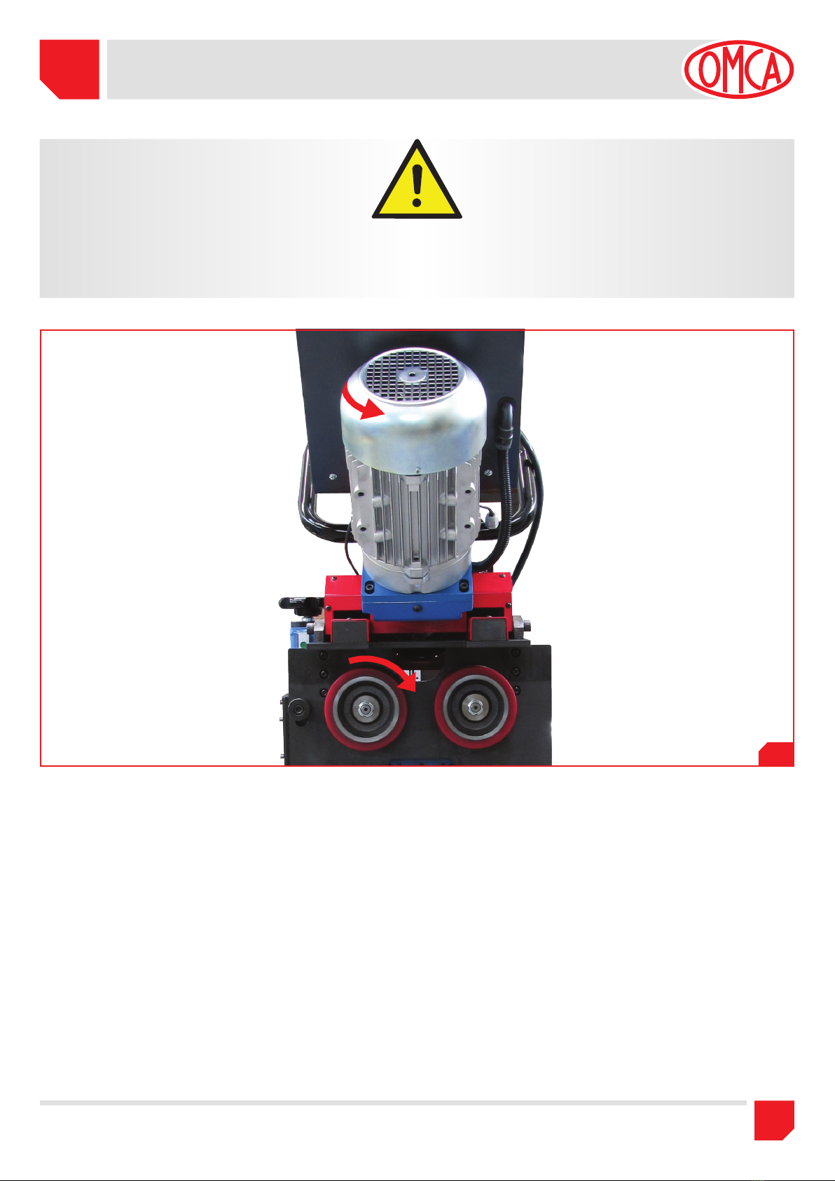
Dopo aver collegato il cavo elettrico alla spina controllare il corretto
senso di rotazione della fresa (come indicato in Fig. 3.1) facendo
girare la macchina a vuoto.
Nel caso di rotazione errata invertire le due fasi nel collegamento della
spina.
L’impianto di terra ed il dispositivo di interruzione a monte della mac-
china devono essere coordinati in modo da assicurare la protezione
contro i contatti indiretti secondo la norme CEI 64-8.
Accertarsi che tale protezione sia assicurata mediante un dispositivo
differenziale ad elevata sensibilità (30 mA).
3.1 UNPACKAGE
The machine is supplied packed complete with this handbook and
different wrenches.
Unpack the machine by removing the seals, taking care not to break
any parts.
When the machine is duly unpacked, check that all its part are in
perfect condition. If any anomalous conditions is noticed, contact im-
mediately your Seller by telling the data of the machine.
3.2 ELECTRICAL INSTALLATION
The machine is supplied with power cable:
3 Phase + Neutral + 2,5mm. cross section area.
Before connecting to the mains voltage, connect to the power cable
to an industrial plug; in compliance with CEI EN 60309-1 Standard
with 3 Phase + Neutral + , 400 V, 16 Amp, protection class at
least IP44.
Please refer anyway to the electrical diagram.
Before connecting the machine to the mains voltage, make sure that:
the line has suitable square section for the current absorbed by the
machine and that a proper protection device to prevent overloads is
duly installed.
After connecting the power cable to the plug, make sure that the mil-
ling cutter turns in the right direction (as shown in Pic. 3.1) by running
the machine empty.
In case of incorrect rotation reverse the two phases of the plug.
The earthing system and the switching device located above the ma-
chine must be set to ensure protection against indirect contacts, ac-
cording to CEI 64-8 Standards.
Make sure that this protection is duly assured by an adequate high
sensivity differential device (30 mA).
ATTENTION: ONLY SPECIALIZED PERSONAL CAN EXECUTE THE
OPERATIONS OF HANDLING AND INSTALLATION OF THE MA-
CHINE, RESPECTING ALL THE SAFETY AND HEALTH REGULA-
TIONS IN FORCE.
ATTENZIONE: LE OPERAZIONI DI MOVIMENTAZIONE E DI INSTAL-
LAZIONE DELLA MACCHINA DEVONO ESSERE EFFETTUATE DA
PERSONALE SPECIALIZZATO, CHE DEVE PROCEDERE NEL PIENO
RISPETTO DELLE VIGENTI NORME DI SICUREZZA E SALUTE.
3. TRANSPORT AND INSTALLATION3. TRASPORTO E INSTALLAZIONE

3TRASPORTO E
INSTALLAZIONE TRANSPORT AND
INSTALLATION
7
OMCA S.r.l - Via Curiel, 6 - 42025 - Cavriago (RE) - ITALY
3.1
ATTENTION:
AFTER CONNECTING THE MACHINE’S PLUG TO THE SOCKET
OF THE PLANT, MAKE SURE THAT:
1) The cable will not hamper and will not cause a stumbling risk.
2) The cable does not pass on the floor in any area of truck transit or
other vehicles that may damage it.
ATTENZIONE:
DOPO AVER COLLEGATO LA SPINA DELLA MACCHINA ALLA PRE-
SA DELLO STABILIMENTO, ACCERTARSI CHE:
1) Il filo non sia di intralcio e non causi un rischio di inciampo.
2) Il filo non passi sul pavimento in una zona di transito di carrelli
elevatori o altri mezzi che lo possano deteriorare.

3
TRASPORTO E
INSTALLAZIONE TRANSPORT AND
INSTALLATION
8OMCA S.r.l - Via Curiel, 6 - 42025 - Cavriago (RE) - ITALY
3.2
3.3 MOVIMENTAZIONE MACCHINA CON IMBALLO
La movimentazione della macchina imballata deve essere effettuata
mediante carrello elevatore o altro sistema meccanico avente suffi-
ciente resistenza (la macchina pesa circa 210 Kg).
Il disimballo e la movimentazione della macchina deve essere ef-
fettuata con attenzione secondo le modalità descritte di seguito:
1) Rimuovere le regge e sfilare l’imballo in cartone, togliere le regge
interne che ancorano la macchina al basamento in legno;
2) Agganciare il dispositivo di sollevamento al golfare come indicato
in (Fig. 3.2);
3.3 MACHINE HANDLING WITH PACKING
The machine handling with its package must be done with a lift truck
or other mechanical system having sufficient resistance (the weight
of machine is about 210 Kg).
The unpackaged and the handling of the machine must be done
paying attention to the following instructions:
1) Remove the locking straps and slip the carton box off, remove the
internal straps that anchor the machine on the wooden base;
2) Hook the lifting device at the eyebolt as showed on (Pic. 3.2);
3)
Dopo essersi accertati che il gancio sia ben chiuso, sollevare leg-
germente il carico e verificare che la macchina sia ben bilanciata;
4) Procedendo con cautela e senza strappi o movimenti bruschi,
portare la macchina nel luogo di destinazione;
5) Sganciare la macchina dal dispositivo di sollevamento dopo che ci
si è accertati che la macchina sia stabilmente posizionata al punto
di destinazione.
3) After making sure that the hook is well locked, lift slightly and
verify that the machine is well balanced;
4) Proceed with caution and without jerks or sudden movements
bring the machine at the working area;
5) Make sure that the machine is in a steady position and so unhook
the machine from the lifting device;
ATTENTION:
NEVER FORSAKE THE SUSPENDED LOAD DURING ITS MOVE-
MENT !
ATTENZIONE:
NON ABBANDONARE MAI IL CARICO SOSPESO DURANTE GLI SPO-
STAMENTI !

3TRASPORTO E
INSTALLAZIONE TRANSPORT AND
INSTALLATION
9
OMCA S.r.l - Via Curiel, 6 - 42025 - Cavriago (RE) - ITALY
3.4 MOVIMENTAZIONE MACCHINA CON CARRELLO
La macchina nasce con il suo carrello ed è preferibile l’utilizzo in que-
sta configurazione.
Essa può muoversi agevolmente su una pavimentazione regolare nor-
malmente esistente nelle officine, grazie alle ruote girevoli.
E’ possibile posizionarla nel suo sito di utilizzo semplicemente spin-
gendola dove desiderato.
Solo qualora la pavimentazione risultasse eccessivamente irregolare
rendendo impossibile la rotazione delle ruote, è necessario l’utilizzo di
un dispositivo di sollevamento (Fig.3.2).
3.4 MACHINE HANDLING WITH TROLLEY
The machine has been designed with its trolley; and it is preferable to
use in this configuration.
The machine can easily move on a regular floor normally present in
the workshop, thanks to swivel wheels.
It’s possible to move the machine by pushing it wherever you desired.
Only in case of irregular floor, making impossible the wheels rotation,
requires the use of a lifting device (Pic.3.2).
3.5 MOVIMENTAZIONE MACCHINA SENZA CARRELLO
La macchina priva del suo basamento deve essere aggangiata all’appo-
sito golfare e movimentata con un impianto di sollevamento.
3.5 MACHINE HANDLING WITHOUT TROLLEY
The machine without its trolley must be hooked to the relevant eyebolt
and moved with a lifting device.
3.3

4
UTILIZZO USE
10 OMCA S.r.l - Via Curiel, 6 - 42025 - Cavriago (RE) - ITALY
DURANTE L’USO DELLA MACCHINA DEVONO ESSERE INDOSSATE
LE SEGUENTI PROTEZIONI, PER LA SICUREZZA DELL’OPERATORE:
FOR OPERATOR’S SAFETY, DURING THE USE OF THE MACHINE, IT IS
NECESSARY TO WEAR THE PROTECTIONS AS BELOW:
Occhiali
Glasses Cuffie
Acustic earmuffs Guanti
Gloves Scarpe antinfortunistiche
accident-prevention shoes
La smussatrice SMF (Fig. 2.1) è una macchina che si può utilizzare
in tre modi:
1. montata sul suo carrello, per effettuare smussi su lamiere di medie
e grandi dimensioni,
2. modalità da banco, per eseguire smussi su pezzi maneggiabili ma-
nualmente
3. “sospesa” senza carrello, ove non sia possibile lavorare ad altezze
standard
Le tre modalità permettono una flessibilità di utilizzo della macchi-
na. La versione con carrello permette la lavorazione di lamiere medio
grandi, smussandone automaticamente tutta la lunghezza.
La versione da banco è idonea per i pezzi maneggiabili manualmente
per smussi di piccole dimensioni. Il pezzo verrà inserito nella macchi-
na sulle ruote di trascinamento
La versione “sospesa” è possibile utilizzarla laddove il basamento ri-
sulti d’ingombro durante la lavorazione.
4.1 COMANDI PRINCIPALI (
Fig.4.1 Pag.12)
A- Pulsante di emergenza: E’ il pulsante “a fungo” rosso la cui
funzione è quella di comandare, quando premuto, l’arresto di
emergenza della macchina. Va premuto in tutti i casi di pericolo o
comunque nel caso in cui ci sia un’anomalia che può portare ad
una situazione di rischio. Il riarmo può essere fatto semplicemente
ruotando il pulsante nel senso indicato dalle frecce (orario).
ATTENTION:
THE EMERGENCY BUTTON IS A SAFETY DEVICE, FOR THIS RE-
ASON IT SHOULD NOT BE DEACTIVATE, OR TAMPERED, OR
HIDDEN IN ANYWAY.
ATTENZIONE:
IL PULSANTE DI EMERGENZA È UN DISPOSITIVO DI SICUREZZA E
PERTANTO NON DEVE ESSERE DISABILITATO, MANOMESSO, O
COPERTO IN ALCUN MODO.
4. UTILIZZO 4. USE
Chamfer machine SMF (Pic. 2.1) can be used in three ways;
1. Mounted on its trolley, for chamfering on medium and big size
sheets;
2. Bench version, for chamfering on work-pieces that can be handled
manually;
3. “hanged” version, without its trolley, when it is not possible to
work at standard heights.
The three versions allow a machine use flexibility. The version with
trolley allows to work on medium/big size sheets, chamfering auto-
matically the complete length.
The bench version is suitable work-pieces, to be handled manually,
for small chamfers. The work-piece will be inserted into the machine
on the feeding wheels.
The “hanging version” is suitable when the base causes an obstacle
during the working process.
4.1 MAIN CONTROLS (
Pic.4.1 Page 12)
A- Emergency button: It is the red mushroom button, its function is
to control, when it pressed, the emergency stop of the machine.
You must press it in every case of danger or every time there’s any
anomalous situation.
The reset can be done simply by turning the button in the direction
indicated by arrows (clockwise).
ATTENTION:
IT IS FORBIDDEN TO USE THE MACHINE WITHOUT THE INSTALLED
PROTECTION
ATTENZIONE:
E’ VIETATO UTILIZZARE LA MACCHINA SENZA LE PROTEZIONI IN-
STALLATE.

4UTILIZZO USE
11
OMCA S.r.l - Via Curiel, 6 - 42025 - Cavriago (RE) - ITALY
B- Manopola di regolazione profondità di smusso: Ruotandola si
regola la profondità di smusso tra 5 e 30 mm.
C- Interruttore principale: Permette di sezionare la macchina dalla
alimentazione elettrica esterna.
D- Spia scatto termica: Si accende quando c’è un sovraccarico al
motore. Quando si accende occorre dapprima rimuovere la causa
che ha portato al sovraccarico e, successivamente, riarmare la
termica all’interno del quadro elettrico premendo sul pulsante nero
del salvamotore che è intervenuto, posizionandolo su ON (I) come
indicato in (Fig.4.1 Pos. 1).
E- Pulsante di start: Permette di accendere la macchina. Va premuto
dopo aver ruotato su ON (I) l’interruttore principale, oppure dopo
aver riarmato il pulsante di emergenza.
F- Spia “tensione”: La spia è accesa quando la macchina è connes-
sa all’alimentazione elettrica esterna e quando l’interruttore princi-
pale è su ON (I).
G-
Pulsanti di lavorazione bimanuali: Devono essere premuti contem-
poraneamente per far avanzare la macchina e, al tempo stesso, per
far ruotare la fresa. Azionando questi pulsanti si fa partire dapprima la
fresa e, dopo alcuni istanti (per ragioni di sicurezza), l’avanzamento.
H- Blocco fresa: Deve essere tenuto premuto (per bloccare la fre-
sa) quando vengono sostituiti gli inserti. E’ assolutamente vietato
premerlo mentre la macchina è accesa.
I- Leva sblocco regolazione smusso: Deve essere allentata solo
quando si deve modificare la dimensione dello smusso, quando
la macchina lavora deve essere sempre bloccata.
L- Pulsante rosso di stop: Serve per arrestare la macchina, premen-
dolo si ferma prima l’avanzamento e dopo pochi secondi la rota-
zione della fresa.
M-Volantino regolazione altezza: Serve per allineare in altezza la
macchina con la lamiera, quando si lavora in modalità da banco.
Ruotando in senso orario si alza la macchina, mentre si abbassa
ruotando in senso antiorario.
L’escursione permessa è di 200 mm in verticale.
N- Cavo di alimentazione: Serve per alimentare la macchina ed è
importante che venga protetto da urti e da pesi che possano dan-
neggiarne il funzionamento.
O- Manopola regolazione velocità di avanzamento: Tale comando
serve per regolare la velocità di avanzamento sulla base dei vari
materiali da lavorare e della dimensione dello smusso, per garan-
tire un ottimo grado di finitura.
La velocità di avanzamento può variare da 0 a 1 m/min.
B- Handle for chamfer depth adjustment hand-wheel: it is adjusted
by turning the depths between 5 - 30 mm.
C- Main switch:it allows the cut-out of the machine from the external
current supply.
D- Thermal light release:It switches on when the motor is overloa-
ded the thermal pilot switched on. When it happens you have to
remove the cause of the problem, and then restart the thermal
inside the control board by pushing the black button of the mo-
tor protection. By turning on the ON (I) position as showed on
(Pic.4.1 Pos. 1).
E- Start button:it makes the machine start. Push it after rotating the
main switch on the ON (I), or after reset the emergency button.
F- Light “voltage”:
The light is on when the machine is connected to
the external power supply and also when the main switch is ON (I).
G-
Bimanual processing buttons:they must be pushed simultaneously
to let the machine run and at the same time to let the cutter rotate.
With these buttons you start at first the milling-cutter and after few
seconds the feed.(for safety reasons).
H- Milling-cutter lock:it must be held down (to lock the milling-cut-
ter) whenever the inserts are replaced. It is absolutely forbidden
to push it when the machine is operating.
I - Chamfering adjustment release lever:it must be loosen only
when you have to change the chamfer depth. When the machine
is working the lever must always be locked.
L- Red stop button: It allows to stop the machine, by pushing it, the
feed stops firstly and, few seconds later, the milling-cutter rota-
tion.
M-Height adjustment handwheel: It is for aligning the height of the
machine with the sheet, when works in bench mode.
Turning clockwise the machine moves up, turning counterclockwi-
se it moves down.
The range permitted is 200 mm vertically.
N- Power cable:it supplies power to the machines, for this reason
you must pay attention and protect it from bumps that could da-
mage it.
O- Feed speed adjustment handwheel:it is used for the adjustment
of feed speed in according to the various material and the chamfer
entity, in order to grant an excellent finishing.
The feed speed can vary from 0 to 1m./min.

4
UTILIZZO USE
12 OMCA S.r.l - Via Curiel, 6 - 42025 - Cavriago (RE) - ITALY
4.1
C
O
A
F
D
L
E
N
M
I
G
H
B
1

4UTILIZZO USE
13
OMCA S.r.l - Via Curiel, 6 - 42025 - Cavriago (RE) - ITALY
1) Agire sul volantino di regolazione altezza, posizionato sul carrel-
lo (Fig.2.1 pos.10) in modo da posizionare i rulli di scorrimento
(Fig.4.2 pos.A) sul pezzo.
2) Abbassare le ruote di trascinamento (Fig.2.1 pos.2) mediante il
volantino (Fig.2 pos.11).
3) Posizionare il pezzo da lavorare in corrispondenza della prima ruo-
ta trainante come indicato in (Fig.4.2).
IMPORTANTE !!
la fresa non deve essere a contatto con la lamiera.
Inoltre fare attenzione che il pezzo sia ben aderente alle squadre
di posizionamento per una corretta e uniforme smussatura lungo
tutto il bordo.
4) Ruotare il volantino sotto alla macchina (Fig.2.1 pos.11) per ser-
rare la prima ruota di trascinamento contro il pezzo da lavorare.
Raggiunto il contatto, eseguire un’altro giro completo del vo-
lantino.
5) Regolare la profondità di smusso come indicato nel capitolo 4.5.
6) Premere il pulsante di marcia (Fig.4.1 pos.E) e ruotare lentamente
il potenziometro di regolazione velocità di avanzamento (Fig.4.1
pos.O) fino alla posizione di 0.3 (m/min).
Tenendo le mani ben salde sulla maniglia, accompagnare la
macchina durante l’inizio della lavorazione, (fino a quando il
pezzo non sale sulla seconda ruota di trascinamento).
7) In base alla dimensione dello smusso e del tipo di materiale è
possibile aumentare la velocità di avanzamento.
8) Alla fine della lavorazione, prima che il pezzo scenda da una ruota
di trascinamento diminuire la velocità di avanzamento fino alla po-
sizione di 0.3 (m/min).
Tenendo le mani ben salde sulla maniglia, accompagnare la
macchina durante la fine della lavorazione.
9) Per fermare la macchina premere il pulsante rosso di stop (Fig.4.1
Pos.L) del quadro generale.
1) Act on the height adjustment hand-wheel, situated on the trolley
(Pic.2.1 pos.10) to position the sliding rollers (Pic.4.2 pos.A) on
the piece.
2) Lower the feed wheels (Pic.2.1 pos.2) by the hand-wheel (Pic.2
pos.11).
3) Position the work piece on the first feed wheel as indicated on
(Pic.4.2).
IMPORTANT !!
The cutter must not be in contact with the sheet.
Moreover, pay attention that the piece is well fitted to the positio-
ning sets for a correct and uniform chamfering on the whole edge.
4) Turn the hand-wheel under the machine (Pic.2.1 pos.11) to tighten
the first feed wheel against the work-piece.
Reached the contact perform another full turn of the hand-whe-
el.
5) Adjust the chamfer depth as indicated on chapter 4.5.
6) Push the start button (Pic.4.1 pos.E) and turn slowly the potentio-
meter of feed speed regulation (Pic.4.1 pos.O) until the position of
0.3 (m/min).
By keeping the hands steady on the handle, drive the machine
during the working beginn (until the piece comes up on the se-
cond feed wheel).
7) Based on of the chamfer dimension and the type of material it is
possible to increase the feed speed.
8) At the end of working, before the piece goes down from a feed
wheel, reduce the feed speed until the position of 0.3 (m/min).
Keeping the hands steady on the handle, drive the machine un-
til the working end.
9) To stop the machine push the red button on the control board
(Pic.4.1 Pos.L).
ATTENTION:
BEFORE BEGINNING TO USE THE MACHINE, BE SURE THAT THE
WORK PIECE IS STABLE ANCHORED AND CORRECTLY POSITIO-
NED.
ATTENZIONE:
PRIMA DI INIZIARE AD UTILIZZARE LA MACCHINA, ASSICURARSI
CHE IL IL PEZZO DA LAVORARE SIA STABILE, ANCORATO E COR-
RETTAMENTE POSIZIONATO.
4.2 SETTAGGIO MACCHINA MODALITA’ CON CARRELLO 4.2 MACHINE SETTING WITH TROLLEY

4
UTILIZZO USE
14 OMCA S.r.l - Via Curiel, 6 - 42025 - Cavriago (RE) - ITALY
NOTE:
THANKS TO THE TROLLEY, THE MACHINE CAN WORK WHERE THE
FLOOR IS NOT REGULAR THAT SHOWS MODERATE UNEVENNESS
IN THIS CASE, DURING THE JOB, IT IS POSSIBLE ACTING ON THE
HEIGHT ADJUSTMENT HAND-WHEEL (PIC.2.1 POS.10), LIFTING UP
THE TROLLEY WHEELS.
IN THIS WAY THE MACHINE WILL CONTINUE RUNNING ON THE
WORKPIECE, AVOIDING THE WHEELS TOUCHING THE FLOOR.
NEAR THE END OF WORKING PROCESS, BRING THE WHEELS IN
CONTACT WITH THE FLOOR.
NOTA:
LA MACCHINA COL CARRELLO PUÒ LAVORARE ANCHE LADDOVE LA
PAVIMENTAZIONE NON È PERFETTAMENTE REGOLARE E PRESENTA
SCONNESSIONI NON ECCESSIVE O AVVALLAMENTI MODESTI. IN TAL
CASO È POSSIBILE DURANTE LA FASE DI LAVORAZIONE, AGIRE SUL
VOLATINO REGOLAZIONE ALTEZZA DA TERRA (Fig.2.1 Pos.10) SOLLE-
VANDO LE RUOTE DEL CARRELLO.
CON QUESTA MANOVRA LA MACCHINA CONTINUERÀ A LAVORARE,
AVANZANDO SUL PEZZO, SENZA CHE LE RUOTE DEL CARRELLO TOC-
CHINO TERRA.
IN PROSSIMITÀ DELLA FINE DELLA LAVORAZIONE RIPORTARE LE RUO-
TE A CONTATTO COL SUOLO.
4.2
A

4UTILIZZO USE
15
OMCA S.r.l - Via Curiel, 6 - 42025 - Cavriago (RE) - ITALY
4.3 SETTAGGIO MACCHINA MODALITA’ DA BANCO 4.3 MACHINE SETTING BENCH MODE
1) Installare il supporto da banco (in dotazione) (Fig.4.3 pos.A).
2) Abbassare le ruote di trascinamento (Fig.2.1 pos.2) mediante il
volantino (Fig.2.1 pos.11).
3) Posizionare il pezzo da lavorare in corrispondenza della prima ruo-
ta trainante come indicato in (Fig.4.2).
IMPORTANTE !! la fresa non deve essere a contatto con la lamiera.
Inoltre fare attenzione che il pezzo sia ben aderente alle squadre di posi-
zionamento per una corretta e uniforme smussatura lungo tutto il bordo.
4) Ruotare il volantino sotto alla macchina (Fig.2.1 pos.11) per ser-
rare la prima ruota di trascinamento contro il pezzo da lavorare.
Raggiunto il contatto, eseguire un’altro giro completo del volantino.
5) Regolare la profondità di smusso come indicato nel capitolo 4.5.
6) Premere il pulsante di marcia (Fig.4.1 pos.E) e ruotare lentamente
il potenziometro che regola la velocità di avanzamento (Fig.4.1
pos.O) fino alla posizione di 0.3 (m/min).
7) In base alla dimensione dello smusso e del tipo di materiale è
possibile aumentare la velocità di avanzamento.
8) Alla fine della lavorazione, prima che il pezzo scenda da una ruota
di trascinamento diminuire la velocità di avanzamento fino alla po-
sizione di 0.3 (m/min).
9) Per fermare la macchina premere il pulsante rosso di stop (Fig.4.1
Pos.L) del quadro generale.
1) Install the bench support (standard equipment) (Pic.4.3 pos.A).
2) Lower the feed wheels (Pic.2.1 pos.2) with the handwheel (Pic.2.1
pos.11).
3) Position the work-piece on of the first wheel as indicated on
(Pic.4.2).
IMPORTANT !! The cutter must not be in contact with the sheet.
Moreover, pay attention that the piece is well fitted to the positio-
ning sets for a correct and uniform chamfering on the whole edge.
4)
Turn the hand-wheel under the machine (Pic.2.1 pos.11) to tighten
the first feed wheel against the work-piece.
Reached the contact perform full turn of the hand-wheel.
5) Adjust the chamfer depth as indicate on chapter 4.5.
6) Push the start button (Pic.4.1 pos.E) and turn slowly the potentio-
meter of feed speed regulation (Pic.4.1 pos.O) until the position of
0.3 (m/min).
7) Based on the chamfer dimension and the type of material it is
possible to increase the feed speed.
8) At the end of working, before the piece goes down from a feed
wheel, reduce the feed speed until the position of 0.3 (m/min).
9) To stop the machine push the red button on the control board
(Pic.4.1 Pos.L).
ATTENTION:
BEFORE BEGINNING TO USE THE MACHINE, BE SURE THAT THE
WORK PIECE IS STABLE ANCHORED AND CORRECTLY POSITIO-
NED.
ATTENZIONE:
PRIMA DI INIZIARE AD UTILIZZARE LA MACCHINA, ASSICURARSI
CHE IL IL PEZZO DA LAVORARE SIA STABILE, ANCORATO E COR-
RETTAMENTE POSIZIONATO.
4.3
A

4
UTILIZZO USE
16 OMCA S.r.l - Via Curiel, 6 - 42025 - Cavriago (RE) - ITALY
4.4 SETTAGGIO MACCHINA SENZA CARRELLO 4.4 MACHINE SETTING WITHOUT TROLLEY
ATTENTION:
BEFORE BEGINNING TO USE THE MACHINE, BE SURE THAT THE
WORK PIECE IS STABLE ANCHORED AND CORRECTLY POSITIO-
NED.
ATTENZIONE:
PRIMA DI INIZIARE AD UTILIZZARE LA MACCHINA, ASSICURARSI
CHE IL IL PEZZO DA LAVORARE SIA STABILE, ANCORATO E COR-
RETTAMENTE POSIZIONATO.
Tale modalità è da prevedere quando non è possibile l’utilizzo della
macchina con carrello.
Per rimuovere il carrello della macchina occorre:
1) Agganciare il dispositivo di sollevamento al golfare come indicato
in (Fig. 3.2);
2) Svitare e rimuovere i due perni
(Fig.4.4) che fissano la macchina al
carrello.
This mode is to be foreseen when it is not possible to use the machine
with its trolley.
To remove the trolley it is necessary to
1) Hook the lifting device at the eyebolt as showed on (Pic. 3.2);
2) Unscrew and remove the two pins (Pic.4.4) that fix the machine to
the trolley.
Perni
Pivot
4.4
3) Spostare il carrello
(Fig.4.5)
in un’area che non intralci l’attivita
della macchina e dell’operatore.
4.5
3) Move the trolley (Pic.4.5) onto an area that do not hinder the acti-
vity of the machine and of the operator.

4UTILIZZO USE
17
OMCA S.r.l - Via Curiel, 6 - 42025 - Cavriago (RE) - ITALY
4)
Mediante apposito sistema di sollevamento portare la macchina
nell’area di lavoro
(Fig.4.6)
.
4)
With suitable lifting system bring the machine in working-area
(Pic.4.6).
5) Abbassare le ruote di trascinamento
(Fig.2.1 pos.2) mediante il vo-
lantino (Fig.2 pos.11).
6) Posizionare il pezzo da lavorare in corrispondenza della prima ruo-
ta trainante come indicato in (Fig.4.2).
IMPORTANTE !! l
la fresa non deve essere a contatto con la lamiera.
Inoltre fare attenzione che il pezzo sia ben aderente alle squadre
di posizionamento per una corretta e uniforme smussatura lungo
tutto il bordo.
7) Ruotare il volantino sotto alla macchina (Fig.2.1 pos.11) per ser-
rare la prima ruota di trascinamento contro il pezzo da lavorare.
Raggiunto il contatto, eseguire un’altro giro completo del volantino.
8) Regolare la profondità di smusso come indicato nel capitolo 4.5.
9) Sfilare la chiave di funzionamento bimanuale dal quadro elettrico
motore avanzamento (Fig.2.1 pos.12).
5) Lower the feed wheels (Pic.2.1 pos.2) by the handwheel (Pic.2
pos.11).
6) Position the work-piece on the first feed wheel as indicated on
(Pic.4.2).
IMPORTANT !!
The cutter must not be in contact with the sheet.
Moreover, pay attention that the piece is well fitted to the sets of
positioning for a correct and uniform chamfering on the whole
edge.
7)
Turn the hand-wheel under the machine (Pic.2.1 pos.11) to tighten
the first feed wheel against the work-piece.
Reached the contact perform full turn of the hand-wheel.
8) Adjust the chamfer depth as indicated on chapter 4.5.
9) Remove the bimanual mode key from the motor control panel of
the feed motor (Pic.2.1 pos.12).
4.6

4
UTILIZZO USE
18 OMCA S.r.l - Via Curiel, 6 - 42025 - Cavriago (RE) - ITALY
4.5 REGOLAZIONE DELLO SMUSSO
Per regolare la dimensione dello smusso occorre, allentare la leva di
bloccaggio regolazione smusso (Fig.4.7 pos.A) e mediante il volanti-
no (Fig.4.7 pos.B) regolare la profondità di smusso desiderato.
Ruotando nel senso della freccia +si incrementa l’entità dello smus-
so, al contrario ruotando nel senso della freccia –si decrementa.
4.7
4.5 CHAMFERING ADJUSTMENT
To adjust the chamfer width it is necessary to loosen the adjustment
chamfer locking lever (Pic.4.7 pos.A) and through the hand-wheel
(Pic.4.7 pos.B), adjust the chamfer depth desired. Rotating in the +
arrow direction you increase the chamfer entity and on contrary, ro-
tating on –Arrow direction you decrease.
C
La freccia che scorre sulla targhetta che va da 5 ÷ 40mm (Fig.4.7
pos.C) ci permette di conoscere l’entità dello smusso che si sta ese-
guendo.
Al termine della regolazione, serrare la leva di bloccaggio regolazione
smusso (Fig.4.7 pos.A).
The arrow that run over the label engraved 5÷40mm (Pic.4.7 pos.C)
allows us to know the chamfer entity.
At the end of adjustment, tighten the chamfer adjustment locking lever
(Pic.4.7 pos.A).
A
B
10)Premere il pulsante di marcia (Fig.4.1 pos.E) e ruotare lentamente
il potenziometro che regola la velocità di avanzamento (Fig.4.1
pos.O) fino alla posizione di 0.3 (m/min).
La macchina è pronta per partire quindi tenendo ben salda la
macchina con entrambe le mani premere i due pulsanti bimanuali
(Fig.5 pos.G). Durante la lavorazione tenere sempre la macchina
agganciata al paranco per maggiore sicurezza.
11)In base alla dimensione dello smusso e del tipo di materiale è
possibile aumentare la velocità di avanzamento.
12)Alla fine della lavorazione, prima che la macchina scenda con una
ruota di trascinamento diminuire la velocità di avanzamento fino
alla posizione di 0.3 (m/min).
13)Per fermare la macchina premere il pulsante rosso di stop (Fig.4.1
Pos.L) del quadro generale.
10)Push the start button (Pic.4.1 pos.E) and turn slowly the potentio-
meter of feed speed regulation (Pic.4.1 pos.O) until the position of
0.3 (m/min).
The machine is ready to start, by keeping well steady the machine
with two hands, push the two bi-manuals buttons (Pic.5 pos. G).
During the job, always keep the machine hooked to the tackle for
more safety.
11)Based on the chamfer dimension and the type of material it is
possible to improve the feed speed.
12)At the end of working, before the piece goes down from a feed
wheel, reduce the feed speed until the position of 0.3 (m/min).
13)to stop the machine push the red button on the control board
(Pic.4.1 Pos.L).

4UTILIZZO USE
19
OMCA S.r.l - Via Curiel, 6 - 42025 - Cavriago (RE) - ITALY
4.7 PROFONDITA’ DI PASSATA
La macchina può eseguire smussi da un minimo di 5 x 45° ad un
massimo di 30 x 45° (in più passate).
30
45°
4.9
Non eseguire smussi superiori ai 5÷6mm per la prima passata, e
4÷5mm per tutte le altre.
PER OGNI INFORMAZIONE RIGUARDANTE LE VELOCITA’ E LA PRO-
FONDITA’ DI PASSATA CONSULTARE L’ALLEGATO.
4.7 CUT DEPTH
The machine can effect chamfer from a min. of 5 x 45° to a max of 30
x 45° (in more steps).
Do not chamfer over 5:6mm for the first step, and 4:5mm for all the
following steps
FOR EACH FURTHER INFORMATION CONCERNING THE SPEED AND
DEPTH CUT PLEASE CONSULT THE ATTACHMENT.
4.6 VARIAZIONE DELL’ANGOLO
La macchina può eseguire smussi da 15° a 60°.
Per variare l’angolo dello smusso si devono allentare le 4viti (2per
parte) (Fig.4.8 pos.A) ai fianchi della macchina in corrispondenza del
nonio graduato (Fig.4.8 pos.B) abilitanto la possibilità di variare l’an-
golo di smusso. Al termine della regolazione fissare accuratamente
le viti.
4.6 ANGLE ADJUSTMENT
The machine can do chamfers from 15° to 60°.
To vary the chamfer angle, loosen the 4screws (2for each side)
(Pic.4.8 pos.A) on the sides of the on the graduate nonius (Pic.4.8
pos.B) allow the possibility of chamfer angle variation. At the end of
the regulation fix carefully the screws.
4.8
AA B

5
MANUTENZIONE
E REGOLAZIONI MAINTENANCE
AND ADJUSTMENT
20 OMCA S.r.l - Via Curiel, 6 - 42025 - Cavriago (RE) - ITALY
5. MANUTENZIONI E REGOLAZIONI
ATTENTION:
BEFORE STARTING MAINTENANCE, BE SURE THAT THE GENE-
RAL SWITCH IS ON POSITION OFF (0), MOREOVER DISCON-
NECT THE PLUG FROM THE SOCKET.
ONLY SPECIALIZED OPERATORS CAN EXECUTE THE OPERATIONS
OF MAINTENANCE OF THE MACHINE, RESPECTING ALL THE PROCE-
DURE ACCORDING TO THE SAFETY AND HEALTH LAWS IN FORCE.
ATTENZIONE:
PRIMA DI ESEGUIRE OPERAZIONI DI MANUTENZIONE ASSICU-
RARSI CHE L’INTERRUTTORE GENERALE SIA IN POSIZIONE
OFF (0) INOLTRE DISINSERIRE LA SPINA DALLA PRESA DI
CORRENTE.
GLI INTERVENTI DI MANUTENZIONE DEVONO ESSERE SVOLTI DA
PERSONALE QUALIFICATO E ADDESTRATO, NEL PIENO RISPETTO
DELLE NORME DI SICUREZZA E SALUTE VIGENTI.
Questa macchina non richiede interventi di manutenzione program-
mati, per cui la manutenzione si riduce ad operazioni che possono
risultare necessarie a seguito dell’insorgere di anomalie. In ogni caso,
si presentasse qualche situazione anomala, è necessario rivolgersi al
rivenditore.
5. MAINTENANCE AND ADJUSTMENT
This machine doesn’t require any programmed maintenance, so the
maintenance is for all those operations necessary to resolve any ano-
malous conditions.
In any case, when anomalous condition happens contact your Seller.
DURANTE LA MANUTENZIONE DELLA MACCHINA DEVONO ESSE-
RE INDOSSATE LE SEGUENTI PROTEZIONI, PER LA SICUREZZA DEL
MANUTENTORE:
DURING THE MAINTENANCE OF THE MACHINE, THE FOLLOWING PRO-
TECTION MUST BE WEAR, FOR THE OPERATOR SAFETY:
Occhiali
Glasses Guanti
Gloves Scarpe antinfortunistiche
accident-prevention shoes
Other manuals for SMF
2
This manual suits for next models
1
Table of contents
Other OMCA Industrial Equipment manuals
Popular Industrial Equipment manuals by other brands

RINGSPANN
RINGSPANN DV 020 FEM Installation and operating instructions

ITALFARAD
ITALFARAD PFC 5 operating instructions

ermengineering
ermengineering PAF-201 Use and maintenance manual

Durlem
Durlem Vi50 BP manual

SCHUNK
SCHUNK PGN-plus 40 Assembly and operating manual

Reich Kupplungen
Reich Kupplungen MMS-T W Series operating instructions