omran tahvieh OALC 010 User manual

AIR COOLED CHILLERS
1
Air CooledChillers
OALC 010 thru OALC 240
10 TR thru 240 TR
35 kW thru 844 kW

COMPONENTS
2
ACCESS PANEL
MAIN BOARD
USER INTERFACE BOARD
CONTROL PANEL
CONDENSER COIL
AIR COOLED CHILLERS

INDEX
3
AIR COOLED CHILLERS
Model decoding ........................................................................................................................................ 4
Features ................................................................................................................................................... 4
Standard specifications ......................................................................................................................... 5-7
Standard safety devices, accessories & options ...................................................................................... 8
Physical data .........................................................................................................................................9-10
Selection procedure .......................................................................................................................... 11-12
Ethylene glycol solution capacity correction ........................................................................................... 13
Performance data .............................................................................................................................. 14-17
Electrical data .................................................................................................................................... 18-19
Water side pressure drop ....................................................................................................................... 209
Dimensions ....................................................................................................................................... 21-27
Typical schematic wiring diagram ...................................................................................................... 28
Microprocessor controller ................................................................................................................... 29
Troubleshooting guide ....................................................................................................................... 30-31
Application data ................................................................................................................................. 32-33
Rigging instructions ................................................................................................................................ 34
Installation clearance .............................................................................................................................. 35
Parts list ............................................................................................................................................ 36-38
CONTINUING RESEARCH RESULTS IN STEADY IMPROVEMENTS.
THEREFORE, THESE SPECIFICATIONS ARE SUBJECT TO CHANGE WITHOUT NOTICE.
Contents Page

MODEL DECODING
AIR COOLED CHILLERS
4
FEATURES
10
CONDENSER
COIL
OALC
CLASSIC
AIR COOLED
WATER
CHILLERS
A : ALUMINUM
FIN
B : COATED
ALUMINUM
FIN
C : COPPER
FIN
9
COMPRESSOR TYPE
8
ELECTRICAL SUPPL Y
( V-Ph-Hz )
H : 208/230-3-60
M: 380-3-60 (4 WIRE)
F : 460-3-60
L : 380/415-3-50 S: SCREW(4 WIRE)
5, 6 & 7
NOMINAL COOLING
CAPACITY (TONS)
010
015
025
030
035
040
050
060
070
080
100
120
140
160
180
200
220
240
H: SEMI-HERMETIC
RECIPROCATING
A
B
:
:
STANDARD
MICROPRO-
CESSOR
1, 2, 3 & 4
BASIC
(SERIES)
These OALC air cooled water chillers offer the ultimate combination of energy saving design, superior engineering fe-
atures and flexibility of application as required by today S market.
*These chillers incorporate the newest advanced controller. This controller monitors analog and digital inputs to
achieve precise control & protective functions of the air cooled water chiller units.This microprocessor controller
is complete with all the hardware and software necessary to control the chiller unit and insures its efficiency and
reliability.
*Compact unit design and excellent serviceability.
*All packaged chillers incorporate compact water coolers with low fin copper tubes and expanded into a steel tubular
sheet which offer efficient water flow as well as heat transfer design resulting in optimal unit performance.
*All units incorporate separate subcooler circuit which is integral to the condenser surface. This additional subcooling
circuit provides superior system performance.
*High Energy Efficiency Ratio (EER) semi-hermetic reciprocating compressors provided in these units.
*Single point power connection to minimize job site installation cost and time.
*Completely wired control panel provides all the necessary operating and safety controls.
*All compressors are with independent refrigeration circuits.
*Compressors are either with part winding or across-the-line start depending on the models.
*Low noise condenser fans, direct Drive.
*All fans are propeller type, top discharge, provided with protective grille mounted on top panel within the unit casing.
*All condenser fan motors are totally enclosed air over type (TEAO) with class ''F'' winding insulation and ball bear-
ings.
*Please refer to accessories and options.
11
CONTROLS
12
ACCESORIES
A : STANDARD*
B : WATER FLOW
SWITCH
C : SPRINGISOLATORS
D : HOTGAS BYPASS
E:B +C
F:B +D
G:C+D
H:B+C+D
13
OPTIONS
A : STANDARD*
B:COMPRESSOR
CIRCUIT
BREAKER

CAPACITY CONTROL
AIR COOLED CHILLERS
STANDARD SPECIFICATIONS
5
COMPRESSORS
CONDENSERS COILS
The Classic packaged chillers incorporate stepped load shedding as required by most energy management systems.
Capacity control is achieved by cycling compressor ON/OFF and cylinder unloading. The use of unloading provides good
part load capacities.
On multiple compressor units, capacity is controlled by a combination of cylinder unloading and compressor staging. See
the following table for the standard and optional capacity control for each unit.
% FULL LOAD CAP ACITY CONTROL
OPTIONAL OPTIONAL
MODEL NUMBER
OALC 010
OALC 015
OALC 025
OALC 030
OALC 035
OALC 040
OALC 050
OALC 060
OALC 070
OALC 080
OALC 100
OALC 120
OALC 140
OALC 160
OALC 180
OALC 200
OALC 220
OALC 240
100-50-OFF
100-50-OFF
100-50-OFF
100-66-OFF
100-66-OFF
100-75-50-25-OFF
100-75-50-25-OFF
100-83-50-33-OFF
100-83-50-33-OFF
100-83-50-33-OFF
100-75-50-25-OFF
100-75-50-25-OFF
100-91-75-67-50-42-25-16-OFF
100-87-75-62-50-37-25-12-OFF
100-50-HGBP-OFF
100-50-HGBP-OFF
100-50-HGBP-OFF
100-66-HGBP-OFF
100-66-HGBP-OFF
100-75-50-25-HGBP-OFF
100-83-50-33-HGBP-OFF
100-75-50-25-HGBP-OFF
100-91-75-67-50-42-25-16-HGBP-OFF
100-87-75-62-50-37-25-12-HGBP-OFF
NOTES:
1. Cylinder unloading on lead compressor optional .
2. HGBP=Hot gas bypass available on lead compressor for all models.
3. HGBP modulates to approximately 50% of its unloaded capacity . Example: OALC 100 with HGBP(25% x 0.5=12.5%
minimum capacity).
All compressors are semi-hermetic reciprocating type and are conforming to ARI 520. These compressors are equipped
with internal motor protection and also provided with vibration isolators. Each compressors has lock-out devices to
protect it from short cycling when shutdown by the safety controls.
Coils are corrugated fin and tube type, constructed of seamless 3/8 dia copper tubes of thickness 0.016 inch, mechanically bonded to
aluminum fins for maximum heat transfer efficiency. As an option, corrugated copper or coated aluminum fins may be provided.
The fins have full self spacing collars which completely cover each tube. The staggered tube design improve the thermal efficiency. A
separate sub-cooling circuit is provided to prevent flashing of liquid refrigerant. End plates and tube support sheets are14 gauge
galvanized steel, formed to provide structural strength. Each coil is pressure tested in the factory at not less than 450 psi air pressure.

AIR COOLED CHILLERS
6
COMPACT DESIGN SHELL AND TUBE WATER COOLERS
The DX shell & tube chillers made of low fin copper tubes expanded into a heavy steel tubular sheets.
The chiller shell & baffles are constructed of steel and brass respectively. The barrel is insulated with heavy closed
cellular foam insulation. All chiller barrels are fitted with vent and drain connection.
WATER SIDE REFRIGERANT SIDE
DESIGN PRESSURE,
PSIG
TEST PRESSURE,
PSIG
DESIGN PRESSURE,
PSIG
TEST PRESSURE,
PSIG
SHELL & TUBE
HEAT
EXCHANGER
(COOLER) 147 220 246.5 300
All units are of heavy gauge (G-90) galvanized steel. Steel sheet panels are galvanized by hot dip process of
lock-forming quality followed by backed on electrostatic polyester coating. Removable access panels are provided
for easy maintenance purpose.
MOLLIER DIAGRAM
A : Condensing temperature reference temperature corresponding to the
pressure at the inlet of the condenser.
B : Means condensing temperature.
C : Temperature corresponding to the pressure at the outlet of the condenser.
D : Liquid temperature (subcooling CD)
E : Means evaporating temperature
F : Evaporating temperature reference temperature corresponding to the
pressure at the outlet of the evaporator
G : Suction temperature (superheat GF)
CDBA
EFG
STANDARD SPECIFICATIONS
CABINET

AIR COOLED CHILLERS
7
CONDENSER FANS
CONDENSER FANS MOTOR
MICROPROCESSOR CONTROLLER
Condenser fans are constructed with aluminum or steel or PPG or PAG blades on steel hubs with direct driven motors.
All fans are statically and dynamically balanced to operate at minimum noise and vibration. Fan blades are designed
with appropriate pitch angle which result in maximum airflow through the condenser coil.
All fan motors shall be three phase with '' F ‘' class winding insulation and ball or roller bearings for high ambient
application.
Inherent thermal protection of automatic reset type. ( optional )
( optional )
The control works on the state of art microprocessor technology. This controller monitors analog and digital inputs to
achieve precise control & safety functions of the unit.
The software works on the proportional Integral (PI) algorithm for precise control logic.
The simple to use push button keyboard allows to access the operating conditions, control set points & alarm history
clearly displayed on a multi-line back illuminated LCD panel.
An easy to install serial port/modemoption allows remote monitoring of the operating parameters. With corresponding
windows software, the system allows data to be viewed in tabular or graphic format and as well interact with system set
up.
Display Information:
In the normal operating mode the 20 x 4 characters LCD panel display the system status, the temperature of the water
inlet & outlet, the set point, run time of the compressor & the alarm history.
Easily accessible measurements for each circuit include the following
suction and discharge pressure
·oil pressure
·compressor status
·fan status
·liquid line solenoid status
·Unit/Compressor run time
The control temperature is continuously displayed on the 3 Digit 7 segments LED Display. The 3 LED lights indicate the
Power ON, Menu adjustment and Fault .
System Protection:
·The following system protection is provided to ensure system reliability:
·Compressor winding overheating
·Low suction pressure
·High discharge pressure
·Freeze protection
·Low oil pressure
·Sensor error
·Time delay - Anti recycle time for compressor
STANDARD SPECIFICATIONS

AIR COOLED CHILLERS
STANDARD CONTROL & SAFETY DEVICES
8
MICROPROCESSOR CONTROLLER: This controller monitors analog and digital inputs to achieve precise control &
safety functions of the unit.( optional )
COMPRESSOR MOTOR INTERNAL OVERLOAD: The internal overload protects the compressor and senses the mo-
tor winding temperature in case of overload.
STARTERS: The starter is operated by the control circuit and provides power to the compressor motors. These devices
are rated to handle safely both RLA and LRA of motors.
UNDER VOLTAGE AND PHASE PROTECTION: Protects against low incoming voltage as well as single phasing, phase rever-
sal and phase imbalance by de-energizing the control circuit. It is an automatic reset device, but it can be set up for manual reset.
CRANKCASE HEATERS: Each compressor has crankcase heater. The compressor crankcase heater is always on
when the compressors are de-energized. This protect the system against refrigerant migration, oil dilution and potential
compressor failure.
SAFETY VALVE: This valve protects the unit against high discharge pressure in the system due to malfunction of high
pressure switches.
HIGH PRESSURE SWITCH: This switch provides an additional safety protection in the case of excessive discharge pressure.
UNIT ON-OFF SWITCH: ON-OFF switch is provided for manually switching the unit control circuit.
INDICATOR LIGHTS: lights indicates power ON to the units .
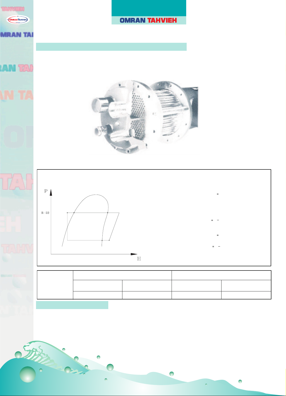
THERMOSTATIC EXPANSION VALVE: Thermostatic expansion valve is used to regulate the refrigerant flow to the
water cooler and maintain a constant superheat.
FILTER DRIER (REPLACEABLE CORE TYPE): Refrigerant circuits are kept free of harmful moisture, sludge, acids and
oil contaminating particles by the filter drier.
CONTROL CIRCUIT TRANSFORMER ( optional) : A factory mounted and wired control circuit transformer is furnished
eliminating the need for running a separate 115 volt power supply to the unit control circuit.
SIGHT GLASS: A moisture indicating sight glass installed in the liquid line. An easy-to-read color indicator shows mois-
ture contents and provides a mean for checking the system refrigerant charge.
LIQUID LINE SOLENOID VALVE: Closes when the compressor is off to prevent any liquid refrigerant from accumulating
in the water cooler during the off cycle.
DISCHARGE LINE MUFFLER ( optional ) : Discharge line mufflers are installed to eliminate noise due to refrigerant
pulsation.
VIBRATION ELIMINATOR: To eliminate the vibration transmitted from the compressor to the pipings and unit structure.
HOT GAS BYPASS SYSTEM (optional ) : Hot gas bypass is provided on the lead circuit to permit operation of the system
down to 50% of its unloaded capacity. Under low ambient condition, it controls temperature by eliminating the need to cycle
the compressoron and off, ensuring narrow temperature swing and lengthen the life span of the compressor .
WATER FLOW SWITCH (optional ): Paddle type field adjustable flow switch for water cooler circuits. Interlock into
unit safety circuits so that the unit will remain off until water flow is determine.
UNIT MOUNT SPRING ISOLATORS (optional): Designed for deflection. This housed spring assemblies have a
neoprene friction pad on the bottom to prevent vibration transmission.
CIRCUIT BREAKERS: Protects against compressor branch circuit fault. When tripped (manually or automatically), the
breaker opens the power supply to the compressor and control circuit through auxiliary contacts.
ACCESSORIES

AIR COOLED CHILLERS
PHYSICAL DATA
9
MODEL NUMBER OALC 010 OALC 015 OALC 025 OALC 030 OALC 035 OALC 040 OALC 050 OALC 060 OALC 070
COMPRESSOR
PART NUMBER 208/230V-3Ph-60Hz 800-677-44 800-677-50 800-677-62 800-677-68 800-677-71
380V-3Ph-60Hz 800-677-45 800-677-51 800-677-63 800-677-69 800-677-72
460V-3Ph-60Hz 800-677-46 800-677-52 800-677-64 800-677-70 800-677-73
380/415V-3Ph-50Hz 800-677-49 800-677-55 800-677-70 800-677-73 800-677-76
NUMBER OF COMPRESSORS 1 1 1 1 1 2222
TOTAL COMPRESSOR DISPLACEMENT, CFM 27.96 39.85 59.98 78.52 90.05 104.56 119.98 157.04 180.1
OIL CHARGE PER COMPRESSOR, Liters (Gallons) 3.2 (0.85) 3.2 (0.85) 4.7 (1.24) 5 (1.32) 5 (1.32) 4.7 (1.24) 4.7 (1.24) 5 (1.32) 5 (1.32)
% FULL LOAD CAPACITY CONTROL (optional) 100-50-0 100-66-0 100-75-50-25-0 100-83-50-33-0
MOTOR OVERLOAD PROTECTION (INTERNAL) ELECTRONIC
OIL LUBRICATION PUMP
TOTAL CRANKCASE HEATER WATTS 100 100 140 140 140 280 280 280 280
REFRIGERANT R-22
EXPANSION DEVICE EXPANSION VALVE
CONTROL VOLTAGE 220V-1Ph-50/60Hz
AIRCOOLED CONDENSER
CONDENSER COIL TubeDia.-Rows- Fins per inch 3/8- 3 3/8- 4 3/8- 4 3/8- 3 3/8- 3 3/8- 3 3/8- 4 3/8- 3 3/8- 4
Total face area, Sq. ft. 16.6 16.6 44.6 46.6 46.6 70 70 105 105
NUMBER OF FAN/FAN DIA.,Inches 2/30 2/30 3/30 4/30 4/30 6/30 6/30 6/30 6/30
FAN MOTOR HP/QUANTITY 1.5/2 1.5/2 1.5/3 1.5/4 1.5/4 1.5/6 1.5/6 1.5/6 1.5/6
FAN MOTOR RPM (60Hz/50Hz) 1140/950 1140/950 1140/950 1140/950 1140/950 1140/950 1140/950 1140/950 1140/950
COOLER
COOLER PART NUMBER 800-515-35 800-515-36 800-515-37 800-515-38 800-515-39 800-515-40 800-515-41 800-515-42 800-515-43
SHELL DIAMETER, mm 140 168 168 193 193 193 220 220 273
TOTAL LENGTH, mm 1500 1500 1500 2000 2000 2000 2000 3000 3000
WATER VOLUME, Liters (Gallons) 10.8 (2.85) 15.6 (4.12) 21.2 (5.6) 29.3 (7.74) 29.3 (7.74) 37.2 (9.83) 47.2(12.47) 55.8(14.74) 68.7(18.15)
THREADED/FLANGED WATER IN/OUT PIPE DIA. 2" MPT 2.5" MPT 2.5" MPT 3" MPT 3" MPT 3" MPT 100 mm 100 mm 125 mm
GENERAL
NUMBER OF REFRIGERANT CIRCUITS 1 1 1112222
REFRIGERANT CHARGE PER COMPRESSOR, kg 7.7 11.4 22.7 27.3 29.5 25 28 32 34
SHIPPING/OPERATING WEIGHTS, kg 627/645 713/733 895/921 1045/1075 1302/1330 1609/1652 1614/1657 2120/2208 2180/2262
800-677-62 (1)
800-677-22 (1)
800-677-68 (1)
800-677-28 (1)
800-677-71 (1)
800-677-31 (1)
800-677-63 (1)
800-677-23 (1)
800-677-69 (1)
800-677-29 (1)
800-677-72 (1)
800-677-32 (1)
800-677-64 (1)
800-677-24 (1)
800-677-70 (1)
800-677-30 (1)
800-677-73 (1)
800-677-33 (1)
800-677-70 (1)
800-677-30 (1)
800-677-73 (1)
800-677-33 (1)
800-677-76 (1)
800-677-36 (1)
800-677-59 (1)
800-677-19 (1)
800-677-60 (1)
800-677-20 (1)
800-677-61 (1)
800-677-21 (1)
800-677-64 (1)
800-677-24 (1)
NOTES:
Compressor with cylinder unloader.
1. All compressors operate at 1750 RPM @ 60Hz and 1450 RPM @ 50Hz.
2. Cooler vent and drain size are 1/2" MPT.
3. All barrels are single face refrigerant connection.

AIR COOLED CHILLERS
10
PHYSICAL DATA
MODEL NUMBER OALC 080 OALC 100 OALC 120 OALC 140 OALC 160 OALC 180 OALC 200 OALC 220 OALC 240
COMPRESSOR
NUMBER OF COMPRESSORS 2 2(4) 2(3) 4 4 4 4(5) 4(5) 4(6)
TOTAL COMPRESSOR DISPLACEMENT, CFM 215.4 255 296.5 360.2 430.4 468 511 552 593
OIL CHARGE PER COMPRESSOR, Liters (Gallons) 5 (1.32) 7.5 (1.98) 7.5 (1.98) 5 (1.32) 5 (1.32) 7.5 (1.98) 7.5 (1.98) 7.5 (1.98) 7.5 (1.98)
% FULL LOAD CAPACITY CONTROL (optional) 100-83-50-33-0 100-75-50-25-0 100-91-75-67-50-42-25-16-0 100-87-75-62-50-37-25-12-0
MOTOR OVERLOAD PROTECTION (INTERNAL) ELECTRONIC
OIL LUBRICATION PUMP
TOTAL CRANKCASE HEATER WATTS 280 400 400 560 560 800 800 800 800
REFRIGERANT R-22
EXPANSION DEVICE EXPANSION VALVE
CONTROL VOLTAGE 220V-1Ph-50/60Hz
AIRCOOLED CONDENSER
CONDENSER COIL TubeDia.-Rows- Finsperinch 3/8- 3 3/8- 3 3/8- 4 3/8- 3 3/8- 4 3/8- 4 3/8- 4 3/8- 4 3/8- 4
Total face area, Sq. ft. 201 201 201 232 232 280 322 322 360
NUMBER OF FAN/FAN DIA.,Inches 8/30 8/30 12/30 12/30 14/30 14/30 16/30 16/30 18/30
FAN MOTOR HP/QUANTITY 1.5/8 1.5/8 1.5/12 1.5/12 1.5/14 1.5/14 1.5/16 1.5/16 1.5/18
FAN MOTOR RPM (60Hz/50Hz) 1140/950 1140/950 1140/950 1140/950 1140/950 1140/950 1140/950 1140/950 1140/950
COOLER
COOLER PART NUMBER 800-515-44 800-515-45 800-515-46 800-515-47 800-515-48 800-515-48 800-515-49 800-515-50 800-515-51
SHELL DIAMETER, mm 273 323 323 323 406 406 406 406 406
TOTAL LENGTH, mm 3000 3000 3000 3000 3000 3000 3000 3000 3000
WATER VOLUME, Liters (Gallons) 77.9 (20.58) 79.8 (21.08) 79.8 (21.08) 110 (29.06) 153.4 (40.53) 153.4 (40.53) 169.4(44.76) 196.8 (52) 207.5 (54.82)
VICTAULIC WATER IN/OUT PIPE DIA. 125 mm 150 mm 150 mm 150 mm 200 mm 200 mm 200 mm 200 mm 200 mm
GENERAL
NUMBER OF REFRIGERANT CIRCUITS 2 2 2 444444
REFRIGERANT CHARGE PER COMPRESSOR, kg 42.5 45 50 42 42.5 45 45 50 50
SHIPPING/OPERATING WEIGHTS, kg 2522/2627 2522/2638 2522/2638 4120/4309 4409/4598 4943/5119 5232/5408 5354/5568 5477/5691
PART NUMBER 208/230V-3Ph-60Hz
380V-3Ph-60Hz
460V-3Ph-60Hz
380/415V-3Ph-50Hz
800-674-42*(1)
800-674-39 (1)
800-674-48*(1)
800-674-45 (1)
800-677-71*(1)
800-677-31 (3)
800-674-42*(1)
800-674-39 (1)
800-674-51 (2)
800-674-42*(1)
800-674-39 (3)
800-674-48*(1)
800-674-45 (1)
800-674-39 (2)
800-674-48*(1)
800-674-45 (3)
800-677-74*(1)
800-677-34 (1)
800-677-74*(1)
800-677-34 (3)
800-674-43*(1)
800-674-40 (1)
800-674-49*(1)
800-674-46 (1)
800-677-72*(1)
800-677-32 (3)
800-674-43*(1)
800-674-40 (1)
800-674-61 (2)
800-674-43*(1)
800-674-40 (3)
800-674-49*(1)
800-674-46 (1)
800-674-43 (2)
800-674-49*(1)
800-674-46 (3)
800-677-75*(1)
800-677-35 (1)
800-677-75*(1)
800-677-35 (3)
800-674-44*(1)
800-674-41 (1)
800-674-50*(1)
800-674-47 (1)
800-677-73*(1)
800-677-33 (3)
800-674-44*(1)
800-674-41 (1)
800-674-53 (2)
800-674-44*(1)
800-674-41 (3)
800-674-50*(1)
800-674-47 (1)
800-674-41 (2)
800-674-50*(1)
800-674-47 (3)
800-677-76*(1)
800-677-36 (1)
800-677-76*(1)
800-677-36 (3)
800-674-50*(1)
800-674-47 (1)
800-680-20*(1)
800-680-21 (1)
800-677-76*(1)
800-677-36 (3)
800-674-44*(1)
800-674-41 (3)
800-674-50*(1)
800-674-47 (3)
800-680-20*(1)
800-680-21 (1)
800-680-15 (2)
800-680-20*(1)
800-680-21 (3)
800-674-44*(1)
800-674-41 (1)
800-674-44*(1)
800-674-41 (1)
800-674-53 (2)
NOTES:
*Compressor with cylinder unloader.
1. All compressors operate at 1750 RPM @ 60Hz and 1450 RPM @ 50Hz.
2. Cooler vent and drain size are 1/2" MPT.
3. All barrels are single face refrigerant connection.

AIR COOLED CHILLERS
SELECTION PROCEDURE (English units)
11
DESIGN REQUIREMENTS
The followingdesign requirementsmust be known to select a package chiller.
1. Required cooling capacity in tons
2. Leaving chilled water temperature in 0F (LCWT)
3. Chilled water flow rate in PM
4. Chilled water cooling range in 0F (water in temp. _water out temp.)
5. Design ambient temperature
6. Minimum ambient temperature
7. Altitude
8. Electrical power supply
SAMPLE SELECTION
Select an Air Cooled Packaged chiller for the following conditions:
Required system capacity is 90 tons at 540F entering chilled water
and 440F leaving water. Design ambient temperature is 950F.
Altitude is 2000 feet above sea level.
Water cooler fouling factor is 0.00010. Power supply: 380V-3Ph-60Hz.
STEP-1: UNIT SELECTION
Entering the capacity performance data at given LCWT and ambient temperature.
OALC100 chiller unit at sea level will produce100.3 tons and 113.5kW compressor
power input at 440F leaving chilled water temperature with 100F water temperature
difference and 950F ambient temperature.
For the conditions required, the unit actual cooling capacity when corrected for
altitude (0.99) and fouling factor (1.0).
Capacity = 100.3x0.99x1.0 = 99.2 Tons, which then exceeds the requirements.
So the selection is correct.
STEP-2: CHILLED WATER FLOW ( PM):
Water PM = Required capacity (Tons) x 24 =90x24 = 216 PM
Cooling Range, DT 100F
ELEV ATION ABOVE
SEA LEVEL (FT .)
CAPACITY
CORRECTION
FACT OR
0
2000
4000
6000
1.00
0.99
0.98
0.97
TABLE- 1
TABLE - 3
TABLE - 2
EVAPORATOR FOULING
FACTOR (HR-FT2-0F/BTU)
0.00010
0.00025
0.00050
0.00075
0.00100
CAPACITY
CORRECTION
FACT OR
1.000
0.992
0.978
0.965
0.951
POWER
INPUT
FACT OR
1.000
0.997
0.990
0.984
0.978
ARI
STANDARDS
ARI-550/590-98
ARI-590-86
ARI-590-81
Referring to pressure drop chart, pressure drop at 216 PM = 11.5 ft. of water for selected model.
STEP-3: ELECTRICAL
Refer to electrical data at 380V-3Ph-60Hz, the main power wire size for OALC100 is to be sized for a minimum
circuit ampacity (MCA) of 325.4 Amps and maximum over current protection (MOCP) of 450 Amps.
STEP-4: CHILLED WATER PUMP SELECTION
For chilled water pump selection, add all pressure drop in the closed chilled water loop piping to the pressure drop
calculated in step 2.
STEP-5: LCWT CORRECTION
When a corrected LCWT is used, cooler pressure drop must also be corrected for new LCWT.
Refer to table-3. Add correction factor to design leaving chilled water temperature (LCWT) when chilled water tempera-
ture range is above 100F and subtract correction from design leaving chilled water temperature (LCWT) when water
temperature range is below 100F.
EXAMPLE:
If LCWT rise is 12.50F, enter correction curve at 12.50F and read the correction factor of 0.2. The corrected LCWT is
44+0.2 = 44.20F.
NOTE: 1. When the chilled water temperature rise is less than 50F, the high water flow rate will result to excessive
pressure drop. In such cases, contact factory for special selection of a cooler with wider baffle spacing.
2.Please refer to water pressure drop curves.
-0.4
-0.2
0
+0.2
+0.4
+0.6
5 101 52 0
COOLER WATER TEMPERATURE RISE ( F)
CORRECTION FACTOR ( F)

AIR COOLED CHILLERS
12
DESIGN REQUIREMENTS
The followingdesign requirementsmust be known to select a proper package chiller.
1. Required cooling capacity in kilowatt (kW)
2. Leaving chilled water temperature in 0C (LCWT)
3. Chilled water flow rate in LPS
4. Chilled water cooling range in 0C (water in temp. _water out temp.)
5. Design ambient temperature
6. Minimum ambient temperature
7. Altitude
8. Electrical power supply
SAMPLE SELECTION
Select an Air Cooled Packagedchiller for the following conditions:
Required system capacity is 300 kW at 12
0C entering chilled water
and 60C leaving water. Design ambient temperature is 350C.
Altitude is 600 meter above sea level.
Water cooler fouling factor is 0.000018. Power supply: 380V-3Ph-60Hz.
STEP-1: UNIT SELECTION
Entering the capacity performance data at given LCWT and ambient temperature.
OALC100 chiller unit at sea level will produce346.3 kW and 111.8 kW compressor
power input at 60C leaving chilled water temperature with 60C water temperature
difference and 350C ambient temperature.
For the conditions required, the unit actual cooling capacity when corrected for
altitude (0.99) and fouling factor (1.0).
Capacity = 346.3x0.99X1.0 = 342.84 kW, which then exceeds the requirements.
So the selection is correct.
STEP-2: CHILLED WATER FLOW (LPM):
Water LPS = Required capacity (kW) x 0.239 =300 x 0.239 =12LPS
Cooling Range, DT 60C
ELEVATION ABOVE
SEA LEVEL (Meter)
CAPACITY
CORRECTION
FACT OR
0
600
1200
1800
1.00
0.99
0.98
0.97
TABLE- 1
Referring to pressure drop chart, pressure drop at 12 LPS with pressure drop of 27.5 kPa of water for selected model.
STEP-3: ELECTRICAL
Refer to electrical data at 380V-3Ph-60Hz, the main power wire size for OALC100 is to be sized for a minimum
circuit ampacity (MCA) of 325.4 Amps and maximum over current protection (MOCP) of 450 Amps.
STEP-4: CHILLED WATER PUMP SELECTION
For chilled water pump selection, add all pressure drop in the closed chilled water loop piping to the pressure drop
calculated in step 2.
STEP-5: LCWT CORRECTION
When a corrected LCWT is used, cooler pressure drop must also be corrected for new LCWT.
Refer to table-3. Add correction factor to design leaving chilled water temperature (LCWT) when chilled water tempera-
ture range is above 60C and subtract correction from design leaving chilled water temperature (LCWT) when water
temperature range is below 60C.
EXAMPLE:
If LCWT rise is 7.40C, enter correction curve at 7.40C and read the correction factor of 0.11. The corrected LCWT is
60C+0.11 = 6.110C.
NOTE: 1. When the chilled water temperature rise is less than 30C, the high water flow rate will result to excessive
pressure drop. In such cases, contact factory for special selection of a cooler with wider baffle spacing.
2.Please refer to water pressure drop curves.
TABLE - 2
EVAPORA TOR FOULING
FACTOR (M2-0C/W)
0.000018
0.000044
0.000088
0.000132
0.000176
CAPACITY
CORRECTION
FACT OR
1.000
0.992
0.978
0.965
0.951
POWER
INPUT
FACT OR
1.000
0.997
0.990
0.984
0.978
ARI
STANDARDS
ARI-550/590-98
ARI-590-86
ARI-590-81
TABLE - 3
-0.22
-0.11
0
+0.11
+0.22
+0.33
4 567 89 10
COOLER WAT ER TEMPERATURE RISE ( C)
CORRECTION FACTOR (C)
SELECTION PROCEDURE (Metric units)

AIR COOLED CHILLERS
ETHYLENE GLYCOL SOLUTION CAPACITY CORRECTION (Antifreeze)
13
When operating in areas with temperatures below 320F(0
0C), cooler protection in the form of Ethylene glycol solution
(brine solution) is required to protect cooler from low ambient freeze-up. This brine solution must be added to water loop
to bring down the freezing point with a difference of 150F(8
0C) below minimum operating ambient temperature.
Ethylene glycol solution causes a variation in unit performance. To obtain the effective performance, it is necessary to
multiply the water performance data by correction factors corresponding to the ambient temperature or Ethylene glycol
percentage indicated in the following table.
EXAMPLE: English system- Determine Ethylene glycol percentage by weight and correction factors at 380F ambient
temperature.
From the above table, Ethylene glycol water solution concentration (percentage by weight) corresponding to 380F ambi-
ent temperature is 12% by weight.
Find the correction factors corresponding to 380F ambient temperature from the table.
Cooling capacity correction factor is 0.985, Flow correction factor is 1.02, Pressure drop correction factor is 1.07.
Apply these correction factors for corrected system performance values.
TONS (E.G. SOLUTION) = Tons (water) x Cooling capacity correction factor.
BRINE (E.G. SOLUTION) FLOW (GPM) = Flow (water) x Flow correction factor.
BRINE (E.G. SOLUTION) PRESSURE DROP = Water pressure drop (Ft.) x Pressure drop correction factor.
EXAMPLE: Metric system- Determine Ethylene glycol percentage by weight and correction factors where 3.30C ambi-
ent temperature.
From the above table, Ethylene glycol water solution concentration (percentage by weight) corresponding to 3.30C
ambient temperature is 12% by weight.
Find the correction factors corresponding to 3.30C ambient temperature from the table.
Cooling capacity correction factor is 0.985, Flow correction factor is 1.02, Pressure drop correction factor is 1.07.
Apply these correction factors for corrected system performance values.
KW (E.G. SOLUTION) = KW (water) x Cooling capacity correction factor.
BRINE (E.G. SOLUTION) FLOW (L/S) = KW (water) x Flow correction factor.
BRINE (E.G. SOLUTION) PRESSURE DROP = Water pressure drop (kPa) x Pressure drop correction factor.
Note: Correction factors apply to published chilled water performance rating from 400Fto50
0F (4.40Cto10
0C) LCWT.
ETHYLENE GLYCOL % BY WEIGHT 0% 12% 22% 30% 36% 41% 46% 50%
Freezing point of Ethylene glycol solution 00C (320F) -50C(23
0F) -100C (140F) -150C(5
0F) -200C (-40F) -250C (-130F) -300C (-220F) -350C (-310F)
Ambient temperature 8.30C (470F) 3.30C (380F) -1.70C (290F) -6.70C (200F) -11.70C(11
0F) -16.70C(2
0F) -21.70C (-70F) -26.70
C (-160
F)
Cooling capacity correction factor 1.0 0.985 0.980 0.974 0.970 0.965 0.964 0.960
Water flow correction factor 1.0 1.02 1.04 1.075 1.11 1.14 1.17 1.20
Pressure drop correction factor 1.0 1.07 1.11 1.18 1.22 1.24 1.27 1.30

AIR COOLED CHILLERS
PERFORMANCE DATA, 60Hz (English units)
14
40 0F
42 0F
44 0F
LEAVING
CHILLED
WATER TEMP.
(LCWT)
PERFORMANCE DATA, 60Hz
(English units)
WATER FLOW
(GPM)
EER
MODEL
No.
OALC 010
OALC 015
OALC 025
OALC 030
OALC 035
OALC 040
OALC 050
OALC 060
OALC 070
OALC 080
OALC 100
OALC 120
OALC 140
OALC 160
OALC 180
OALC 200
OALC 220
OALC 240
OALC 010
OALC 015
OALC025
OALC 030
OALC 035
OALC 040
OALC 050
OALC 060
OALC 070
OALC 080
OALC 100
OALC 120
OALC 140
OALC 160
OALC 180
OALC 200
OALC 220
OALC 240
OALC 010
OALC 015
OALC 025
OALC 030
OALC 035
OALC 040
OALC 050
OALC 060
OALC 070
OALC 080
OALC 100
OALC 120
OALC 140
OALC 160
OALC 180
OALC 200
OALC 220
OALC 240
11.6
17.2
25.1
31.8
37.6
42.3
50.2
63.6
75.3
93.1
110.2
130.0
150.6
186.2
201.6
220.5
240.5
260.1
11.8
17.6
25.5
32.3
38.3
42.9
51.0
64.6
76.5
94.5
112.0
132.5
153.0
189.0
204.4
224.0
244.3
264.9
12.0
17.8
25.9
32.7
38.9
43.5
51.8
65.4
77.7
95.7
113.5
134.6
155.4
191.5
207.2
227.2
247.9
269.2
8.6
8.7
8.9
9.2
8.6
9.1
8.9
9.4
9.3
8.9
9.4
9.0
9.3
9.0
9.5
9.4
9.3
9.2
8.8
9.0
9.2
9.5
8.9
9.3
9.3
9.8
9.6
9.1
9.6
9.3
9.6
9.2
9.7
9.6
9.6
9.5
9.1
9.3
9.5
9.8
9.2
9.7
9.5
10.1
9.9
9.5
9.9
9.5
9.9
9.5
10.0
9.9
9.8
9.7
23.6
33.8
50.5
66.2
76.1
88.3
101.0
132.3
152.2
180.6
223.9
257.7
304.5
361.2
410.4
447.2
480.1
515.4
24.6
35.4
53.1
69.4
79.6
92.3
106.5
138.8
159.2
188.3
232.1
269.1
318.6
377.1
425.4
464.2
501.7
538.3
25.9
37.0
55.5
72.7
83.3
96.5
110.9
145.3
166.7
197.3
242.3
280.6
333.6
394.5
444.3
484.6
522.2
562.2
8.9
13.0
19.6
25.6
29.6
34.2
39.1
51.3
59.1
70.0
86.0
98.9
118.2
140.2
158.1
172.4
185.1
198.0
9.5
13.7
20.6
26.9
30.9
35.8
41.2
54.0
61.8
73.1
89.3
103.5
123.6
146.3
163.8
178.6
193.2
207.1
9.8
14.3
21.5
28.2
32.3
37.5
43.1
56.4
64.7
76.6
93.3
108.3
129.4
153.3
171.1
186.6
202.3
216.6
12.4
18.5
27.1
34.2
40.7
45.5
54.2
68.4
81.4
99.8
117.5
137.4
162.7
199.6
214.9
235.1
255.0
274.9
12.8
18.8
27.5
34.8
41.4
46.3
55.1
69.6
82.8
101.2
119.6
140.2
165.6
202.4
218.6
239.0
259.6
280.2
13.0
19.1
28.0
35.3
42.0
47.2
56.1
70.6
84.0
102.8
121.4
142.5
168.0
205.6
221.8
242.9
263.7
284.4
7.4
7.6
7.8
8.0
7.6
7.9
7.8
8.3
8.1
7.8
8.2
7.9
8.1
7.9
8.3
8.3
8.2
8.1
7.7
7.9
8.1
8.3
7.8
8.2
8.1
8.6
8.4
8.0
8.4
8.2
8.4
8.1
8.5
8.4
8.4
8.3
7.9
8.1
8.3
8.6
8.1
8.4
8.3
8.8
8.6
8.3
8.7
8.4
8.6
8.4
8.7
8.7
8.7
8.6
21.6
31.3
47.3
61.9
71.4
82.6
94.5
123.9
142.8
169.1
207.7
238.8
285.6
338.5
381.8
416.4
447.0
478.1
22.9
33.1
49.8
65.1
74.6
86.6
99.5
130.3
149.2
176.6
215.7
250.0
298.5
353.2
395.5
431.3
466.6
500.2
23.9
34.6
52.0
68.1
78.1
90.5
104.0
136.3
156.2
185.1
225.4
261.4
312.4
370.1
413.2
450.7
488.5
523.1
8.3
12.3
18.4
24.0
27.6
31.9
36.9
48.0
55.2
65.6
80.6
92.6
110.4
131.2
147.9
161.3
172.9
185.2
8.8
12.9
19.2
25.1
28.8
33.5
38.3
50.3
57.7
68.5
82.9
97.2
115.4
137.0
152.4
165.9
181.6
194.6
9.2
13.5
20.1
26.4
30.2
35.0
40.2
52.7
60.4
71.8
86.7
101.8
120.8
143.6
159.7
173.5
189.7
200.5
13.2
19.7
29.4
37.1
44.1
49.6
58.9
74.3
88.2
107.1
123.9
143.3
176.5
214.1
226.6
247.7
267.2
286.6
13.5
20.0
30.0
37.8
45.0
50.4
59.9
75.7
90.1
108.9
126.9
146.1
180.1
217.8
230.7
253.7
272.0
292.4
13.8
20.4
30.6
38.5
45.8
51.4
61.1
76.9
91.7
110.7
128.9
148.9
183.4
221.4
234.2
257.9
276.9
299.1
6.6
6.8
6.8
7.0
6.6
6.9
6.8
7.2
7.0
6.8
7.4
7.2
7.0
6.9
7.4
7.4
7.3
7.3
6.8
7.0
7.0
7.2
6.8
7.1
7.0
7.4
7.2
7.0
7.4
7.4
7.2
7.1
7.5
7.4
7.6
7.5
7.0
7.2
7.2
7.4
7.0
7.3
7.2
7.6
7.4
7.3
7.6
7.6
7.4
7.3
7.7
7.6
7.8
7.6
20.1
29.6
44.5
58.0
66.7
77.1
89.1
115.9
133.3
158.5
194.8
223.6
266.7
316.9
357.2
389.5
417.6
447.2
21.4
31.1
46.3
60.7
69.6
80.8
92.5
121.4
139.3
165.4
200.2
234.8
278.6
330.8
368.1
400.7
438.5
469.9
22.4
32.6
48.5
63.7
72.9
84.6
97.0
127.4
145.8
173.4
209.4
245.8
291.8
346.8
385.6
418.9
458.2
484.3
7.7
11.5
17.3
22.4
25.6
29.7
34.6
44.7
51.3
61.2
75.3
86.3
102.6
122.4
137.7
150.2
160.8
172.4
8.2
11.8
17.5
23.4
26.8
31.0
35.4
46.6
53.6
63.9
76.5
91.4
107.1
127.7
141.1
153.3
170
182
8.6
12.6
18.6
24.5
28.0
32.5
37.3
49.0
56.0
67.0
80.1
95.6
112.3
133.9
148.2
160.3
177.2
190.4
5.8
6.0
6.0
6.1
5.7
6.0
6.0
6.2
6.1
6.0
6.5
6.4
6.1
6.1
6.6
6.5
6.5
6.6
6.1
6.1
5.9
6.2
5.9
6.1
6.0
6.4
6.2
6.2
6.5
6.6
6.2
6.2
6.6
6.5
6.7
6.7
6.2
6.3
6.2
6.4
6.0
6.3
6.2
6.6
6.4
6.4
6.7
6.8
6.4
6.4
6.8
6.7
7.0
6.7
18.7
27.9
41.8
54.0
61.9
71.6
83.6
108.0
123.9
147.8
181.8
208.4
247.8
295.5
332.6
362.7
388.3
416.4
19.9
28.6
42.3
56.5
64.7
74.9
85.6
112.4
129.3
154.2
184.8
220.6
258.7
308.4
340.8
370.1
412.2
441.5
20.9
30.3
45.0
59.2
67.7
78.6
90.0
118.4
135.3
161.7
193.5
230.8
271.1
323.4
357.9
387.0
427.8
459.7
950F AMBIENTTEMPERATURE 1050F AMBIENT TEMPERATURE 1150F AMBIENT TEMPERATURE 1250F AMBIENT TEMPERATURE
CAP.
(Tons)
9.7
14.0
20.9
27.4
31.5
36.6
41.8
54.8
63.0
74.8
92.7
106.7
126.1
149.6
170.0
185.2
198.8
213.4
10.2
14.7
22.0
28.7
33.0
38.2
44.1
57.5
65.9
78.0
96.1
111.4
131.9
156.1
176.1
192.2
207.8
222.9
10.7
15.3
23.0
30.1
34.5
40.0
45.9
60.2
69.0
81.7
100.3
116.2
138.1
163.4
184.0
200.6
216.3
232.8
COMP.
kW
COOLER
WATER FLOW
(GPM)
EER
CAP.
(Tons)
COMP.
kW
COOLER
WATER FLOW
(GPM)
EER
CAP.
(Tons)
COMP.
kW
COOLER
WATER FLOW
(GPM)
EER
CAP.
(Tons)
COMP.
kW
COOLER
14.0
20.9
31.8
40.1
47.6
53.6
63.6
80.2
95.1
114.4
130.2
149.2
190.3
228.7
238.2
260.4
279.3
298.3
14.2
21.3
32.4
40.9
48.7
54.7
64.8
81.8
97.4
116.6
134.2
154.0
194.7
233.2
242.9
268.4
284.5
304.5
14.6
21.8
33.1
41.6
49.7
56.0
66.2
83.2
99.4
118.6
136.4
157.5
198.8
237.2
246.5
272.6
290.4
311.1
LEGEND:
kW - Compressor power input
PD - Pressure Drop
EER - Energy Efficiency Ratio
NOTES
1. For 50Hz units, multiply capacity by 0.85 & power input by 0.83.
2. Performance data are based on 10°F water range in evaporator.
3. Ratings are based on 0.00010 (hr-ft
2
-0F/Btu) fouling factor for evaporator.
4. Direct interpolation is permissible. Do not extrapolate.
5. kW power input is for compressor only.
6. EER for entire unit. Refer to physical data for fan kW.

AIR COOLED CHILLERS
PERFORMANCE DATA, 60Hz (English units)
15
46
0
F
48
0
F
50
0
F
LEAVING
CHILLED
WATER TEMP.
(LCWT)
PERFORMANCE DATA, 60Hz
(English units)
WATER FLOW
( PM)
EER
MODEL
No.
OALC 010
OALC 015
OALC 025
OALC 030
OALC 035
OALC 040
OALC 050
OALC 060
OALC 070
OALC 080
OALC 100
OALC 120
OALC 140
OALC 160
OALC 180
OALC 200
OALC 220
OALC 240
OALC 010
OALC 015
OALC 025
OALC 030
OALC 035
OALC 040
OALC 050
OALC 060
OALC 070
OALC 080
OALC 100
OALC 120
OALC 140
OALC 160
OALC 180
OALC 200
OALC 220
OALC 240
OALC 010
OALC 015
OALC 025
OALC 030
OALC 035
OALC 040
OALC 050
OALC 060
OALC 070
OALC 080
OALC 100
OALC 120
OALC 140
OALC 160
OALC 180
OALC 200
OALC 220
OALC 240
12.2
18.0
26.2
33.0
39.3
44.1
52.4
66.1
78.7
97.1
115.2
136.6
157.5
194.3
209.9
230.3
251.6
273.2
12.4
18.3
26.6
33.6
40.0
44.7
53.2
67.2
79.9
98.4
116.7
138.6
159.9
196.7
212.5
233.4
252.0
277.3
12.7
18.5
26.9
34.0
40.5
47.0
53.8
68.0
81.0
99.6
118.2
140.6
161.9
199.2
215.1
236.4
253.8
281.1
9.4
9.6
9.9
10.2
9.5
10.0
9.9
10.4
10.2
9.7
10.2
9.8
10.2
9.8
10.3
10.2
10.2
10.1
9.7
9.9
10.2
10.5
9.8
10.5
10.2
10.8
10.5
10.1
10.5
10.1
10.5
10.2
10.6
10.5
10.6
10.4
10.0
10.2
10.5
10.8
10.1
10.1
10.5
11.1
10.9
10.4
10.8
10.4
10.9
10.5
11.0
10.8
11.2
10.6
27.1
38.7
58.1
76.0
87.1
101.2
116.4
151.7
174.1
206.0
253.0
294.0
348.2
411.9
463.9
505.9
548.2
588.3
28.4
40.5
60.7
79.4
91.0
107.7
121.4
158.7
182.0
215.2
263.9
307.7
363.9
430.3
484.1
527.8
572.4
615.4
29.6
42.3
63.3
82.9
94.9
104.7
126.9
165.7
189.8
224.1
275.1
319.6
379.6
448.2
504.7
550.2
608.7
637.8
10.4
15.0
22.5
29.5
33.8
39.2
45.1
58.9
67.6
80.0
97.4
113.4
135.1
160.1
178.7
194.9
211.4
226.9
10.9
15.7
23.5
30.8
35.3
41.1
47.0
61.6
70.7
83.6
101.7
118.7
141.3
167.3
186.5
203.3
220.6
237.3
11.4
16.4
24.6
32.2
36.9
42.8
49.2
64.4
73.7
87.2
106.0
124.0
147.5
174.5
194.6
212.0
230.5
248.0
13.3
19.5
28.4
35.9
42.7
47.8
56.9
71.9
85.4
104.2
123.3
144.9
170.8
208.5
225.1
246.5
268.1
289.9
13.5
19.7
28.9
36.4
43.4
48.6
57.9
72.9
86.8
105.9
125.1
147.3
173.7
211.7
228.7
250.2
272.4
294.8
13.8
20.0
29.4
36.9
44.1
49.2
58.9
73.9
88.2
107.3
126.9
149.6
176.5
214.5
231.2
253.8
276.4
299.1
8.1
8.4
8.6
8.8
8.3
8.7
8.6
9.1
8.9
8.6
8.9
8.7
8.9
8.6
9.0
8.9
8.9
8.9
8.4
8.6
8.8
9.1
8.6
9.0
8.8
9.4
9.1
8.8
9.2
8.9
9.1
8.9
9.2
9.2
9.2
9.1
8.7
8.9
9.1
9.4
8.8
9.3
9.1
9.7
9.4
9.1
9.4
9.2
9.4
9.2
9.5
9.4
9.5
9.4
25.1
36.2
54.4
71.2
81.6
94.8
108.9
142.3
163.2
193.3
235.3
273.9
326.4
386.5
431.6
470.6
510.4
548.0
26.4
37.8
56.8
74.4
85.3
99.2
113.4
148.7
170.6
202.0
245.5
286.6
341.3
404.0
450.5
491.0
532.8
573.1
27.6
39.5
59.4
77.7
89.0
103.5
118.9
155.4
178.1
210.7
256.0
299.5
356.2
421.4
469.9
511.9
556.7
599.0
9.6
14.1
21.1
27.4
31.5
36.6
42.2
54.8
63.0
75.0
90.5
106.5
126.2
150.0
166.9
181.1
198.3
213.0
10.2
14.7
22.0
28.7
33.0
38.3
44.1
57.5
65.9
78.3
94.5
111.4
131.9
156.6
174.1
188.9
207.3
222.9
10.6
15.3
23.0
30.1
34.5
40.0
45.9
60.2
69.0
81.9
98.5
116.4
138.1
163.8
181.8
196.9
216.4
232.8
14.0
20.8
31.2
39.3
46.8
52.4
62.3
77.5
93.5
112.5
131.1
151.8
187.0
225.1
238.3
262.1
281.9
303.6
14.3
21.2
31.8
40.0
47.7
53.2
63.6
79.9
95.3
114.4
133.2
154.4
190.7
228.7
241.9
266.4
286.6
308.9
14.6
21.6
32.3
40.7
48.5
54.2
64.6
81.4
96.9
116.2
134.6
157.1
193.9
232.4
244.9
270.4
291.2
314.2
7.3
7.4
7.4
7.6
7.2
7.5
7.4
7.9
7.6
7.5
7.8
7.8
7.6
7.5
8.0
7.8
8.0
8.0
7.5
7.6
7.6
7.8
7.4
7.7
7.6
8.0
7.8
7.7
8.0
8.0
7.8
7.8
8.2
8.0
8.2
8.2
7.7
7.8
7.8
8.1
7.6
7.9
7.8
8.3
8.1
7.9
8.3
8.3
8.1
8.0
8.4
8.3
8.5
8.4
23.4
34.1
51.0
66.2
76.1
88.3
102.0
132.3
152.2
181.1
218.6
257.2
304.7
362.2
403.0
437.3
478.8
514.4
24.6
35.6
53.2
69.4
79.6
92.5
106.5
138.8
159.2
189.0
228.1
269.1
318.6
378.1
420.4
456.2
500.7
538.3
25.6
37.1
55.5
72.6
83.3
96.5
110.9
145.3
166.7
197.8
237.8
281.1
333.6
395.5
439.0
475.6
522.6
562.2
95
0
F AMBIENTTEMPERATURE 105
0
F AMBIENT TEMPERATURE 115
0
F AMBIENT TEMPERATURE 125
0
F AMBIENT TEMPERATURE
CAP.
(Tons)
11.2
16.0
24.1
31.5
36.1
41.9
48.2
62.8
72.1
85.3
104.8
121.7
144.2
170.6
192.1
209.5
227.0
243.6
11.7
16.8
25.1
32.9
37.7
43.8
50.3
65.7
75.4
89.1
109.3
127.4
150.7
178.2
200.4
218.6
237.0
254.8
12.3
17.5
26.2
34.3
39.3
45.6
52.5
68.6
78.6
92.8
113.9
132.4
157.2
185.6
209.0
227.8
252.0
264.1
COMP.
kW
COOLER
WATER FLOW
( PM)
EER
CAP.
(Tons)
COMP.
kW
COOLER
WATER FLOW
(GPM)
EER
CAP.
(Tons)
COMP.
kW
COOLER
WATER FLOW
(GPM)
EER
CAP.
(Tons)
COMP.
kW
COOLER
LEGEND:
kW - Compressor power input
PD - Pressure Drop
EER - Energy Efficiency Ratio
NOTES
1. For 50Hz units, multiply capacity by 0.85 & power input by 0.83.
2. Performance data are based on 100F water range in evaporator.
3. Ratings are based on 0.00010 (hr-ft
2
-0F/Btu) fouling factor for evaporator.
4. Direct interpolation is permissible. Do not extrapolate.
5. kW power input is for compressor only.
6. EER for entire unit. Refer to physical data for fan kW.
21.6
32.1
47.5
61.2
70.6
81.6
95.0
122.4
141.3
168.9
202.0
241.5
283.1
337.8
374.4
404.0
450.0
483.3
22.9
32.8
49.3
64.4
73.9
85.8
99.5
128.8
147.8
176.1
210.7
253.0
296.0
352.2
390.3
421.4
470.6
505.9
23.6
34.6
51.5
67.4
77.6
89.5
103.0
135.1
155.2
184.8
219.6
264.2
310.9
369.6
408.2
439.3
491.0
528.3
6.4
6.6
6.4
6.5
6.2
6.4
6.4
6.8
6.5
6.5
6.8
6.9
6.5
6.6
7.0
6.8
7.1
7.1
6.6
6.6
6.5
6.7
6.3
6.6
6.6
6.9
6.7
6.7
7.0
7.2
6.7
6.8
7.2
7.0
7.3
7.3
6.7
6.9
6.7
6.9
6.5
6.8
6.7
7.1
6.9
6.9
7.3
7.3
6.9
7.0
7.5
7.1
7.5
7.5
14.7
22.3
33.9
42.6
50.8
57.6
67.8
83.2
101.6
120.8
138.8
160.9
203.2
241.7
251.6
277.7
298.8
321.2
15.1
22.6
34.6
43.5
51.9
58.3
69.2
87.0
103.8
122.9
141.3
163.6
207.7
245.7
255.9
282.6
303.7
327.4
15.4
23.1
35.1
44.4
52.8
59.8
70.2
88.9
105.3
125.1
142.3
166.8
211.3
250.2
258.6
291.1
308.6
333.0
9.0
13.3
19.7
25.3
29.3
33.8
39.3
50.7
58.5
69.9
83.6
100.0
117.2
139.9
155.0
167.3
186.3
200.1
9.5
13.6
20.4
26.7
30.6
35.5
41.2
53.4
61.2
72.9
87.2
104.8
122.6
145.8
161.6
174.5
194.9
209.5
9.8
14.3
21.3
27.9
32.1
37.1
42.6
55.9
64.3
76.5
90.9
109.4
128.8
153.1
169.0
181.9
203.3
218.8

AIR COOLED CHILLERS
PERFORMANCE DATA, 60Hz (Metric units)
16
40C
50C
60C
LEAVING
CHILLED
WATER TEMP.
(LCWT)
PERFORMANCE DATA, 60Hz
(Metric units)
WATER FLOW
(LPS)
COP
MODEL
No.
OALC 010
OALC 015
OALC 025
OALC 030
OALC 035
OALC 040
OALC 050
OALC 060
OALC 070
OALC 080
OALC 100
OALC 120
OALC 140
OALC 160
OALC 180
OALC 200
OALC 220
OALC 240
OALC 010
OALC 015
OALC 025
OALC 030
OALC 035
OALC 040
OALC 050
OALC 060
OALC 070
OALC 080
OALC 100
OALC 120
OALC 140
OALC 160
OALC 180
OALC 200
OALC 220
OALC 240
OALC 010
OALC 015
OALC 025
OALC 030
OALC 035
OALC 040
OALC 050
OALC 060
OALC 070
OALC 080
OALC 100
OALC 120
OALC 140
OALC 160
OALC 180
OALC 200
OALC 220
OALC 240
11.5
17.0
24.8
31.5
37.3
41.9
49.7
62.9
74.5
92.2
109.1
128.7
149.1
184.3
199.6
218.3
238.0
257.5
11.7
17.4
25.2
32.0
37.9
42.5
50.5
63.9
75.7
93.6
110.9
131.1
151.5
187.2
202.4
221.7
241.9
262.3
11.9
17.5
25.5
32.2
38.3
42.9
51.0
64.4
76.6
94.3
111.8
132.6
153.1
188.6
204.0
223.8
244.2
265.2
2.5
2.4
2.6
2.6
2.5
2.6
2.6
2.7
2.7
2.6
2.7
2.6
2.7
2.6
2.7
2.7
2.7
2.7
2.5
2.6
2.7
2.7
2.6
2.7
2.7
2.8
2.8
2.6
2.8
2.7
2.8
2.7
2.8
2.8
2.8
2.7
2.6
2.7
2.8
2.8
2.7
2.8
2.8
2.9
2.9
2.7
2.9
2.8
2.9
2.8
2.9
2.9
2.9
2.8
1.35
1.82
2.88
3.77
4.34
5.03
5.76
7.54
8.68
10.29
12.76
14.69
17.35
20.58
23.39
25.49
27.36
29.37
1.40
2.02
3.03
3.96
4.54
5.26
6.07
7.91
9.07
10.7
13.2
15.3
18.2
21.5
24.2
26.5
28.6
30.7
1.47
2.11
3.16
4.14
4.74
5.49
6.32
8.27
9.49
11.2
13.8
16.0
19.0
22.5
25.3
27.6
29.7
32.0
31.0
44.8
67.6
88.6
102.2
118.2
135.3
177.3
204.3
242.0
297.2
341.7
408.6
484.4
546.4
595.8
639.6
684.1
32.7
47.3
71.3
93.1
106.8
123.9
142.4
186.5
213.6
252.7
308.6
357.7
427.1
505.4
565.9
617.2
667.7
715.8
34.1
49.4
74.3
97.4
111.6
129.4
148.7
194.8
223.3
264.5
322.1
373.7
446.6
529.1
590.6
644.3
698.3
747.8
12.3
18.3
26.9
33.9
40.3
45.1
53.7
67.7
80.6
98.8
116.3
136.1
161.1
197.6
212.8
232.7
252.5
272.1
12.6
18.6
27.3
34.5
41.0
45.9
54.5
68.9
82.0
100.2
118.4
138.8
163.9
200.4
216.4
236.6
257.0
277.4
12.8
18.9
27.6
34.8
41.4
46.5
55.2
69.6
82.7
101.3
119.6
140.4
165.5
202.6
218.5
239.2
259.8
280.1
2.1
2.2
2.2
2.3
2.2
2.3
2.2
2.4
2.3
2.3
2.4
2.3
2.3
2.3
2.4
2.4
2.4
2.3
2.2
2.3
2.3
2.4
2.3
2.4
2.3
2.5
2.4
2.3
2.4
2.4
2.4
2.3
2.4
2.4
2.4
2.4
2.3
2.4
2.4
2.5
2.3
2.4
2.4
2.6
2.5
2.4
2.5
2.4
2.5
2.4
2.5
2.5
2.5
2.5
1.23
1.79
2.69
3.53
4.07
4.71
5.39
7.06
8.14
9.64
11.84
13.61
16.27
19.29
21.76
23.73
25.48
27.25
1.30
1.88
2.84
3.71
4.25
4.93
5.67
7.43
8.51
10.07
12.29
14.25
17.01
20.13
22.54
24.58
26.60
28.51
1.36
1.97
2.96
3.88
4.45
5.16
5.92
7.76
8.89
10.54
12.83
14.88
17.79
21.07
23.52
25.66
27.81
29.78
28.8
42.4
63.7
82.9
95.4
110.3
127.4
165.9
190.8
226.7
278.7
320.0
381.6
453.5
511.1
557.4
597.6
640.0
30.6
44.5
66.2
86.8
99.7
115.7
132.4
173.7
199.3
236.7
286.5
336.0
398.6
473.4
526.8
573.4
627.5
672.4
32.0
46.6
69.3
91.0
104.2
120.9
138.7
182.1
208.4
247.8
299.4
351.3
417.1
495.7
551.1
598.8
655.0
692.3
13.0
19.2
29.2
36.8
43.7
49.1
58.3
73.5
87.4
106.0
122.6
141.9
174.7
212.0
224.3
245.3
264.5
283.7
13.3
19.8
29.7
37.5
44.6
49.9
59.3
74.9
89.2
107.8
125.6
144.7
178.3
215.6
228.4
251.2
269.3
289.4
13.6
20.1
30.1
37.9
45.2
50.6
60.2
75.8
90.3
109.1
127.0
146.6
180.6
218.1
230.7
254.0
272.7
294.6
1.9
2.2
2.0
2.0
1.9
2.0
2.0
2.1
2.0
2.0
2.1
2.1
2.0
2.0
2.1
2.1
2.1
2.1
2.0
2.0
2.0
2.1
2.0
2.1
2.0
2.1
2.1
2.0
2.1
2.1
2.1
2.1
2.2
2.1
2.2
2.2
2.0
2.1
2.1
2.2
2.0
2.1
2.1
2.2
2.2
2.1
2.2
2.2
2.2
2.1
2.2
2.2
2.3
2.2
1.15
1.69
2.54
3.30
3.80
4.39
5.08
6.61
7.60
9.03
11.10
12.74
15.20
18.06
20.36
22.20
23.80
25.49
1.22
1.77
2.64
3.46
3.97
4.61
5.27
6.92
7.94
9.43
11.41
13.38
15.88
18.86
20.98
22.84
24.99
26.78
1.27
1.86
2.76
3.63
4.15
4.82
5.52
7.25
8.30
9.87
11.9
14.0
16.6
19.7
22.0
23.8
26.1
27.6
350C AMBIENTTEMPERATURE 400C AMBIENT TEMPERATURE 460C AMBIENT TEMPERATURE 520C AMBIENT TEMPERATURE
CAP.
(kW)
33.8
45.7
72.3
94.7
108.9
126.4
144.5
189.4
217.8
258.4
320.3
368.7
435.7
516.8
587.3
640.0
686.9
737.5
35.2
50.7
76.0
99.3
113.9
132.1
152.3
198.7
227.8
269.4
332.1
385.1
455.9
539.6
608.6
664.2
717.9
770.2
37.0
52.9
79.3
103.9
119.1
138.0
158.6
207.7
238.2
282.0
346.3
401.1
476.8
563.9
635.0
692.6
746.7
803.6
COMP.
kW
COOLER
WATER FLOW
(LPS)
COP
CAP.
(kW)
COMP.
kW
COOLER
WATER FLOW
(LPS)
COP
CAP.
(kW)
COMP.
kW
COOLER
WATER FLOW
(LPS)
COP
CAP.
(kW)
COMP.
kW
COOLER
LEGEND:
kW - Compressor power input
PD - Pressure Drop
COP - Coefficient of Performance
NOTES
1. For 50Hz units, multiply capacity by 0.85 & power input by 0.83.
2. Performance data are based on 60C water range in evaporator.
3. Ratings are based on 0.000018 (m
2
-0C/W) fouling factor for evaporator.
4. Direct interpolation is permissible. Do not extrapolate.
5. kW power input is for compressor only.
6. COP for entire unit. Refer to physical data for fan kW.
1.06
1.59
2.38
3.08
3.53
4.08
4.76
6.15
7.06
8.42
10.36
11.88
14.12
16.84
18.95
20.67
22.13
23.73
1.13
1.63
2.41
3.22
3.69
4.27
4.88
6.41
7.37
8.79
10.53
12.57
14.74
17.58
19.42
21.10
23.49
25.16
1.19
1.73
2.56
3.37
3.85
4.48
5.13
6.74
7.70
9.21
11.02
13.14
15.44
18.41
20.38
22.04
24.36
26.1
1.7
1.7
1.7
1.8
1.7
1.7
1.7
1.8
1.8
1.7
1.9
1.9
1.8
1.8
1.9
1.9
1.9
1.9
1.8
1.8
1.7
1.8
1.7
1.8
1.7
1.8
1.8
1.8
1.9
1.9
1.8
1.8
1.9
1.9
1.9
1.9
1.8
1.8
1.8
1.9
1.7
1.8
1.8
1.9
1.9
1.8
1.9
2.0
1.9
1.9
2.0
1.9
2.0
1.9
13.8
20.7
31.5
39.7
47.1
53.1
62.9
79.3
94.2
113.2
128.9
147.7
188.4
226.4
235.8
257.8
276.5
295.4
14.0
21.0
32.1
40.5
48.2
54.2
64.1
81.0
96.4
115.4
132.8
152.5
192.8
230.8
240.5
265.7
281.6
301.4
14.4
21.4
32.6
41.0
48.9
55.1
65.2
81.9
97.9
116.8
134.4
155.1
195.8
233.7
242.8
268.5
286.1
306.4
26.7
39.9
59.8
77.2
88.6
102.5
119.6
154.5
177.3
211.4
260.2
298.3
354.5
422.8
475.9
518.9
555.6
595.8
28.5
40.9
60.5
80.8
92.5
107.1
122.4
160.9
185.1
220.7
264.5
315.7
370.2
441.4
487.6
529.6
587.3
628.9
29.9
43.4
64.4
84.6
96.7
112.4
128.7
169.3
193.4
231.1
276.6
329.0
387.6
462.2
511.7
553.3
611.6
657.1

AIR COOLED CHILLERS
PERFORMANCE DATA, 60Hz (Metric units)
17
70C
80C
100C
LEAVING
CHILLED
WATER TEMP.
(LCWT)
PERFORMANCE DATA, 60Hz
(Metric units)
COP
MODEL
No.
OALC 010
OALC 015
OALC 025
OALC 030
OALC 035
OALC 040
OALC 050
OALC 060
OALC 070
OALC 080
OALC 100
OALC 120
OALC 140
OALC 160
OALC 180
OALC 200
OALC 220
OALC 240
OALC 010
OALC 015
OALC 025
OALC 030
OALC 035
OALC 040
OALC 050
OALC 060
OALC 070
OALC 080
OALC 100
OALC 120
OALC 140
OALC 160
OALC 180
OALC 200
OALC 220
OALC 240
OALC 010
OALC 015
OALC 025
OALC 030
OALC 035
OALC 040
OALC 050
OALC 060
OALC 070
OALC 080
OALC 100
OALC 120
OALC 140
OALC 160
OALC 180
OALC 200
OALC 220
OALC 240
12.1
17.8
25.8
32.6
38.8
43.5
51.6
65.2
77.6
95.7
113.4
134.6
155.1
191.4
206.7
226.9
247.8
269.1
12.3
18.0
26.2
33.1
39.4
44.1
52.4
66.2
78.7
96.9
114.9
136.6
157.5
193.8
209.3
229.9
248.2
273.1
12.7
18.5
26.9
34.0
40.5
45.3
53.8
68.0
81.0
99.6
118.2
140.6
161.9
199.2
215.1
236.4
253.8
281.1
2.7
2.8
2.8
2.9
2.7
2.9
2.8
3.0
2.9
2.8
2.9
2.8
2.9
2.8
3.0
2.9
2.9
2.9
2.77
2.82
2.90
2.99
2.79
3.00
2.90
3.07
3.00
2.87
3.00
2.89
3.00
2.90
3.03
3.00
3.03
2.96
2.9
3.0
3.1
3.2
3.0
3.0
3.1
3.3
3.2
3.0
3.2
3.0
3.2
3.1
3.2
3.2
3.3
3.1
1.53
2.19
3.29
4.30
4.93
5.73
6.59
8.59
9.85
11.7
14.3
16.6
19.7
23.3
26.3
28.6
31.0
33.3
1.59
2.27
3.40
4.45
5.10
5.91
6.80
8.89
10.19
12.05
14.78
17.23
20.38
24.10
27.11
29.56
32.05
34.46
1.73
2.47
3.69
4.84
5.54
6.41
7.40
9.66
11.07
13.07
16.05
18.65
22.14
26.15
29.44
32.10
35.51
37.20
37.5
51.4
77.3
101.1
115.9
134.6
154.6
202.2
231.9
274.6
334.3
389.1
463.6
549.2
613.1
668.6
725.1
778.5
34.6
53.2
79.9
104.7
120.0
139.5
159.5
209.1
239.9
284.0
345.2
402.9
479.8
568.0
633.4
690.4
749.1
805.8
37.5
57.9
87.0
113.8
130.4
151.6
174.1
227.6
260.8
308.6
374.9
438.6
521.7
617.1
688.2
749.8
815.3
877.3
13.3
19.2
28.0
35.4
42.1
47.0
56.0
70.8
84.1
102.7
121.4
142.7
168.3
205.3
221.7
242.8
264.1
285.6
14.1
19.4
28.5
35.9
42.8
47.8
57.0
71.8
85.5
104.3
123.2
145.1
171.1
208.5
225.3
246.4
268.3
290.4
14.6
20.0
29.4
36.9
44.1
49.2
58.9
73.9
88.2
107.3
126.9
149.6
176.5
214.5
231.2
253.8
276.4
299.1
2.4
2.4
2.5
2.5
2.4
2.5
2.5
2.6
2.6
2.5
2.6
2.5
2.6
2.5
2.6
2.6
2.6
2.6
2.1
2.5
2.5
2.6
2.4
2.6
2.5
2.7
2.6
2.5
2.6
2.5
2.6
2.5
2.6
2.6
2.6
2.6
2.2
2.6
2.6
2.8
2.6
2.7
2.7
2.8
2.8
2.7
2.8
2.7
2.8
2.7
2.8
2.8
2.8
2.8
1.49
2.05
3.08
4.03
4.62
5.36
6.16
8.05
9.24
10.9
13.3
15.5
18.5
21.9
24.4
26.6
28.9
31.0
1.38
2.12
3.18
4.17
4.78
5.56
6.35
8.33
9.56
11.31
13.75
16.05
19.11
22.62
25.23
27.50
29.84
32.09
1.49
2.30
3.47
4.53
5.19
6.04
6.93
9.07
10.39
12.29
14.93
17.47
20.78
24.58
27.41
29.86
32.47
34.94
33.6
48.4
72.4
94.0
108.1
125.5
144.9
188.0
216.3
257.3
310.6
365.4
432.9
514.5
572.5
621.2
680.3
730.8
34.6
50.0
74.8
97.6
111.9
130.1
149.7
195.2
223.8
265.8
320.7
378.4
448.0
531.6
591.1
641.4
704.0
756.8
37.5
54.3
81.2
106.4
122.0
141.4
162.5
212.8
244.1
289.6
348.3
411.7
488.5
579.3
643.0
696.6
765.4
823.3
13.8
20.5
30.7
38.7
46.1
51.6
61.4
76.4
92.1
110.8
129.1
149.5
184.2
221.7
234.8
258.2
277.7
299.0
14.1
20.8
31.3
39.4
47.0
52.4
62.6
78.7
93.9
112.6
131.2
152.1
187.8
225.3
238.2
262.4
282.3
304.2
14.6
21.6
32.3
40.7
48.5
54.2
64.6
81.4
96.9
116.2
134.6
157.1
193.9
232.4
244.9
270.4
291.1
314.2
2.1
2.1
2.1
2.2
2.1
2.2
2.1
2.3
2.2
2.2
2.3
2.2
2.3
2.2
2.3
2.3
2.3
2.3
2.1
2.2
2.2
2.2
2.1
2.2
2.2
2.3
2.2
2.2
2.3
2.3
2.2
2.2
2.3
2.3
2.4
2.3
2.2
2.3
2.3
2.4
2.2
2.3
2.3
2.4
2.4
2.3
2.4
2.6
2.4
2.3
2.5
2.4
2.5
2.5
1.34
1.93
2.89
3.74
4.31
5.00
5.77
7.49
8.61
10.2
12.4
14.6
17.2
20.5
22.8
24.7
27.1
29.1
1.38
1.99
2.98
3.89
4.46
5.18
5.96
7.77
8.92
10.59
12.77
15.07
17.84
21.17
23.54
25.55
28.04
30.14
1.49
2.16
3.24
4.24
4.86
5.63
6.47
8.47
9.72
11.54
13.87
16.40
19.46
23.07
25.61
27.74
30.49
32.79
350C AMBIENTTEMPERATURE 400C AMBIENT TEMPERATURE 460C AMBIENT TEMPERATURE 520C AMBIENT TEMPERATURE
CAP.
(kW)
38.5
55.0
82.5
107.9
123.7
143.8
165.4
215.6
247.4
292.6
359.4
417.7
494.7
585.2
659.1
718.8
778.9
835.7
39.9
56.9
85.4
111.7
127.9
148.6
170.7
223.1
255.9
302.5
371.1
432.6
511.7
605.0
680.6
742.1
804.7
865.3
43.4
61.9
92.8
121.5
139.0
161.0
185.8
242.6
278.0
328.2
402.9
468.1
555.9
656.5
739.2
805.9
891.5
934.1
COMP.
kW COP
CAP.
(kW)
COMP.
kW COP
CAP.
(kW)
COMP.
kW COP
CAP.
(kW)
COMP.
kW
1.25
1.82
2.69
3.46
4.00
4.62
5.38
6.92
7.99
9.56
11.4
13.7
16.0
19.1
21.2
22.9
25.3
27.2
1.30
1.84
2.76
3.61
4.14
4.81
5.57
7.22
8.27
9.86
11.80
14.17
16.58
19.73
21.86
23.60
26.20
28.10
1.39
2.02
3.00
3.93
4.53
5.22
6.01
7.88
9.05
10.78
12.81
15.32
18.14
21.56
23.81
25.63
28.64
30.63
2.1
1.9
1.8
1.9
1.8
1.8
1.8
2.0
1.9
1.9
2.0
2.0
1.9
1.9
2.0
2.0
2.2
2.0
1.9
1.9
1.9
1.9
1.8
1.9
1.9
2.0
1.9
1.9
2.0
2.0
1.9
1.9
2.1
2.0
2.1
2.1
2.0
2.0
2.0
2.0
1.9
2.0
2.0
2.1
2.0
2.0
2.1
2.2
2.0
2.4
2.2
2.1
2.2
2.2
14.6
21.9
33.4
42.0
50.0
56.7
66.8
81.9
100.1
119.0
136.8
158.5
200.2
238.0
247.8
273.5
291.4
312.5
14.9
22.2
34.1
42.9
51.1
57.4
68.2
85.7
102.3
121.0
139.2
161.2
204.5
242.0
252.1
278.3
296.3
318
15.4
23.1
35.1
44.4
52.8
59.8
70.2
88.9
105.3
125.1
142.3
164.6
211.3
250.2
258.6
291.1
308.5
329.2
31.5
45.6
67.5
86.9
100.4
115.9
135.0
173.9
200.7
239.9
286.9
343.1
402.1
479.9
531.8
573.9
635.4
683.1
32.5
46.2
69.2
90.6
103.9
120.7
139.9
181.2
207.7
247.6
296.2
355.7
416.2
495.2
548.7
592.5
658.9
707.5
35.0
50.6
75.4
98.7
113.7
131.2
150.8
197.8
227.3
270.7
321.7
384.7
455.4
541.4
597.8
643.4
719.1
769.1
WATER FLOW
(LPS)
COOLER COOLER
WATER FLOW
(LPS)
COOLER
WATER FLOW
(LPS)
COOLER
NOTES
1. For 50Hz units, multiply capacity by 0.85 & power input by 0.83.
2. Performance data are based on 60C water range in evaporator.
WATER FLOW
(LPS)
LEGEND:
kW - Compressor power input
PD - Pressure Drop
COP - Coefficient of Performance
3. Ratings are based on 0.000018 (m
2
-0C/W) fouling factor for evaporator.
4. Direct interpolation is permissible. Do not extrapolate.
5. kW power input is for compressor only.
6. COP for entire unit. Refer to physical data for fan kW.

AIR COOLED CHILLERS
ELECTRICAL DATA
18
OALC 010
OALC 015
OALC 025
OALC 030
OALC 035
OALC 040
OALC 050
OALC 060
OALC 070
MODEL No.
SUPPLY VOLTAGE COMPRESSOR CONDENSER FAN MOTORS
ELECTRICAL DATA
CRANKCASE HEATER
Total
Watts
Volts Total
Amps
Qty.
(each)
Fuse
Size
FCA
HP
(each)
FLA
(each)
Qty.
(3 ph.)
CB
Poles
CB
MTA Qty.
LRA
(each)
RLA
(each)
Qty.
MOCP
MCA
Max.
Min.
Nominal(V-Ph-Hz)
208/230-3-60
380-3-60
460-3-60
380/415-3-50
208/230-3-60
380-3-60
460-3-60
380/415-3-50
208/230-3-60
380-3-60
460-3-60
380/415-3-50
208/230-3-60
380-3-60
460-3-60
380/415-3-50
208/230-3-60
380-3-60
460-3-60
380/415-3-50
208/230-3-60
380-3-60
460-3-60
380/415-3-50
208/230-3-60
380-3-60
460-3-60
380/415-3-50
208/230-3-60
380-3-60
460-3-60
380/415-3-50
208/230-3-60
380-3-60
460-3-60
380/415-3-50
187
342
414
342
187
342
414
342
187
342
414
342
187
342
414
342
187
342
414
342
187
342
414
342
187
342
414
342
187
342
414
342
187
342
414
342
253
418
506
457
253
418
506
457
253
418
506
457
253
418
506
457
253
418
506
457
253
418
506
457
253
418
506
457
253
418
506
457
253
418
506
457
63.3
38.5
32.1
32.9
103.3
63.1
52.1
52.9
148.7
90.5
74.9
76.1
173.7
105.7
87.4
89.1
226.2
137.4
113.7
116.1
232.5
141.1
116.3
119.8
270.8
164.8
136.6
139
306.8
187.3
154.6
157
383.3
234.5
192.8
195.2
100
60
50
50
175
100
80
80
250
150
125
125
250
175
150
150
350
225
175
175
300
175
150
150
350
225
175
175
400
275
200
200
500
300
250
250
1
1
1
1
1
1
1
1
1
1
1
1
1
1
1
1
1
1
1
1
2
2
2
2
2
2
2
2
2
2
2
2
2
2
2
2
42
25.8
21
21
74
45.5
37
37
106
65
53
53
122
75
61
61
156
96
78
78
90
55.5
45
45
106
65
53
53
122
75
61
61
156
96
78
78
198
122
99
99
316
194
158
158
440
271
220
220
524
322
262
262
646
397
323
323
386
237
193
193
440
271
220
220
524
322
262
262
646
397
323
323
3
3
3
3
3
3
3
3
3
3
3
3
3
3
3
3
3
3
3
3
3
3
3
3
3
3
3
3
3
3
3
3
3
3
3
3
70
50
40
40
60
70
60
60
90
60
90
90
100
60
100
100
125
80
70
70
80
90
80
80
90
60
90
90
100
60
100
100
125
80
70
70
1
1
1
1
2
1
1
1
2
2
1
1
2
2
1
1
2
2
2
2
2
1
1
1
2
2
1
1
2
2
2
2
4
4
4
4
2
2
2
2
2
2
2
2
3
3
3
3
4
4
4
4
6
6
6
6
6
6
6
6
6
6
6
6
6
6
6
6
6
6
6
6
5
2.7
2.5
2.9
5
2.7
2.5
2.9
5
2.7
2.5
2.9
5
2.7
2.5
2.9
5
2.7
2.5
2.9
5
2.7
2.5
2.9
5
2.7
2.5
2.9
5
2.7
2.5
2.9
5
2.7
2.5
2.9
1.5
1.5
1.5
1.5
1.5
1.5
1.5
1.5
1.5
1.5
1.5
1.5
1.5
1.5
1.5
1.5
1.5
1.5
1.5
1.5
1.5
1.5
1.5
1.5
1.5
1.5
1.5
1.5
1.5
1.5
1.5
1.5
1.5
1.5
1.5
1.5
10
5.4
5
5.8
10
5.4
5
5.8
15
8.1
7.5
8.7
10x2
10.8
10
11.6
15x2
16.2
15
17.4
15x2
16.2
15
17.4
15x2
16.2
15
17.4
15x2
16.2
15
17.4
15x2
16.2
15
17.4
20
10
9
12
12
10
9
12
30
15
14
20
20
20
20
25
30
30
30
30
30
30
30
30
30
30
30
30
30
30
30
30
30
30
30
30
3
3
3
3
3
3
3
3
3
3
3
3
6
3
3
3
6
3
3
3
6
3
3
3
6
3
3
3
6
3
3
3
6
3
3
3
11 5
11 5
11 5
11 5
11 5
11 5
11 5
11 5
11 5
11 5
11 5
11 5
11 5
11 5
11 5
11 5
11 5
11 5
11 5
11 5
11 5
11 5
11 5
11 5
11 5
11 5
11 5
11 5
11 5
11 5
11 5
11 5
11 5
11 5
11 5
11 5
100
100
100
100
100
100
100
100
140
140
140
140
140
140
140
140
140
140
140
140
280
280
280
280
280
280
280
280
280
280
280
280
280
280
280
280
0.83
0.83
0.83
0.83
0.83
0.83
0.83
0.83
1.17
1.17
1.17
1.17
1.17
1.17
1.17
1.17
1.17
1.17
1.17
1.17
2.33
2.33
2.33
2.33
2.33
2.33
2.33
2.33
2.33
2.33
2.33
2.33
2.33
2.33
2.33
2.33
NOTES
1. Main power must be supplied from a single field supplied and mounted fused disconnects, using dual element time delay fuse or circuit breaker.
2. The maximum incoming wire size is 500 mcm. On units having MCA greater than 500 mcm wire, the factory supplied power terminal block will
accept two parallel field wires per phase.
3. The compressor crankcase heaters must be energized for 12 hours before the unit is initially started or after a prolonged power disconnection.
4. Minimum and maximum unit supply voltages are shown in the tabulated data above.
5. Neutralline required on 380V-3Ph-60Hz & 380/415V-3Ph-50 Hz power supply only.
LEGEND:
MCA - Minimum Circuit Ampacity
MOCP - Maximum Over Current Protection
RLA - Rated Load Amps
LRA - Locked Rotor Amps
CB - Circuit Breaker
MTA - Must Trip Amps
FLA - Full Load Amps
HP - Horse Power
FCA - Fan Circuit Amps

AIR COOLED CHILLERS
ELECTRICAL DATA
19
OALC 080
OALC100
OALC 120
OALC 140
OALC 160
OALC 180
OALC 200
OALC 220
OALC 240
MODEL No.
SUPPLY VOLTAGE COMPRESSOR TYPE-1 COMPRESSOR TYPE-2 CONDENSER FAN MOTORS
ELECTRICAL DATA
CRANKCASE HEATER
Total
Watts
Volts Total
Amps
Qty.
(each)
Fuse
Size
FCA
HP
(each)
FLA
(each)
Qty.
(3 ph.)
CB
Poles
CB
MTA Qty.
LRA
(each)
RLA
(each)
Qty.
MOCP
MCA
Max.
Min.
Nominal
(V-Ph-Hz)
208/230-3-60
380-3-60
460-3-60
380/415-3-50
208/230-3-60
380-3-60
460-3-60
380/415-3-50
208/230-3-60
380-3-60
460-3-60
380/415-3-50
208/230-3-60
380-3-60
460-3-60
380/415-3-50
208/230-3-60
380-3-60
460-3-60
380/415-3-50
208/230-3-60
380-3-60
460-3-60
380/415-3-50
208/230-3-60
380-3-60
460-3-60
380/415-3-50
208/230-3-60
380-3-60
460-3-60
380/415-3-50
208/230-3-60
380-3-60
460-3-60
380/415-3-50
187
342
414
342
187
342
414
342
187
342
414
342
187
342
414
342
187
342
414
342
187
342
414
342
187
342
414
342
187
342
414
342
187
342
414
342
253
418
506
457
253
418
506
457
253
418
506
457
253
418
506
457
253
418
506
457
253
418
506
457
253
418
506
457
253
418
506
457
253
418
506
457
454
275.9
227
230.2
544
325.4
272
275.2
694.8
381.6
319.3
322.5
723
440.4
361.5
366.3
852
518.1
426
431.6
945.2
527.2
472.6
479.6
1032
617
516
522.4
1182.8
673.2
563.3
569.7
1326.8
728.6
610.3
617.5
600
350
300
300
700
450
350
350
1000
500
450
450
800
500
400
400
1000
600
500
500
1000
600
500
500
1200
700
600
600
1200
800
600
700
1600
800
700
700
-
-
-
-
-
-
-
-
-
-
-
-
-
-
-
-
-
-
-
-
2
2
2
2
-
-
-
-
2
2
2
2
-
-
-
-
-
-
-
-
-
-
-
-
-
-
-
-
-
-
-
-
-
-
-
-
180
90
90
90
-
-
-
-
224
135
11 2
11 2
-
-
-
-
-
-
-
-
-
-
-
-
-
-
-
-
-
-
-
-
-
-
-
-
1070
535
535
535
-
-
-
-
1070
601
535
535
-
-
-
-
-
-
-
-
-
-
-
-
-
-
-
-
-
-
-
-
-
-
-
-
3
3
3
3
-
-
-
-
3
3
3
3
-
-
-
-
-
-
-
-
-
-
-
-
-
-
-
-
-
-
-
-
-
-
-
-
150
80
70
80
-
-
-
-
175
125
90
90
-
-
-
-
-
-
-
-
-
-
-
-
-
-
-
-
-
-
-
-
-
-
-
-
4
4
4
4
-
-
-
-
4
4
4
4
-
-
-
-
8
8
8
8
8
8
8
8
8
8
8
8
12
12
12
12
14
14
14
14
14
14
14
14
16
16
16
16
16
16
16
16
18
18
18
18
5
2.7
2.5
2.9
5
2.7
2.5
2.9
5
2.7
2.5
2.9
5
2.7
2.5
2.9
5
2.7
2.5
2.9
5.8
3.1
2.9
3.4
5
2.7
2.5
2.9
5
2.7
2.5
2.9
5
2.7
2.5
2.9
1.5
1.5
1.5
1.5
1.5
1.5
1.5
1.5
1.5
1.5
1.5
1.5
1.5
1.5
1.5
1.5
1.5
1.5
1.5
1.5
1.7
1.7
1.7
1.7
1.5
1.5
1.5
1.5
1.5
1.5
1.5
1.5
1.5
1.5
1.5
1.5
40
21.6
20
23.2
40
21.6
20
23.2
40
21.6
20
23.2
60
32.4
30
34.8
70
37.8
35
40.6
81.2
43.4
40.6
47.6
80
43.2
40
46.4
80
43.2
40
46.4
90
48.6
45
52.2
30/20
30/10
30/9
30/12
30/20
30/10
30/9
30/12
30/20
30/10
30/9
30/12
30
30
30
30
30/20
30/10
30/9
30/12
30/20
30/25
30/10
30/25
30/20
30/10
30/9
30/12
30/20
30/10
30/9
30/12
30
30
30
30
6/3
3/3
3/3
3/3
6/3
3/3
3/3
3/3
6/3
3/3
3/3
3/3
12
6
6
6
12/3
6/3
6/3
6/3
12/3
6/3
6/3
6/3
12/6
6/6
6/6
6/6
12/6
6/6
6/6
6/6
18
9
9
9
11 5
11 5
11 5
11 5
11 5
11 5
11 5
11 5
11 5
11 5
11 5
11 5
11 5
11 5
11 5
11 5
11 5
11 5
11 5
11 5
11 5
11 5
11 5
11 5
11 5
11 5
11 5
11 5
11 5
11 5
11 5
11 5
11 5
11 5
11 5
11 5
280
280
280
280
400
400
400
400
400
400
400
400
560
560
560
560
560
560
560
560
800
800
800
800
800
800
800
800
800
800
800
800
800
800
800
800
2.43
2.43
2.43
2.43
3.48
3.48
3.48
3.48
3.48
3.48
3.48
3.48
4.87
4.87
4.87
4.87
4.87
4.87
4.87
4.87
6.96
6.96
6.96
6.96
6.96
6.96
6.96
6.96
6.96
6.96
6.96
6.96
6.96
6.96
6.96
6.96
NOTES
1. Main power must be supplied from a single field supplied and mounted fused disconnects, using dual element time delay fuse or circuit breaker.
2. The maximum incoming wire size is 500 mcm. On units having MCA greater than 500 mcm wire, the factory supplied power terminal block will
accept two parallel field wires per phase.
3. The compressor crankcase heaters must be energized for 12 hours before the unit is initially started or after a prolonged power disconnection.
4. Minimum and maximum unit supply voltages are shown in the tabulated data above.
5. Neutral line required on 380V-3Ph-60Hz & 380/415V-3Ph-50 Hz power supply only.
LEGEND:
MCA - Minimum Circuit Ampacity
MOCP - Maximum Over Current Protection
RLA - Rated Load Amps
LRA - Locked Rotor Amps
CB - Circuit Breaker
MTA - Must Trip Amps
FLA - Full Load Amps
HP - Horse Power
FCA - Fan Circuit Amps
CB
Poles
CB
MTA Qty.
LRA
(each)
RLA
(each)
Qty.
2
2
2
2
2
2
2
2
2
2
2
2
4
4
4
4
4
4
4
4
2
2
2
2
4
4
4
4
2
2
2
2
4
4
4
4
184
11 3
92
92
224
135
11 2
11 2
291
160
133
133
156
96
78
78
184
11 3
92
92
224
135
11 2
11 2
224
135
11 2
11 2
291
160
133
133
291
160
133
133
808
497
404
404
1070
601
535
535
1190
650
570
600
646
397
323
323
808
497
404
404
1070
601
535
535
1070
601
535
535
1190
650
570
600
1190
650
570
600
3
3
3
3
3
3
3
3
3
3
3
3
3
3
3
3
3
3
3
3
3
3
3
3
3
3
3
3
3
3
3
3
3
3
3
3
150
100
80
80
175
125
90
90
225
150
125
125
125
80
70
70
150
100
80
80
175
125
90
90
175
125
90
90
225
150
125
125
225
150
125
125
4
4
4
4
4
4
4
4
4
4
4
4
8
8
8
8
8
8
8
8
4
4
4
4
8
8
8
8
4
4
4
4
8
8
8
8

AIR COOLED CHILLERS
WATER SIDE PRESSURE DROP
20
CURVE No. Maximum GPM
MODEL NUMBER
OALC 010
OALC 015
OALC 025
OALC 030
OALC 035
OALC 040
OALC 050
OALC 060
OALC 070
OALC 080
OALC 100
OALC 120
OALC 140
OALC 160
OALC 180
OALC 200
OALC 220
OALC 240
1
2
3
4
5
6
6
7
8
9
10
10
11
11
12
11
13
13
101.7
101.7
101.7
101.7
101.7
171.2
171.2
393.1
393.1
675.8
675.8
675.8
675.8
675.8
675.8
675.8
675.8
675.8
Minimum GPM
20.7
20.7
20.7
20.7
20.7
34.3
34.3
78.8
78.8
78.8
135.6
135.6
135.6
135.6
135.6
135.6
135.6
135.6
CONVERSION FACTOR: GPM = 0.063 Liters per second.
Feet of water = 2.989 Kilo Pascal (kPa) of water.
1
FLOW RATE - GPM
200 300 400 500 800
600 700 1000900
PRESSURE DROP (FT. OF WATE R)
23 49
658
71 020 30 50
40 7060 1009080
100
10 20 30 40 50 60 8070 90
200
This manual suits for next models
17
Table of contents
Popular Chiller manuals by other brands

Skope
Skope SC112N-AC Service manual

Robur
Robur Gitie 2.0 ACAY Instructions for installation, use and maintenance manual

Lennox
Lennox CLIMATIC 50 user manual

Enviroheat
Enviroheat OMNI OWC-5 Series Installation start-up maintenance

Trane
Trane CGAH 115 Installation operation & maintenance

CLIVET
CLIVET WSAN-YSC4 manual