Quick Start Guide
P/N 83-9200047-02
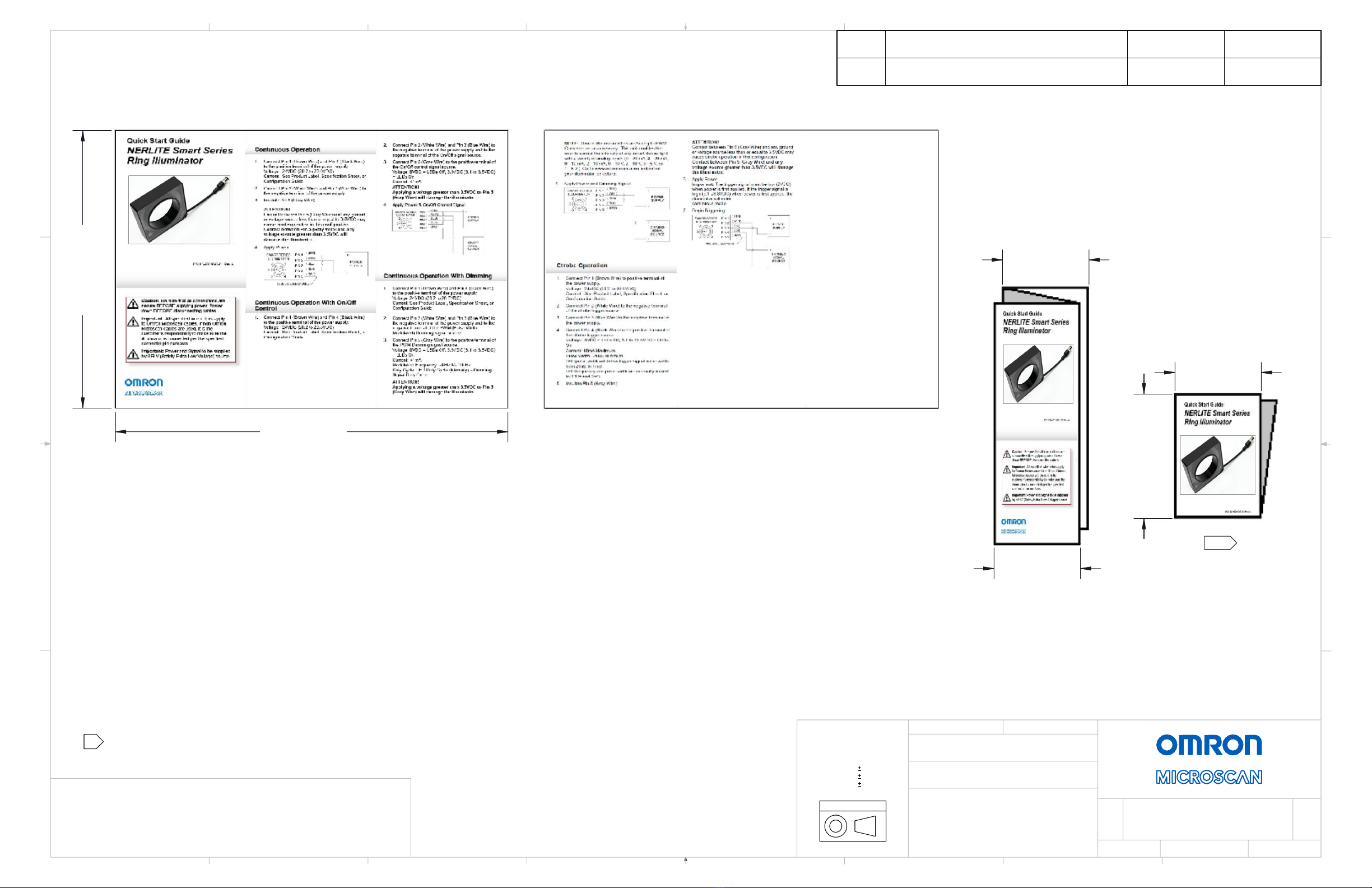
NERLITE Smart Series
Ring Illuminator
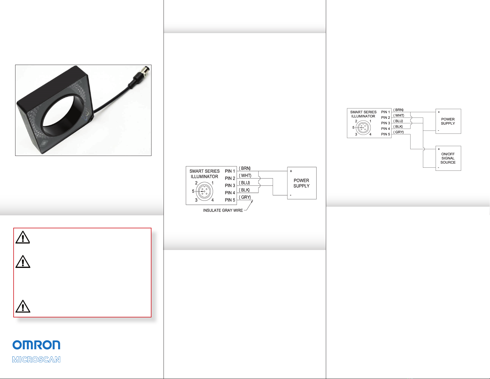
Continuous Operation
1. Connect Pin 1 (Brown Wire) and Pin 4 (Black Wire)
to the positive terminal of the power supply
Voltage: 24VDC (20.2 to 28.8VDC)
Current: See Product Label, Specication Sheet, or
Conguration Guide
2. Connect Pin 2 (White Wire) and Pin 3 (Blue Wire) to
the negative terminal of the power supply.
3. Insulate Pin 5 (Gray Wire)
ATTENTION!
Contact between Pin 5 (Gray Wire) and any ground
or voltage source less than or equal to 3.5VDC may
cause erratic operation in this conguration.
Contact between Pin 5 (Gray Wire) and any
voltage source greater than 3.5VDC will
damage the illuminator.
4. Apply Power
Continuous Operation With On/Off
Control
1. Connect Pin 1 (Brown Wire) and Pin 4 (Black Wire)
to the positive terminal of the power supply.
Voltage: 24VDC (20.2 to 28.8VDC)
Current: See Product Label, Specication Sheet, or
Conguration Guide
2. Connect Pin 2 (White Wire) and Pin 3 (Blue Wire) to
the negative terminal of the power supply and to the
negative terminal of the On/Off signal source.
3. Connect Pin 5 (Gray Wire) to the positive terminal of
the On/Off control signal source.
Voltage: 0VDC = LEDs Off, 3.3VDC (3.1 to 3.5VDC)
= LEDs On
Current: <1mA
ATTENTION!
Applying a voltage greater than 3.5VDC to Pin 5
(Gray Wire) will damage the illuminator.
4. Apply Power & On/Off Control Signal
Continuous Operation With Dimming
1. Connect Pin 1 (Brown Wire) and Pin 4 (Black Wire)
to the positive terminal of the power supply.
Voltage: 24VDC (20.2 to 28.8VDC)
Current: See Product Label, Specication Sheet, or
Conguration Guide
2. Connect Pin 2 (White Wire) and Pin 3 (Blue Wire) to
the negative terminal of the power supply and to the
negative terminal of the PWM (Pulse Width
Modulated) Dimming signal source.
3. Connect Pin 5 (Gray Wire) to the positive terminal of
the PWM Dimming signal source.
Voltage: 0VDC = LEDs Off, 3.3VDC (3.1 to 3.5VDC)
= LEDs On
Current: <1mA
Modulation Frequency: 2KHz +/- 100Hz
Duty Cycle: LED Duty Cycle (Intensity) = Dimming
Signal Duty Cycle
ATTENTION!
Applying a voltage greater than 3.5VDC to Pin 5
(Gray Wire) will damage the illuminator.
Important: All specied wire colors apply
to Omron Microscan cables. If non-Omron
Microscan cables are used, it is the
customer’s responsibility to make sure the
illuminator is connected per the specied
connector pin numbers.
Caution: Be sure that all connections are
secure BEFORE applying power. Power
down BEFORE disconnecting cables.
Important: Power and Signal to be supplied
by SELV (Safety Extra-Low Voltage) source.