ecification
Model number
I
nternal I/O common processing
Number of I/O points
Rated output current
DRT2-OD16
NPN
DRT2-OD16-1
PNP
16 outputs
0.5 A per point, 4.0 A per common
Specification
DRT2-ID16-1 (PNP)
XWT-OD16 (NPN)/OD16 -1 (PNP)
XWT-OD16 (NPN)
DRT2-OD16 (NPN)
DRT2-ID16 (NPN) DRT2-ID16-1 (PNP)DRT2-ID16 (NPN)
DRT2-OD16-1 (PNP)
XWT-ID08 (NPN)/ID08-1 (PNP)
XWT-ID08 (NPN) XWT-ID08-1 (PNP)
XWT-OD16-1 (PNP)
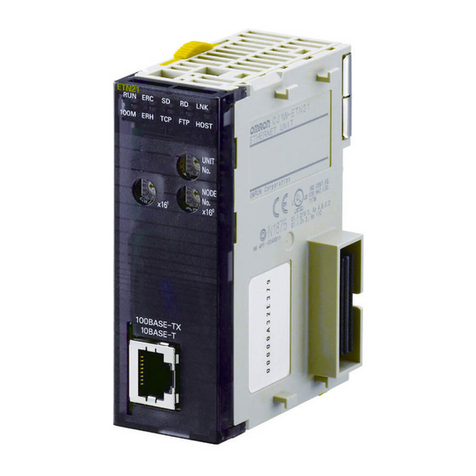
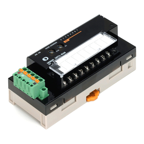
Remote I/O Terminals (Models with 16 Transistor Inputs)
DRT2-ID16 (NPN)/DRT2-ID16-1 (PNP)
Remote I/O Terminals (Models with 16 Transistor Inputs)
DRT2-ID16 (NPN)/DRT2-ID16-1 (PNP)
Remote I/O Terminals (Models with 16 Transistor Outputs)
DRT2-OD16 (NPN)/DRT2-OD16-1 (PNP)
DRT2-OD16 (NPN) DRT2-OD16-1 (PNP)
Remote I/O Terminals (Models with 16 Transistor Outputs)
DRT2-OD16 (NPN)/DRT2-OD16-1 (PNP)
Remote I/O Terminal Expansion Units (Models with 8 Transistor Inputs)
XWT-ID08 (NPN)/ID08-1 (PNP)
XWT-ID08 (NPN) XWT-ID08-1 (PNP)
Remote I/O Terminal Expansion Units (Models with 8 Transistor Inputs)
Remote I/O Terminal Expansion Units (Models with 8 Transistor Outputs)
Remote I/O Terminal Expansion Units (Models with 16 Transistor Inputs)
Remote I/O Terminal Expansion Units (Models with 16 Transistor Outputs)
XWT-OD16 (NPN)/OD16-1 (PNP)
XWT-OD16 (NPN) XWT-OD16 -1 (PNP)
Remote I/O Terminal Expansion Units (Models with 16 Transistor Outputs)
XWT-OD08 (NPN)/OD08-1 (PNP)
XWT-OD08 (NPN) XWT-OD08-1 (PNP)
Remote I/O Terminal Expansion Units (Models with 8 Transistor Outputs)
XWT-OD08 (NPN)/OD08-1 (PNP)
XWT-OD08 (NPN) XWT-OD08-1 (PNP)
XWT-ID16 (NPN)/ID16-1 (PNP)
XWT-ID16 (NPN) XWT-ID16-1 (PNP)
Remote I/O Terminal Expansion Units (Models with 16 Transistor Inputs)
XWT-ID16 (NPN)/ID16-1 (PNP)
XWT-ID16 (NPN) XWT-ID16-1 (PNP)
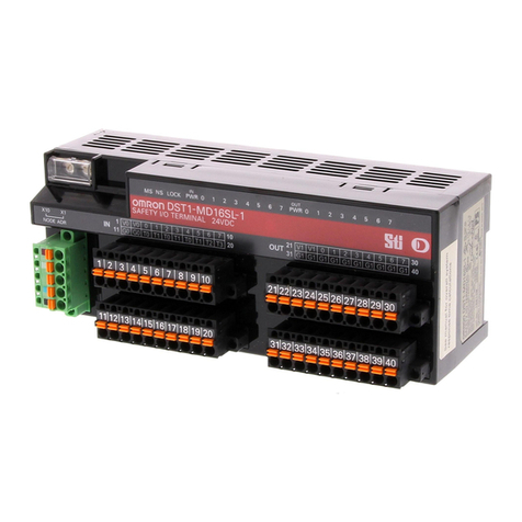
The connector allows easy
checking using a tester.
V 24 VDC
0
1
G
V+
CAN H
DRAIN
CAN L
V–
Photocoupler
Photocoupler
Photocoupler Photocoupler
Photocoupler
Photocoupler
Photocoupler
Photocoupler
Photocoupler
Photocoupler
Photocoupler Photocoupler
Photocoupler
Photocoupler
Photocoupler Photocoupler
Photocoupler
Photocoupler
Photocoupler
Photocoupler
Photocoupler
V 24 VDC
0
1
G
Physical layer
Physical layer
Physical layer
Non-insulated
DC-DC
converter
Non-insulated
DC-DC
converter
Non-insulated
DC-DC
converter
Non-insulated
DC-DC
converter
V+
CAN H
DRAIN
CAN L
V–
0
1
G
V 24 VDC
V+
CAN H
DRAIN
CAN L
V–
V
10
1
11
3
12
5
13
7
14
9
15
G
1
0
2
2
3
4
4
6
5
8
6
24 VDC
Solenoid
11
16
13
17
15
18
10
7
12
8
14
9
Valve
0
1
G
V 24 VDC
V+
CAN H
DRAIN
CAN L
V–
V
10
1
11
3
12
5
13
7
14
9
15
G
1
0
2
2
3
4
4
6
5
8
6
24 VDC
Solenoid
11
16
13
17
15
18
10
7
12
8
14
9
Valve
V 24 VDC
0
1
G
V
6
1
7
3
8
5
9
7
10
G
1
0
2
2
3
4
4
6
5
24 VDC
V 24 VDC
0
1
G
V
6
1
7
3
8
5
9
7
10
G
1
0
2
2
3
4
4
6
5
24 VDC
0
1
G
V 24 VDC
V
6
1
7
3
8
5
9
7
10
G
1
0
2
2
3
4
4
6
5
24 VDC
0
1
G
V 24 VDC
V
6
1
7
3
8
5
9
7
10
G
1
0
2
2
3
4
4
6
5
24 VDC
V 24 VDC
0
1
G
V
10
1
11
3
12
5
13
7
14
9
15
G
1
0
2
2
3
4
4
6
5
8
6
24 VDC
11
16
13
17
15
18
10
7
12
8
14
9
V 24 VDC
0
1
G
0
1
G
V 24 VDC V
10
1
11
3
12
5
13
7
14
9
15
G
1
0
2
2
3
4
4
6
5
8
6
24 VDC
11
16
13
17
15
18
10
7
12
8
14
9
0
1
G
V 24 VDC
V
10
1
11
3
12
5
13
7
14
9
15
G
1
0
2
2
3
4
4
6
5
8
6
24 VDC
11
16
13
17
15
18
10
7
12
8
14
9
V
10
1
11
3
12
5
13
7
14
9
15
G 0 2
3
4
4
6
5
8
6
24 VDC
11
16
13
17
15
18
10
7
12
8
14
9
12
V
10
1
11
3
12
5
13
7
14
9
15
G
1
0
2
2
3
4
4
6
5
8
6
24 VDC
11
16
13
17
15
18
10
7
12
8
14
9
V
10
1
11
3
12
5
13
7
14
9
15
G 0 2
3
4
4
6
5
8
6
24 VDC
I/O power supply
I/O power supply
I/O power supply
I/O power supply
I/O power supply
I/O power supply I/O power supply
I/O power supply
I/O power supply
I/O power supply
I/O power supply
I/O power supply
Three-wire sensor with
NPN output
(photoelectric sensor or
proximity sensor)
Two-wire sensor
(e.g., limit switch)
Three-wire sensor with
NPN output
(photoelectric sensor or
proximity sensor)
Two-wire sensor
(e.g., limit switch)
+–
+–
+–
+–
+–
+– +–
+–
+–
+–
+–
+–
11
16
13
17
15
18
10
7
12
8
14
9
12
C
a
u
s
e
s
f
o
r
c
o
mm
un
i
ca
t
i
on
e
rr
o
r
s
ca
n
b
e
m
on
i
t
o
r
e
d
.
C
ommuni
c
a
tion
E
rr
o
r
H
i
s
to
r
y
M
onito
r
F
un
c
tion
R
e
c
o
r
d
e
d
in
th
e
S
l
ave
S
m
a
ll
e
s
t
in
I
t
s
C
l
a
ss
The width of the Basic Unit is 115 mm (77% of 150-mm
DRT1-series models) and the width of the Expansion Unit is
94 mm, giving a total expanded width of 209 mm, making it
the smallest device of its class in the industry.
S
c
r
e
w
-
l
e
ss
C
l
a
mp
C
ommuni
c
a
tion
s
C
onn
e
c
to
r
s
E
a
s
y
E
x
p
a
n
s
ion
with
E
x
p
a
n
s
ion
U
nit
s
The Smart Slaves can be expanded easily by freely
combining Expansion Units with Basic Units using snap-on
mounting. This means less wiring work is required.
I
nput
F
ilt
e
r
F
un
c
tion
The influence of noise can be removed using the ON
response time. Also, very small pulses that are shorter
than the communications time can be handled using the
OFF response time.
F
un
c
tion
f
o
r
H
a
ndling
S
e
n
s
o
r
I
n
r
u
s
h
C
u
rr
e
nt
In order to prevent incorrect input due to inrush current
when, for example, power to a sensor is turned ON, the
Slave can be set not to accept input for 100 ms after the
input power supply is turned ON.
E
a
s
y
M
ounting
a
nd
D
i
s
mounting
o
f
T
e
r
min
a
l
B
lo
c
k
s
Terminal blocks can
be mounted and
dismounted with
ease.
B
a
s
i
c
F
un
c
tion
s
A
l
s
o
I
mp
r
o
ve
d
Wiring can be performed by
inserting post terminals.
G
e
n
e
r
a
l
S
p
e
c
i
f
i
c
a
tion
s
I
nt
e
r
n
a
l
C
i
r
c
uit
D
i
a
g
r
a
m
s
W
i
r
ing
D
i
a
g
r
a
m
s
I
nput
S
p
e
c
i
f
i
c
a
tion
s
O
ut
