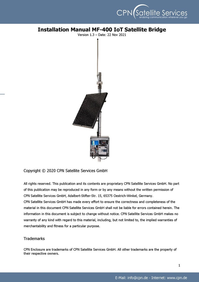
CPN MF-500 User manual

1
Installation Manual MF-500 IoT Satellite Bridge
Version 1.1 –Date: 17 Aug 2021
Copyright © 2021 CPN Satellite Services GmbH
All rights reserved. This publication and its contents are proprietary CPN Satellite Services GmbH. No part
of this publication may be reproduced in any form or by any means without the written permission of
CPN Satellite Services GmbH, Adalbert-Stifter-Str. 15, 65375 Oestrich-Winkel, Germany.
CPN Satellite Services GmbH has made every effort to ensure the correctness and completeness of the
material in this document CPN Satellite Services GmbH shall not be liable for errors contained herein. The
information in this document is subject to change without notice. CPN Satellite Services GmbH makes no
warranty of any kind with regard to this material, including, but not limited to, the implied warranties of
merchantability and fitness for a particular purpose.
Trademarks
CPN Enclosure are trademarks of CPN Satellite Services GmbH. All other trademarks are the property of
their respective owners.

2
Contents
Preliminary note ............................................................................................................................3
Safety Instructions........................................................................................................................3
Terminology and Abbreviations ..................................................................................................3
Required Tools...............................................................................................................................3
Technical overview .......................................................................................................................4
1. Mount the CPN Enclosure to the pole ................................................................................5
2. Mount the antenna to the pole............................................................................................6
3. Mount the IDP-Terminal to the pole...................................................................................7
4. Open the CPN Enclosure ......................................................................................................8
5. Ensure all circuit breakers are switched off / not plugged in......................................9
6. Insert the antenna cable and connect it ..........................................................................10
7. Switch on / plug in all circuit breakers inside the Enclosure ........................................11
8. Check if the system is operating properly .......................................................................12
9. Close the CPN Enclosure ....................................................................................................13
Any questions or suggestions? .................................................................................................14

3
Preliminary note
Please read manuals of the installed systems to make sure that all safety requirements are fulfilled at any
time.
Safety Instructions
An external fuse or circuit breaker (max. 20A) must be provided in the onsite installation as
an interrupt facility for the Enclosure system. –Only applicable for AC powered systems!
WARNING Risk of electrical shock, fire, personal injury or death.
➢Do not use a power supply without proper grounding (Protective Earth). Use the terminal on the
input block for earth connection. Make sure that protective earth is connected according to all
local and national codes and regulations!
➢Turn power off before working on the device. Protect against inadvertent re-powering.
➢Make sure that the wiring is correct by following all local and national codes.
➢Do not modify or repair the unit.
➢Do not open the electronic units, e.g. power supply, as high voltages are present inside.
➢Use caution to prevent any foreign objects from entering into the housing.
➢Do not use in wet locations or in areas where moisture or condensation can be expected while
cover is not mounted.
➢Do not touch during power-on, and immediately after power-off. Hot surface may cause burns.
Terminology and Abbreviations
PE PE is the abbreviation for Protective Earth and has the same meaning as the symbol.
Earth, Ground This document uses the term “earth” which is the same as the U.S. term “ground”.
T.B.D. To be defined, value or description will follow later.
AC 230V A figure displayed with the AC or DC before the value represents a nominal voltage with
standard tolerances (usually ±15%) included.
E.g.: DC 12V describes a 12V battery disregarding whether it is full (13.7V) or flat (10V)
230Vac A figure with the unit (Vac) at the end is a momentary figure without any additional
tolerances included.
50Hz vs. 60Hz As long as not otherwise stated, AC 100V and AC 230V parameters are valid at 50Hz and
AC 120V parameters are valid at 60Hz mains frequency.
may A key word indicating flexibility of choice with no implied preference.
shall A key word indicating a mandatory requirement.
should A key word indicating flexibility of choice with a strongly preferred implementation.
DCE data communication equipment
DTE data terminal equipment
Required Tools
•Phillips screwdriver PH3 enclosure lid
•Slotted screwdriver 0.6x3.5mm terminal blocks
•Wrench #8 pole mount enclosure & IDP terminal
•Wrench #10 LoRaWAN antenna
•Zip ties
•Wire cutter

4
Technical overview
The MF 500 IoT Satellite Bridge provides network server connectivity for up to 100 remote LoRaWAN™
sensors via Inmarsat IsatDataPro (IDP) satellite terminals and is designed to operate with 110 to 240 AC
mains.
The MF 500 runs an optimized protocol to ensure that airtime satellite costs per sensor are kept to a
minimum. This makes the MF 500 IoT Satellite Bridge a standalone, low power, low cost solution for
adding satellite connectivity to your existing COTS LoRaWAN™ sensor devices.
The MF 500 IoT Satellite Bridge supports LoRaWAN™ version 1.0.2. The MF 500 IoT Satellite Bridge is
compatible with a very wide range of commercial off the shelf (COTS) LoRaWAN™ sensors.
Both the MF-200 LoRaWAN Gateway and the power supply are installed in IP67 rated CPN enclosures for
harsh environments.

5
1. Mount the CPN Enclosure to the pole
Mount the Enclosure to the pole by using the pole mount located at the backside of the Enclosure.

6
2. Mount the antenna to the pole
Plug the antenna cable into the antenna and use its pole mount to secure it onto the top of the pole.
Please make sure that your installation matches antenna cable requirements!

7
3. Mount the IDP-Terminal to the pole
Plug the IDP cable into the IDP terminal and use its pole mount to secure it onto the Pole.
We recommend using zip ties to fix the cables to the pole.
Please make sure that your installation matches cable requirements!

8
4. Open the CPN Enclosure
Loosen the 4 marked screws of the cover and remove it from the Enclosure

9
5. Ensure all circuit breakers are switched off
Make sure all circuit breakers are switched off and pointing down.

10
6. Insert the antenna cable and connect it
Insert the antenna cable into Enclosure and connect to the connector located on the bottom left of the
MF 200 (RF).
(depending on the cable you might need to use an SMA adapter)

11
7. Switch on all circuit breakers inside the Enclosure
Connect the AC Power Cable to the main 110 to 240 V AC power source.
Switch on all circuit breakers.

12
8. Check if the system is operating properly
Check if the LED on the power supply and MF-200 LoRaWAN Gateway glows green.
Please check whether data form the MF-200 LoRaWAN Gateway are received by the MinFarm Portal
properly.

13
9. Close the CPN Enclosure
Screw in the 4 marked screws of the cover to reinstall it to the Enclosure.
Table of contents
Other CPN Network Hardware manuals

