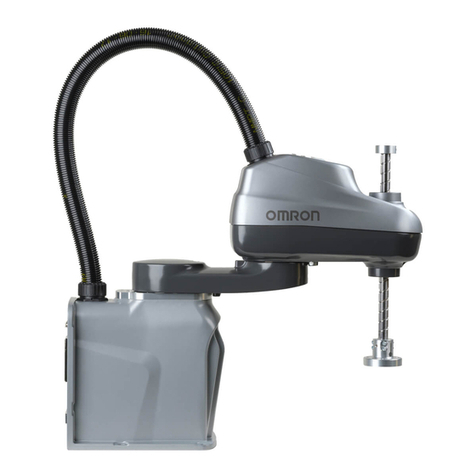
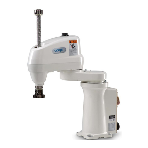
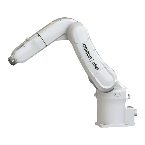
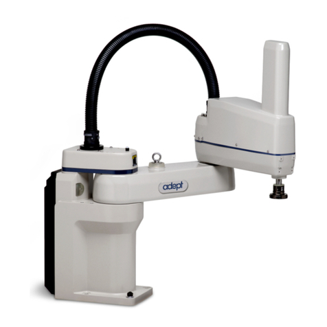
Omron SCARA R6Y-XC Series User manual

ZX-T Series
Cat. No. I144E-EN-01
R6Y - XC series
USER´S MANUAL
Cat. No. I144E-EN-01 Note: Specifications subject to change without notice.
Authorized Distributor:
Printed in Europe
Cat. No. I144E-EN-01 SCARA Robot, R6Y - XC series USERS MANUAL
SCARA Robots
XC Series


Before using the robot
(Be sure to read the following notes.)
At this time, our thanks for your purchase of this OMRON XC series SCARA
robot.
1.
Please be sure to perform the following tasks before using the robot.
Failing to perform the tasks below will require re-teaching of the robot since
the origin position cannot be set to the same previous position. Robot malfunc-
tions (vibration, noise) may also occur.
The origin position of the XC series robots is adjusted to the robot arm exten-
ded position at the factory prior to shipment, so the reference or standard coor-
dinates are temporarily set.
The customer should set the origin position before any other job. There are 2
types of origin position settings as shown below.
[1] Setting the robot arm extended position (the origin position adjusted at the
factory prior to shipment) as the origin position
(When setting the origin position with the robot arm extended, you must
check that there will not be any interference from any peripheral equip-
ment during the next absolute reset.)
[2] Setting a position OTHER than the robot arm extended position (the ori-
gin position adjusted at the factory prior to shipment) as the origin position
[1] To set the robot arm extended position (the origin position adjusted at the
factory prior to shipment) as the origin position.
Absolute Reset
The XC series robots only require the absolute reset to be performed once
when the robot is introduced.
Once the absolute reset is performed, you do not need to reperform it when
the power is turned on next time.
Set the origin position while referring to absolute reset methods in "3. Ad-
justing the origin" in Chapter 4 of this manual and in "Absolute Reset" of
the "OMRON Robot Controller User's Manual". Setting of reference coordi-
nates is not required in the above case.
CAUTION
NEVER ENTER THE ROBOT MOVEMENT RANGE ONCE THE ROBOT
SERVO IS TURNED ON AS THIS IS EXTREMELY HAZARDOUS.

[2] To set a position OTHER than the robot arm extended position (the origin
position adjusted at the factory prior to shipment) as the origin position.
1. Absolute reset
The XC series robots only require the absolute reset to be performed once
when the robot is introduced.
Once the absolute reset is performed, you do not need to reperform it when
the power is turned on next time.
Set the origin position while referring to absolute reset methods in "3. Ad-
justing the origin" in Chapter 4 of this manual and in "Absolute Reset" of
the "OMRON Robot Controller User's Manual".
Set the origin position with the absolute reset.
2. Afxing the origin position sticker
Set in emergency stop when absolute reset is complete, and immediately
afx the origin point sticker according to instructions in "6. Afxing Stick-
ers for Origin Positions, Movement Directions and Axis Names" in Chapter
4 of this manual.
3. Setting the reference coordinates
Set the reference coordinates while referring to instructions in "5. Setting the
Reference Coordinates" in Chapter 4 of this manual and also to "Setting the
Reference Coordinates" in the "OMRON Robot Controller User's Manual".
Robot malfunctions (vibration, noise) may occur if the reference coordinates
are not set correctly.
Even though there is no problem with the robot, the following error messages
are issued when the robot and controller are connected and power rst turned
on.
(Actual error messages may differ according to how the robot and controller
are connected.)
Error messages issued when robot & controller are connected (YRC)
17.81 : D?.ABS.battery wire breakage
17.83 : D?.Backup position data error 1
17.85 : D?.Backup position data error 2
17.92 : D?.Resolver disconnected during power off
17.93 : D?.Position backup counter overow
etc.
2. If the X, Y or R axis rotation angle is small.
If the X, Y or R axis rotation angle is smaller than 5° so that it always moves in
the same position, an oil lm is difcult to be formed on the joint support bear-
ing, possibly leading to damage to the bearing. In this type of operation, add a
movement so that the joint moves through 90° or more, about 5 times a day.
CAUTION
NEVER ENTER THE ROBOT MOVEMENT RANGE ONCE THE ROBOT
SERVO IS TURNED ON AS THIS IS EXTREMELY HAZARDOUS.
Copyright
The following shall be described in the Copyright section and the description
shall not be changed without permission.
OMRON, 2010
All rights reserved. No part of this publication may be reproduced, stored in
a retrieval system, or transmitted, in any form, or by any means, mechanical,
electronic, photocopying, recording, or otherwise, without the prior written per-
mission of OMRON.
No patent liability is assumed with respect to the use of the information con-
tained herein. Moreover, because OMRON is constantly striving to improve
its high-quality products, the information contained in this manual is subject
to change without notice. Every precaution has been taken in the preparation
of this manual. Nevertheless, OMRON assumes no responsibility for errors or
omissions. Neither is any liability assumed for damages resulting from the use
of the information contained in this publication.
Introduction
This user’s manual was prepared for XC series ceiling-mount models
(R6YXCH250 to R6YXC1000) of the OMRON industrial robots.
This user’s manual describes the safety measures, handling, adjustment and
maintenance of XC series robots for correct, safe and effective use. Be sure to
read this manual carefully before installing the robot. Even after you have read
this manual, keep it in a safe and convenient place for future reference.
This user’s manual should be used with the robot and considered an integral
part of it. When the robot is moved, transferred or sold, send this manual to the
new user along with the robot. Be sure to explain to the new user the need to
read through this manual.
For the operating or maintenance procedures not described in this manual,
please refer to the description of standard models listed in the "OMRON
SCARA Robot User's Manual". Also refer to that manual for precautions and
warranty. If there are any obscure points in handling the robot, be sure to
contact OMRON sales ofce or dealer.
For details on specific operation and programming of the robot, refer to the
separate “OMRON Robot Controller User’s Manual”.

Disclaimers
CHANGE IN SPECIFICATIONS
Product specications and accessories may be changed at any time based on improvements
and other reasons. It is our practice to change model numbers when published ratings or
features are changed, or when significant construction changes are made. However, some
specications of the products may be changed without any notice. When in doubt, special
model numbers may be assigned to x or establish key specications for your application on
your request. Please consult with your OMRON representative at any time to conrm actual
specications of purchased products.
DIMENSIONS AND WEIGHTS
Dimensions and weights are nominal and are not to be used for manufacturing purposes, even
when tolerances are shown.
PERFORMANCE DATA
Performance data given in this manual is provided as a guide for the user in determining
suitability and does not constitute a warranty. It may represent the result of OMRON’s
test conditions, and the users must correlate it to actual application requirements. Actual
performance is subject to the OMRON Warranty and Limitations of Liability.
ERRORS AND OMISSIONS
The information in this manual has been carefully checked and is believed to be accurate;
however, no responsibility is assumed for clerical, typographical, or proofreading errors, or
omissions.

CONTENTS
CHAPTER 1 Using the Robot Safely
1 Safety Information ........................................................................ 1-1
2 Essential Caution Items ................................................................ 1-2
3 Special Training for Industrial Robot Operation .......................... 1-8
4 Robot Safety Functions................................................................. 1-9
5 Safety Measures for the System ................................................. 1-10
6 Trial Operation ............................................................................ 1-11
7 Work Within the Safeguard Enclosure ........................................ 1-12
8 Automatic Operation .................................................................. 1-13
9 Adjustment and Inspection ......................................................... 1-13
10 Repair and Modication ............................................................. 1-13
11 Warranty...................................................................................... 1-14
12 CE Marking ................................................................................ 1-16
CHAPTER 2 Functions
1 Robot Manipulator ........................................................................ 2-1
2 Robot Controller ........................................................................... 2-5
CHAPTER 3 Installation
1 Robot Installation Conditions ....................................................... 3-1
1-1 Installation environments ........................................................................ 3-1
1-2 Installation base ...................................................................................... 3-3
2 Installation .................................................................................... 3-5
2-1 Unpacking ............................................................................................... 3-5
2-2 Checking the product .............................................................................. 3-6
2-3 Moving the robot..................................................................................... 3-7
2-3-1 Moving the R6YXCH250, R6YXCH350, R6YXCH400 .................................... 3-7
2-3-2 Moving the R6YXC500, R6YXC600, R6YXC700, R6YXC800, R6YXC1000 3-8
2-4 Installing the robot ................................................................................ 3-11
3 Protective Bonding ..................................................................... 3-12
4 Robot Cable Connection ............................................................. 3-14

5 User Wiring and User Tubing ..................................................... 3-16
6 Attaching The End Effector ........................................................ 3-20
6-1
R-axis tolerable moment of inertia and acceleration coefcient
............. 3-20
6-1-1 Acceleration coefcient vs. moment of inertia (R6YXCH250) ........................ 3-22
6-1-2 Acceleration coefcient vs. moment of inertia (R6YXCH350) ........................ 3-23
6-1-3 Acceleration coefcient vs. moment of inertia (R6YXCH400) ........................ 3-24
6-1-4 Acceleration coefcient vs. moment of inertia (R6YXC500) ........................... 3-25
6-1-5 Acceleration coefcient vs. moment of inertia (R6YXC600) ........................... 3-28
6-1-6 Acceleration coefcient vs. moment of inertia (R6YXC700) ........................... 3-31
6-1-7 Acceleration coefcient vs. moment of inertia (R6YXC800) ........................... 3-36
6-1-8 Acceleration coefcient vs. moment of inertia (R6YXC1000) ......................... 3-41
6-2 Equation for moment of inertia calculation .......................................... 3-46
6-3 Example of moment of inertia calculation ............................................ 3-46
6-4 Attaching the end effector ..................................................................... 3-47
6-5 Gripping force of end effector .............................................................. 3-51
7 Limiting the Movement Range with X-Axis Mechanical Stoppers
(Excluding R6YXCH250, R6YXCH350, R6YXCH400) ......... 3-52
8 Working Envelope and Mechanical Stopper Positions for
Maximum Working Envelope ..................................................... 3-55
CHAPTER 4 Adjustment
1 Overview....................................................................................... 4-1
2 Safety Precautions ........................................................................ 4-1
3 Adjusting the origin ...................................................................... 4-2
3-1 Absolute reset method............................................................................. 4-2
3-2 Machine reference ................................................................................... 4-2
3-3 Absolute reset procedures ....................................................................... 4-2
3-4
Changing the origin position and adjusting the machine reference
.............. 4-2
3-4-1 Sensor method ...................................................................................................... 4-2
3-4-2 Mark method ........................................................................................................ 4-2
3-4-3 Stroke end method ............................................................................................... 4-3
4 Setting the Soft Limits .................................................................. 4-6
5 Setting the Standard Coordinates.................................................. 4-8
6 Afxing Stickers for Origin Positions,
Movement Directions and Axis Names ........................................ 4-9
7 Removing the Robot Covers ....................................................... 4-11

8 Adjusting the Timing Belt Tension ............................................. 4-15
8-1
Adjusting the belt tension (R6YXCH250, R6YXCH350, R6YXCH400)
........ 4-16
8-2 Adjusting the belt tension (R6YXC500, R6YXC600) ......................... 4-18
8-3 Adjusting the belt tension (R6YXC700, R6YXC800, R6YXC1000) .. 4-20
CHAPTER 5 Periodic Inspecition
1 Overview....................................................................................... 5-1
2 Precautions .................................................................................... 5-2
3 Daily Inspection ............................................................................ 5-3
4 Six-Month Inspection ................................................................... 5-5
5 Replacing the Harmonic Drive ..................................................... 5-8
5-1 Replacement period ................................................................................ 5-8
5-2
Basic replacement procedure for harmonic drive and precautions
.............. 5-9
5-2-1 R6YXCH250, R6YXCH350, R6YXCH400 ..................................................... 5-11
5-2-2 R6YXC500, R6YXC600 ................................................................................... 5-27
5-2-3 R6YXC700, R6YXC800, R6YXC1000 ............................................................ 5-42
6 Replacing the bellows ................................................................. 5-59
CHAPTER 6 Specications
1 Manipulator................................................................................... 6-1
1-1 Basic specication .................................................................................. 6-1
1-2 Robot inner wiring diagram .................................................................... 6-4
1-3 Wiring table ............................................................................................. 6-6


CHAPTER 1
Using the Robot Safely
1 Safety Information .............................................................................1-1
2 Essential Caution Items ......................................................................1-2
3 Special Training for Industrial Robot Operation ................................1-8
4 Robot Safety Functions ......................................................................1-9
5 Safety Measures for the System .......................................................1-10
6 Trial Operation ................................................................................. 1-11
7 Work Within the Safeguard Enclosure .............................................1-12
8 Automatic Operation ........................................................................1-13
9 Adjustment and Inspection ...............................................................1-13
10 Repair and Modication ...................................................................1-13
11 Warranty ...........................................................................................1-14
12 CE Marking ......................................................................................1-16


1-1
CHAPTER 1 Using the Robot Safely
1 Safety Information
Industrial robots are highly programmable, mechanical devices that provide
a large degree of freedom when performing various manipulative tasks. To
ensure correct and safe use of OMRON industrial robots, carefully read this
manual and make yourself well acquainted with the contents. FOLLOW THE
WARNINGS, CAUTIONS AND INSTRUCTIONS INCLUDED IN THIS
MANUAL. Failure to take necessary safety measures or mishandling due to not
following the instructions in this manual may result in trouble or damage to the
robot and injury to personnel (robot operator or service personnel) including
fatal accidents.Warning information in this manual is shown classied into the
following items.
Refer to the instruction manual by any of the following methods to operate or
adjust the robot safely and correctly.
1. Operate or adjust the robot while referring to the printed version of the
instruction manual (available for an additional fee).
2. Operate or adjust the robot while viewing the CD-ROM version of the
instruction manual on your computer screen.
3. Operate or adjust the robot while referring to a printout of the necessary
pages from the CD-ROM version of the instruction manual.
It is not possible to detail all safety items within the limited space of this
manual. So it is essential that the user have a full knowledge of basic safety
rules and also that the operator makes correct judgments on safety procedures
during operation. This manual and warning labels supplied with or afxed to
the robot are written in English.
DANGER
FAILURE TO FOLLOW DANGER INSTRUCTIONS WILL RESULT IN
SEVERE INJURY OR DEATH TO THE ROBOT OPERATOR, A BYSTANDER
OR A PERSON INSPECTING OR REPAIRING THE ROBOT.
ADDITIONALLY, THERE MAY BE SEVERE PROPERTY DAMAGE.
WARNING
FAILURE TO FOLLOW WARNING INSTRUCTIONS COULD RESULT IN
SEVERE INJURY OR DEATH TO THE ROBOT OPERATOR, A BYSTANDER
OR A PERSON INSPECTING OR REPAIRING THE ROBOT.
ADDITIONALLY, THERE MAY BE SEVERE PROPERTY DAMAGE..
CAUTION
FAILURE TO FOLLOW CAUTION INSTRUCTIONS MAY RESULT IN
INJURY TO THE ROBOT OPERATOR, A BYSTANDER OR A PERSON
INSPECTING OR REPAIRING THE ROBOT, OR DAMAGE TO THE ROBOT
AND/OR ROBOT CONTROLLER.
NOTE
Explains the key point in the operation in a simple and clear manner.

1-2
CHAPTER 1 Using the Robot Safely
2 Essential Caution Items
Particularly important cautions for handling or operating the robot are
described below. In addition, safety information about installation, operation,
inspection and maintenance is provided in each chapter. Be sure to comply with
these instructions to ensure safe use of the robot.
(1) Observe the following cautions during automatic operation.
Warning labels 1 (Fig. 1-1) are afxed to the robot. See Fig. 2-2 to Fig. 2-4
for the locations of warning labels.
• Install a safeguard enclosure (protective enclosure) to keep any person
from entering within the movement range of the robot and suffering
injury due to being struck by moving parts.
• Install a safety interlock that triggers emergency stop when the door or
panel is opened.
• Install safeguards so that no one can enter inside except from doors or
panels equipped with safety interlocks.
• The warning labels shown in Fig. 1-1 are supplied with the robot and
should be afxed to a conspicuous spot on doors or panels equipped with
safety interlocks.
(2) Use caution to prevent hands or fingers from being pinched or
crushed.
Warning labels 2 (Fig. 1-2) are afxed to the robot. See Fig. 2-2 to Fig. 2-4
for the locations of warning labels.
Be careful not to let hands or ngers be pinched or crushed by the moving
parts of the robot during transportation or teaching.
DANGER
Serious injury or death
will result from impact
with moving robot.
• Keep outside of guard
during operation.
• Lock out power before
approaching robot.
Moving parts can
pinch or crush.
Keep hands away
from robot arms.
WARNING
■Fig. 1-1 Warning label 1 ■Fig. 1-2 Warning label 2
DANGER
SERIOUS INJURY OR DEATH WILL RESULT FROM IMPACT WITH
MOVING ROBOT.
• KEEP OUTSIDE OF GUARD DURING OPERATION.
• LOCK OUT POWER BEFORE APPROACHING ROBOT.
WARNING
MOVING PARTS CAN PINCH OR CRUSH.
KEEP HANDS AWAY FROM ROBOT ARMS.

1-3
CHAPTER 1 Using the Robot Safely
(3) Follow the instructions on warning labels and in this manual.
Warning label 3 (Fig. 1-3) is afxed to the robot. See Fig. 2-2 to Fig. 2-4
for the locations of warning labels.
• Be sure to read the warning label and this manual carefully and make
you thoroughly understand the contents before attempting installation
and operation of the robot.
• Before starting the robot operation, even after you have read through this
manual, read again the corresponding procedures and cautions in this
manual as well as descriptions in this chapter (Chapter 1, “Using the Ro-
bot Safely”).
• Never install, adjust, inspect or service the robot in any manner that does
not comply with the instructions in this manual.
■Fig. 1-3 Warning label 3
(4) Do not use the robot in environments containing inammable gas, etc.
(5) Do not use the robot in locations possibly subject to electromagnetic
interference, etc.
Improper Installation or operation can
result in serious injury or death.
Read user's (owner's) manual and all
warning labels before operation.
WARNING
WARNING
IMPROPER INSTALLATION OR OPERATION CAN RESULT IN SERIOUS
INJURY OR DEATH.
READ USER’S MANUAL AND ALL WARNING LABELS BEFORE
OPERATION.
WARNING
• THIS ROBOT WAS NOT DESIGNED FOR OPERATION IN
ENVIRONMENTS WHERE INFLAMMABLE OR EXPLOSIVE SUBSTANCES
ARE PRESENT.
• DO NOT USE THE ROBOT IN ENVIRONMENTS CONTAINING
INFLAMMABLE GAS, DUST OR LIQUIDS. EXPLOSIONS OR FIRE COULD
OTHERWISE RESULT.
WARNING
AVOID USING THE ROBOT IN LOCATIONS SUBJECT TO
ELECTROMAGNETIC INTERFERENCE, ELECTROSTATIC DISCHARGE
OR RADIO FREQUENCY INTERFERENCE. MALFUNCTION MAY
OTHERWISE OCCUR.

1-4
CHAPTER 1 Using the Robot Safely
(6) Use caution when releasing the Z-axis (vertical axis) brake.
(7) Provide safety measures for end effector (gripper, etc.).
(8) Be cautious of possible Z-axis movement when the controller is turned
off or emergency stop is triggered. (2-axis robots with air-driven Z-
axis)
(9) Use the following caution items when the Z-axis is interfering with
peripheral equipment. (2-axis robots with air driven Z-axis)
WARNING
THE Z-AXIS WILL SLIDE DOWN WHEN THE Z-AXIS BRAKE IS
RELEASED, CAUSING A HAZARDOUS SITUATION.
• PRESS THE EMERGENCY STOP BUTTON AND PROP UP THE Z-AXIS
WITH A SUPPORT STAND BEFORE RELEASING THE BRAKE.
• USE CAUTION NOT TO LET YOUR BODY GET CAUGHT BETWEEN THE
Z-AXIS AND INSTALLATION BASE WHEN RELEASING THE BRAKE TO
PERFORM DIRECT TEACH.
WARNING
• END EFFECTORS MUST BE DESIGNED AND MANUFACTURED SO
THAT THEY CAUSE NO HAZARDS (FOR EXAMPLE, LOOSENING OF
WORKPIECE) EVEN IF POWER (ELECTRICITY, AIR PRESSURE, ETC.) IS
SHUT OFF OR POWER FLUCTUATIONS OCCUR.
• IF THERE IS A POSSIBLE DANGER THAT THE OBJECT GRIPPED BY
THE END EFFECTOR MAY FLY OFF OR DROP, THEN PROVIDE
APPROPRIATE SAFETY PROTECTION TAKING INTO ACCOUNT THE
OBJECT SIZE, WEIGHT, TEMPERATURE AND CHEMICAL PROPERTIES.
WARNING
THE Z-AXIS MOVES UP WHEN THE POWER TO THE CONTROLLER OR
PLC IS TURNED OFF, THE PROGRAM IS RESET, EMERGENCY STOP IS
TRIGGERED, OR AIR IS SUPPLIED TO THE SOLENOID VALVE FOR THE
Z-AXIS AIR CYLINDER.
• DO NOT LET HANDS OR FINGERS GET CAUGHT AND SQUEEZED BY
MOVING PARTS OF THE Z-AXIS.
• KEEP THE USUAL ROBOT POSITION IN MIND SO THAT THE Z-AXIS
WILL NOT INTERFERE WITH OBSTACLES DURING RAISING OF THE
Z-AXIS, EXCEPT IN CASE OF EMERGENCY STOP.
WARNING
WHEN THE Z-AXIS COMES TO A STOP DUE TO OBSTRUCTIONS FROM
PERIPHERAL EQUIPMENT, THE Z-AXIS MAY MOVE SUDDENLY WHEN
THE OBSTRUCTION IS REMOVED, CAUSING INJURY SUCH AS
PINCHED OR CRUSHED HANDS.
• TURN OFF THE CONTROLLER AND REDUCE THE AIR PRESSURE
BEFORE ATTEMPTING TO REMOVE THE OBSTRUCTION.
•BEFORE REDUCING THE AIR PRESSURE, PLACE A SUPPORT STAND
UNDER THE Z-AXIS BECAUSE IT WILL DROP UNDER ITS OWN
WEIGHT.

1-5
CHAPTER 1 Using the Robot Safely
(10) Use caution on Z-axis movement when air supply is stopped. (2-axis
robots with air-driven Z-axis)
(11) Use the following caution items when disassembling or replacing the
pneumatic equipment.
(12) Use the following caution items when removing the Z-axis motor.
(13) Use the following caution during inspection of controller.
For precautions on handling the controller, refer to the "OMRON Robot
Controller User's Manual".
WARNING
THE Z-AXIS MAY SUDDENLY DROP WHEN THE AIR PRESSURE TO THE
Z-AXIS AIR CYLINDER SOLENOID VALVE IS REDUCED, CREATING A
HAZARDOUS SITUATION.
TURN OFF THE CONTROLLER AND PLACE A PROP OR SUPPORT
UNDER THE Z-AXIS BEFORE CUTTING OFF THE AIR SUPPLY.
WARNING
AIR OR PARTS MAY FLY OUTWARDS IF PNEUMATIC EQUIPMENT IS
DISASSEMBLED OR PARTS REPLACED WHILE AIR IS STILL SUPPLIED.
• DO SERVICE WORK AFTER FIRST TURNING OFF THE CONTROLLER
AND REDUCING THE AIR PRESSURE.
• BEFORE REDUCING THE AIR PRESSURE, PLACE A SUPPORT STAND
UNDER THE Z-AXIS (2-AXIS ROBOTS WITH AIR DRIVEN Z-AXIS)
SINCE IT WILL DROP UNDER ITS OWN WEIGHT.
WARNING
THE Z-AXIS WILL DROP WHEN THE Z-AXIS MOTOR IS REMOVED,
POSSIBLY RESULTING IN INJURY.
• TURN OFF THE CONTROLLER AND SET A SUPPORT STAND UNDER
THE Z-AXIS BEFORE REMOVING THE MOTOR.
• USE CAUTION NOT TO ALLOW HANDS OR BODY TO BE SQUEEZED
OR CRUSHED BY MOVING PARTS ON THE Z-AXIS OR BETWEEN THE
Z-AXIS AND THE INSTALLATION BASE.
WARNING
• WHEN YOU NEED TO TOUCH THE TERMINALS OR CONNECTORS ON
THE OUTSIDE OF THE CONTROLLER DURING INSPECTION, ALWAYS
FIRST TURN OFF THE CONTROLLER POWER SWITCH AND ALSO THE
POWER SOURCE IN ORDER TO PREVENT POSSIBLE ELECTRICAL
SHOCK.
• NEVER TOUCH ANY INTERNAL PARTS OF THE CONTROLLER.

1-6
CHAPTER 1 Using the Robot Safely
(14) Consult us for corrective action when the robot is damaged or mal-
function occurs.
Damage or Trouble Possible Danger
Damage to machine harness or robot cable Electrical shock, malfunction of robot
Damage to exterior of robot Flying outwards of damaged parts during
robot operation
Abnormal operation of robot
(positioning error, excessive vibration, etc.) Malfunction of robot
Z-axis brake trouble Dropping of load
(15) Use caution not to touch the controller rear panel cooling fan.
(16) Use caution not to touch the high temperature motor or speed reduc-
tion gear casing.
(17) Do not remove, alter or stain the warning labels.
WARNING
IF ANY PART OF THE ROBOT IS DAMAGED OR ANY MALFUNCTION
OCCURS, CONTINUOUS OPERATION MAY BE VERY DANGEROUS.
PLEASE CONSULT OMRON DEALER FOR CORRECTIVE ACTION.
WARNING
• BODILY INJURY MAY OCCUR FROM COMING INTO CONTACT WITH
THE COOLING FAN WHILE IT IS ROTATING.
•WHEN REMOVING THE FAN COVER FOR INSPECTION, FIRST TURN
OFF THE CONTROLLER AND MAKE SURE THE FAN HAS STOPPED.
WARNING
THE MOTOR AND SPEED REDUCTION GEAR CASING ARE EXTREMELY
HOT AFTER AUTOMATIC OPERATION, SO BURNS MAY OCCUR IF
THESE ARE TOUCHED.
BEFORE TOUCHING THESE PARTS DURING INSPECTIONS OR
SERVICING, TURN OFF THE CONTROLLER, WAIT FOR A WHILE AND
CHECK THAT THE TEMPERATURE HAS COOLED.
WARNING
IF WARNING LABELS ARE REMOVED OR DIFFICULT TO SEE,
NECESSARY CAUTIONS MAY NOT BE TAKEN, RESULTING IN AN
ACCIDENT.
•DO NOT REMOVE, ALTER OR STAIN THE WARNING LABELS ON THE
ROBOT.
• DO NOT ALLOW THE WARNING LABELS TO BE HIDDEN BY THE
DEVICE INSTALLED TO THE ROBOT BY THE USER.
• PROVIDE PROPER LIGHTING SO THAT THE SYMBOLS AND
INSTRUCTIONS ON THE WARNING LABELS CAN BE CLEARLY SEEN
EVEN FROM THE OUTSIDE OF SAFEGUARDS.

1-7
CHAPTER 1 Using the Robot Safely
(18) Protective bonding
(19) Be sure to make correct parameter settings.
(20) Do not use the robot for tasks requiring motor thrust.
(21) If the X, Y or R axis rotation angle is small
WARNING
BE SURE TO GROUND THE ROBOT AND CONTROLLER TO PREVENT
ELECTRICAL SHOCK.
CAUTION
THE ROBOT MUST BE OPERATED WITH CORRECT TOLERABLE
MOMENT OF INERTIA AND ACCELERATION COEFFICIENTS
ACCORDING TO THE MANIPULATOR TIP MASS AND MOMENT OF
INERTIA. IF THIS IS NOT OBSERVED, PREMATURE END TO THE LIFE
OF THE DRIVE UNITS, DAMAGE TO THE ROBOT PARTS OR RESIDUAL
VIBRATION DURING POSITIONING MAY RESULT.
CAUTION
IF THE X, Y OR R AXIS ROTATION ANGLE IS SMALLER THAN 5° SO
THAT IT ALWAYS MOVES IN THE SAME POSITION, AN OIL FILM IS
DIFFICULT TO BE FORMED ON THE JOINT SUPPORT BEARING,
POSSIBLY LEADING TO DAMAGE TO THE BEARING. IN THIS TYPE OF
OPERATION, ADD A MOVEMENT SO THAT THE JOINT MOVES
THROUGH 90° OR MORE, ABOUT 5 TIMES A DAY.
CAUTION
AVOID USING THE XC SERIES ROBOTS FOR TASKS WHICH MAKE USE
OF MOTOR THRUST (PRESS-FITTING, BURR REMOVAL, ETC.). THESE
TASKS MAY CAUSE MALFUNCTIONS OF THE ROBOT.

1-8
CHAPTER 1 Using the Robot Safely
3 Special Training for Industrial Robot Operation
Companies or factories using industrial robots must make sure that every
person, who handles the robot such as for teaching, programming, movement
check, inspection, adjustment and repair, has received appropriate training and
also has the skills needed to perform the job correctly and safely.
Since the XC series robots fall under the industrial robot category, the user
must observe local regulations and safety standards for industrial robots, and
provide special training for every person involved in robot-related tasks (teach-
ing, programming, movement check, inspection, adjustment, repair, etc.).
Table of contents
Other Omron Robotics manuals

Omron
Omron HD-1500 Platform User manual

Omron
Omron Medium Series Assembly instructions

Omron
Omron Viper 650 User manual

Omron
Omron CR-UGD4MINI Series User manual

Omron
Omron TM5 Regular Payload Series Assembly instructions

Omron
Omron AmigoBot User manual

Omron
Omron LD-60 User manual

Omron
Omron LD-250 User manual

Omron
Omron Quattro 650H User manual

Omron
Omron LD User manual

Omron
Omron Techman Robot User guide

Omron
Omron HD-1500 Platform User manual

Omron
Omron TM User manual

Omron
Omron Pioneer LX User manual

Omron
Omron i4-350L User manual

Omron
Omron TM5M-700 User manual

Omron
Omron Hornet 565 User manual

Omron
Omron iX4 User manual

Omron
Omron Quattro 650H User manual

Omron
Omron LD User manual