manuals.online logo
Brands
  1. Home
  2. •
  3. Brands
  4. •
  5. Omron
  6. •
  7. Servo Drive
  8. •
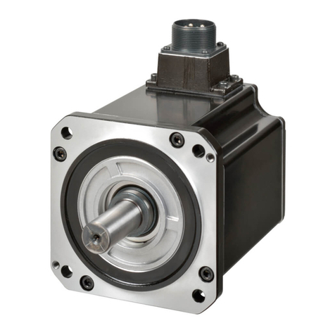
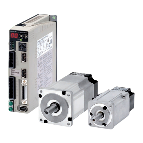
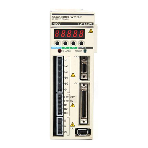
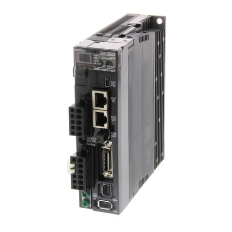
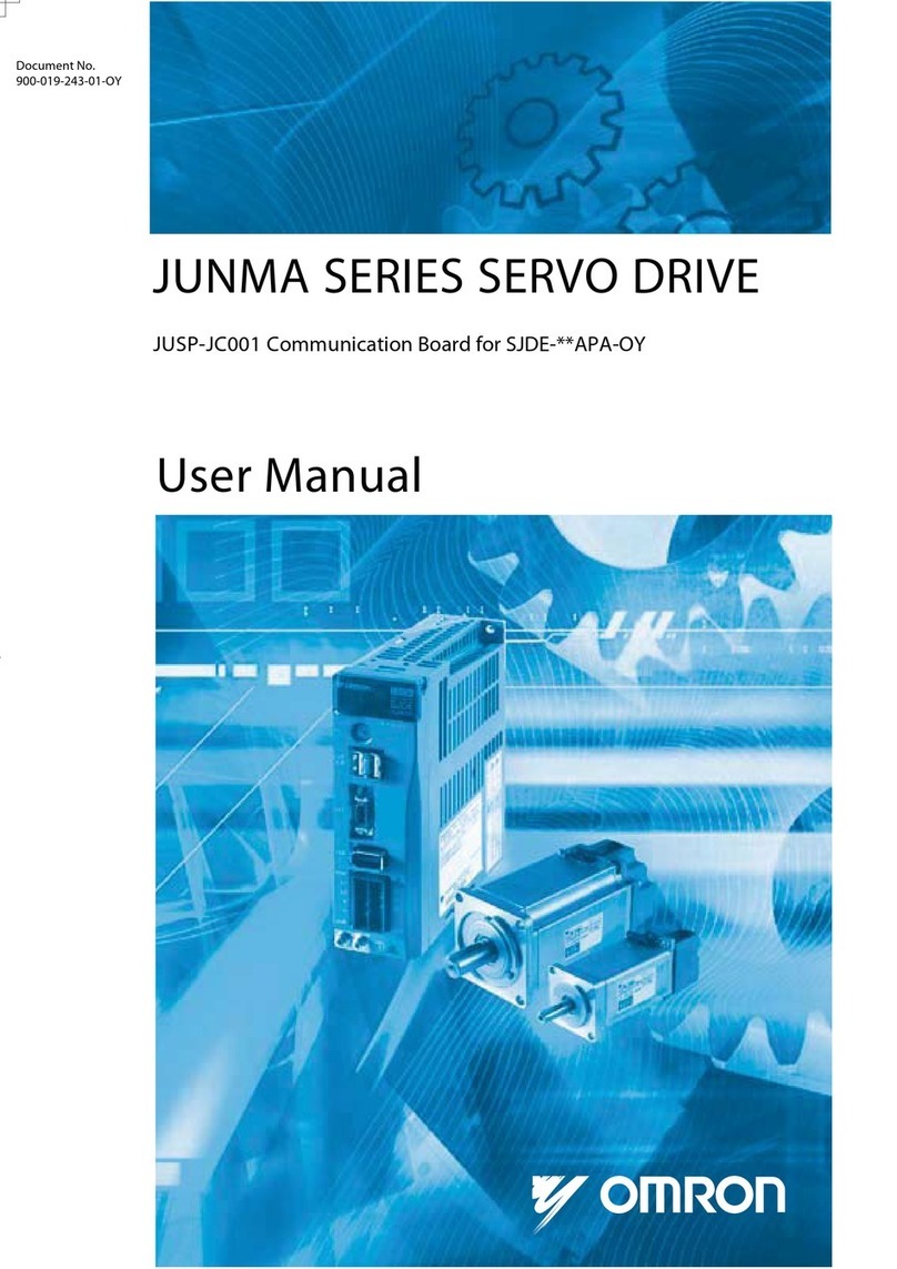
  9. Omron OMNUC G5 Series User manual

Omron OMNUC G5 Series User manual

Thank you for supporting OMRON and OMRON products. It was discovered that the following information is missing from the
OMNUC G5-series AC Servomotors/AC Servo Drives User's Manuals. We sincerely apologize for this oversight.
Please mark your manuals so that the corrections are noted on the pages concerned, and then securely add any required
pages from this Notification to the rear of the manual.
OMNUC G5-series AC Servomotors/AC Servo Drives
User's Manuals, Notification of Additional Information
To: All Customers August 2010
OMRON Corporation
Automation Systems HQ
■Applicable Manuals
1. Relevant location:
•
This Notification applies to the following manuals: OMNUC G5-series AC Servomotors/AC Servo Drives
User's Manual that was issued in June 2010 (Cat. No. I571-E1-02), OMNUC G5-series AC Servomotors/AC
Servo Drives with Built-in MECHATROLINK-II Communications User's Manual that was issued in November 2009
(Cat. No. I572-E1-01), and OMNUC G5-series AC Servomotors/AC Servo Drives with Built-in EtherCAT
Communications User's Manual that was issued in March 2010 (Cat. No. I573-E1-01).
Connection Example: Connection with a Safety Controller
Cat. No.
I571-E1-02
I572-E1-01
I573-E1-01
■Additional Information
2. Relevant location:
Cat. No.
I573-E1-01
■Correction
The safety function has been certified. Remove "(Application Pending)."
We recommend that you use the following wiring example to connect to a Safety Controller.
Connection with a Safety Controller (2 safety inputs and EDM output)
EDM output
SF1+
SF2+
SF2−
EDM+
EDM−
M
SF1−
Safety
Controller
Servo Drive
Safety input
0V
Test output
Safety input
EDM input
G9SP-series
Safety Controller
Safety output
(source)
Safety output 1
Safety output 2
10147
7-6
7-6
8-6
14, 19, 1-7, Chapter 8, 8-1
Page
Pages
Thank you for supporting OMRON and OMRON products.
Some mistakes were discovered in the manuals listed below. We sincerely apologize for these mistakes. Please mark your
manuals so that the corrections are noted on the pages concerned, and then securely add any required pages from this
Notification to the rear of the manual.
OMNUC G5-series AC Servomotors/AC Servo
Drives User's Manuals, Notification of Corrections
To: All Customers August 2010
OMRON Corporation
Automation Systems HQ
1. Relevant locations: Three Locations
•
This Notification applies to the following manuals: OMNUC G5-series AC Servomotors/AC Servo Drives
User's Manual that was issued in June 2010 (Cat. No. I571-E1-02), OMNUC G5-series AC Servomotors/
AC Servo Drives with Built-in MECHATROLINK-II Communications User's Manual that was issued in November 2009
(Cat. No. I572-E1-01), and OMNUC G5-series AC Servomotors/AC Servo Drives with Built-in EtherCAT
Communications User's Manual that was issued in March 2010 (Cat. No. I573-E1-01).
I571-E1-02
I572-E1-01
I573-E1-01
Safety I/O Signal Connections and External Signal Processing for Safety Connector Specifications
(CN8)
Safety Connector Specifications (CN8)
Connection of Safety I/O Signals and Processing of External Signals
SF1+
12 to 24 VDC
SF1−
4
3
1 kΩ
4 kΩ
SF2+
12 to 24 VDC
SF2−
6
8
EDM+
EDM−
FG
7
5
1 kΩ
10 Ω
Shell
Leakage current: 0.1 mA max.
Residual voltage: 1.7 V max.
■Correction
■Applicable Manual
Safety Connector Specifications (CN8)
Connection of Safety I/O Signals and Processing of External Signals Connection of Safety I/O Signals and Processing of External Signals
Maximum service voltage:
30 VDC or less
Maximum output current:
50 mADC
Cat. No.
<Corrected Contents><Current Contents>
4 kΩ
3-51
3-29
3-25 (Leakage current and residual voltage were added in only one location.)
SF1+
12 to
24 VDC
SF1−
4
3
1 kΩ
4.7 kΩ
SF2+
12 to
24 VDC
SF2−
6
8
EDM+
EDM−
FG
7
5
1 kΩ
10 Ω
Shell
Maximum service voltage: 30 VDC or less
Maximum output current: 50 mADC
4.7 kΩ
Page
Safety I/O Signal Connections and External Signal Processing for Safety Connector Specifications
(CN8)
2. Relevant location:
■Correction
EDM Output Circuit
External power supply
12 to 24 VDC
Maximum service voltage: 30 VDC or less
Maximum output current: 50 mA max.
7−EDM
8 +EDM
Di
Di: Surge voltage prevention diode
(Use a high-speed diode.)
10 Ω
Servo Drive
X
I571-E1-02
I572-E1-01
I573-E1-01
Cat. No.
EDM Output Circuit
<Corrected Contents><Current Contents>
External and Mounting Dimensions, 1,000-r/min Motors (200 V)
3. Relevant location:
I572-E1-01
Cat. No.
1,000-r/min Motors (200 V)
900 W (without Brake)
R88M-K90010H (-S2)
R88M-K90010T (-S2)
900 W (with Brake)
R88M-K90010H-B (S2)
R88M-K90010T-B (S2)
INC
ABS
INC
ABS
Encoder connector
Motor and brake
connector
LM
KB2
77.5
55
LL
116
60
130×130
45
41
55
M3, through
8h9
7
18
(Shaft end specifications with key and tap)
216
ø22h6
ø110h7
4-ø9
ø165
ø145
ø22h6
ø110h7
M5 (depth 12)
<Corrected Contents><Current Contents>
1,000-r/min Motors (200 V)
900 W (without Brake)
R88M-K90010H (-S2)
R88M-K90010T (-S2)
900 W (with Brake)
R88M-K90010H-B (S2)
R88M-K90010T-B (S2)
INC
ABS
INC
ABS
LM
KB2
77.5
70
LL
116
60
130×130
45
41 M3, through
8h9
7
18
(Shaft end specifications with key and tap)
216
ø22h6
ø110h7
4-ø9
ø165
ø145
ø22h6
ø110h7
■Correction
M5 (depth 12)
Leakage current: 0.1 mA max.
Residual voltage: 1.7 V max.
70
3-52
3-30
3-26
External power supply
12 to 24 VDC
Maximum service voltage: 30 VDC or less
Maximum output current: 50 mA max.
7−EDM
8 +EDM
Di
Di: Surge voltage prevention diode
(Use a high-speed diode.)
10 Ω
Servo Drive
X
2-43
Encoder connector
Motor and brake
connector
Page
Page
4. Relevant location:
■Correction
I572-E1-01
Cat. No.
<Corrected Contents><Current Contents>
External and Mounting Dimensions, 1,000-r/min Motors (400 V)
1,000-r/min Motors (400 V)
900 W (without Brake)
R88M-K90010F (-S2)
R88M-K90010C (-S2)
900 W (with Brake)
R88M-K90010F-B (S2)
R88M-K90010C-B (S2)
INC
ABS
INC
ABS
1,000-r/min Motors (400 V)
900 W (without Brake)
R88M-K90010F (-S2)
R88M-K90010C (-S2)
900 W (with Brake)
R88M-K90010F-B (S2)
R88M-K90010C-B (S2)
INC
ABS
INC
ABS
Encoder connector
Motor and brake
connector
LM
KB2
KB1
55
LL
60
130×130
45
41
55
M3, through
M5 (depth 12)
8h9
7
18
(Shaft end specifications with key and tap)
216
ø22h6
ø110h7
4-ø9
ø165
ø145
ø22h6
ø110h7
116 (without brake)
118 (with brake)
LM
KB2
KB1
LL
60
45
41
70
8h9
7
18
216
ø22h6
ø110h7
4-ø9
ø165
ø145
ø22h6
ø110h7
70
2-45
Encoder connector
Motor and brake
connector
130×130
M3, through
M5 (depth 12)
(Shaft end specifications with key and tap)
116 (without brake)
118 (with brake)
Page

Other manuals for OMNUC G5 Series

1

This manual suits for next models

3

Other Omron Servo Drive manuals

Omron R88D-UA User manual

Omron

Omron R88D-UA User manual

Omron sysmac 1S Series User guide

Omron

Omron sysmac 1S Series User guide

Omron OMNUC U R88M-U Series User manual

Omron

Omron OMNUC U R88M-U Series User manual

Omron R88M-K Series User manual

Omron

Omron R88M-K Series User manual

Omron SMARTSTEP A Series User manual

Omron

Omron SMARTSTEP A Series User manual

Omron R88M-1L Series User guide

Omron

Omron R88M-1L Series User guide

Omron OMNUC W Series User manual

Omron

Omron OMNUC W Series User manual

Omron R88D-KN ML2 Sries User manual

Omron

Omron R88D-KN ML2 Sries User manual

Omron R88D-KTA5L User manual

Omron

Omron R88D-KTA5L User manual

Omron R88M-W User manual

Omron

Omron R88M-W User manual

Omron G5 Series User manual

Omron

Omron G5 Series User manual

Omron 3G3RX Series User manual

Omron

Omron 3G3RX Series User manual

Omron OMNUC G Series User manual

Omron

Omron OMNUC G Series User manual

Omron R88L-EA-AF User manual

Omron

Omron R88L-EA-AF User manual

Omron OMNUC G5 Series User manual

Omron

Omron OMNUC G5 Series User manual

Omron CK M-CPU1 1 Series User guide

Omron

Omron CK M-CPU1 1 Series User guide

Omron R88M-W60010T User manual

Omron

Omron R88M-W60010T User manual

Omron OMNUC U Series User manual

Omron

Omron OMNUC U Series User manual

Omron SMARTSTEP R7M-A Series User manual

Omron

Omron SMARTSTEP R7M-A Series User manual

Omron SMARTSTEP 2 R88M-G Series User manual

Omron

Omron SMARTSTEP 2 R88M-G Series User manual

Omron 1S Series User manual

Omron

Omron 1S Series User manual

Omron R88M-U03030HA User manual

Omron

Omron R88M-U03030HA User manual

Omron CK5M-CPU 1 Series User guide

Omron

Omron CK5M-CPU 1 Series User guide

Omron R88M-K Series User manual

Omron

Omron R88M-K Series User manual

Popular Servo Drive manuals by other brands

Leadshine EL6-CAN user manual

Leadshine

Leadshine EL6-CAN user manual

Vescent Photonics D2-125 manual

Vescent Photonics

Vescent Photonics D2-125 manual

GFA ELEKTROMATEN SI 75.15-55,00 installation instructions

GFA ELEKTROMATEN

GFA ELEKTROMATEN SI 75.15-55,00 installation instructions

Parker Gemini GV Series installation guide

Parker

Parker Gemini GV Series installation guide

Bosch Rexroth MS2S operating manual

Bosch

Bosch Rexroth MS2S operating manual

Allen-Bradley Kinetix 5500 user manual

Allen-Bradley

Allen-Bradley Kinetix 5500 user manual

SEW-Eurodrive CMP40 - 112 operating instructions

SEW-Eurodrive

SEW-Eurodrive CMP40 - 112 operating instructions

INVT MH860A Series Operation manual

INVT

INVT MH860A Series Operation manual

Inovance IS620P Series user manual

Inovance

Inovance IS620P Series user manual

YASKAWA E-V Series user manual

YASKAWA

YASKAWA E-V Series user manual

Fuji Electric Alpha 5 Installation and Wiring

Fuji Electric

Fuji Electric Alpha 5 Installation and Wiring

Rockwell Automation Allen-Bradley Kinetix 5100 Migration guide

Rockwell Automation

Rockwell Automation Allen-Bradley Kinetix 5100 Migration guide

Sumitomo Cyclo BBB4 quick start guide

Sumitomo

Sumitomo Cyclo BBB4 quick start guide

ZLTECH ZLAC8015 manual

ZLTECH

ZLTECH ZLAC8015 manual

Emerson TRINORM 436 Series instruction manual

Emerson

Emerson TRINORM 436 Series instruction manual

Kollmorgen Seidel 6SM56 Series Technical description

Kollmorgen Seidel

Kollmorgen Seidel 6SM56 Series Technical description

Danfoss 176F6617 installation instructions

Danfoss

Danfoss 176F6617 installation instructions

Leadshine Technology DB810A user manual

Leadshine Technology

Leadshine Technology DB810A user manual

manuals.online logo
manuals.online logoBrands
  • About & Mission
  • Contact us
  • Privacy Policy
  • Terms and Conditions

Copyright 2025 Manuals.Online. All Rights Reserved.