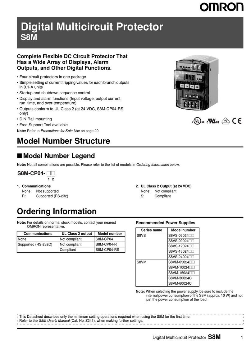
Omron S8M User manual

At the end of this document you will find links to products related to this catalog. You can go directly to our shop by
clicking HERE. HERE

USER'S MANUAL Cat. No. Z241-E1-01
Digital Multicircuit Protector S8M
S8M
Digital Multicircuit
Protector
USER'S MANUAL
Cat. No. Z241-E1-01

S8M Digital Multicircuit Protector
User’s Manual
Produced June 2006

iv

v
TABLE OF CONTENTS
SECTION 1
Features and Functions . . . . . . . . . . . . . . . . . . . . . . . . . . . . . 1
1-1 Overview of Features and Functions . . . . . . . . . . . . . . . . . . . . . . . . . . . . . . . . . . . . . . . . . . . 2
1-2 S8M Operations and Operating Modes . . . . . . . . . . . . . . . . . . . . . . . . . . . . . . . . . . . . . . . . . 7
1-3 Table of Basic Functions . . . . . . . . . . . . . . . . . . . . . . . . . . . . . . . . . . . . . . . . . . . . . . . . . . . . 10
1-4 S8M Operating Procedure . . . . . . . . . . . . . . . . . . . . . . . . . . . . . . . . . . . . . . . . . . . . . . . . . . . 11
SECTION 2
Specifications and Functions . . . . . . . . . . . . . . . . . . . . . . . . . 13
2-1 Component Names and Functions. . . . . . . . . . . . . . . . . . . . . . . . . . . . . . . . . . . . . . . . . . . . . 14
2-2 Internal Configuration . . . . . . . . . . . . . . . . . . . . . . . . . . . . . . . . . . . . . . . . . . . . . . . . . . . . . . 16
2-3 Specifications. . . . . . . . . . . . . . . . . . . . . . . . . . . . . . . . . . . . . . . . . . . . . . . . . . . . . . . . . . . . . 18
2-4 Basic Function Details. . . . . . . . . . . . . . . . . . . . . . . . . . . . . . . . . . . . . . . . . . . . . . . . . . . . . . 22
2-5 Startup Sequence Function . . . . . . . . . . . . . . . . . . . . . . . . . . . . . . . . . . . . . . . . . . . . . . . . . .30
2-6 Shutdown Sequence Function . . . . . . . . . . . . . . . . . . . . . . . . . . . . . . . . . . . . . . . . . . . . . . . . 31
SECTION 3
Installation and Wiring . . . . . . . . . . . . . . . . . . . . . . . . . . . . . 33
3-1 Installation Environment . . . . . . . . . . . . . . . . . . . . . . . . . . . . . . . . . . . . . . . . . . . . . . . . . . . . 34
3-2 Installation . . . . . . . . . . . . . . . . . . . . . . . . . . . . . . . . . . . . . . . . . . . . . . . . . . . . . . . . . . . . . . . 35
3-3 Wiring . . . . . . . . . . . . . . . . . . . . . . . . . . . . . . . . . . . . . . . . . . . . . . . . . . . . . . . . . . . . . . . . . . 39
3-4 RS-232C Port Wiring (S8M-CP04-R and S8M-CP04-RS Only) . . . . . . . . . . . . . . . . . . . . . 43
SECTION 4
Parameter Settings . . . . . . . . . . . . . . . . . . . . . . . . . . . . . . . . . 47
4-1 Parameter Table . . . . . . . . . . . . . . . . . . . . . . . . . . . . . . . . . . . . . . . . . . . . . . . . . . . . . . . . . . . 48
4-2 Parameter Setting Ranges . . . . . . . . . . . . . . . . . . . . . . . . . . . . . . . . . . . . . . . . . . . . . . . . . . .49
4-3 Switching the Operating Mode . . . . . . . . . . . . . . . . . . . . . . . . . . . . . . . . . . . . . . . . . . . . . . . 49
4-4 Changing the Protection Level . . . . . . . . . . . . . . . . . . . . . . . . . . . . . . . . . . . . . . . . . . . . . . . 54
4-5 Switching to Setting Mode . . . . . . . . . . . . . . . . . . . . . . . . . . . . . . . . . . . . . . . . . . . . . . . . . .55
4-6 Individual Branch Output Settings . . . . . . . . . . . . . . . . . . . . . . . . . . . . . . . . . . . . . . . . . . . . 56
4-7 Shared Parameter Settings . . . . . . . . . . . . . . . . . . . . . . . . . . . . . . . . . . . . . . . . . . . . . . . . . . .60
4-8 Special Settings and Communications Settings. . . . . . . . . . . . . . . . . . . . . . . . . . . . . . . . . . . 64
SECTION 5
Trial Operation to Actual Operation . . . . . . . . . . . . . . . . . . 73
5-1 Test Mode . . . . . . . . . . . . . . . . . . . . . . . . . . . . . . . . . . . . . . . . . . . . . . . . . . . . . . . . . . . . . . . 74
5-2 Connection/Disconnection Test . . . . . . . . . . . . . . . . . . . . . . . . . . . . . . . . . . . . . . . . . . . . . . . 76
5-3 Checking Sequence Operation. . . . . . . . . . . . . . . . . . . . . . . . . . . . . . . . . . . . . . . . . . . . . . . . 77
5-4 Run Mode . . . . . . . . . . . . . . . . . . . . . . . . . . . . . . . . . . . . . . . . . . . . . . . . . . . . . . . . . . . . . . . 78

vi
TABLE OF CONTENTS
SECTION 6
Support Tool . . . . . . . . . . . . . . . . . . . . . . . . . . . . . . . . . . . . . . 81
6-1 Installing the Support Tool . . . . . . . . . . . . . . . . . . . . . . . . . . . . . . . . . . . . . . . . . . . . . . . . . . 82
6-2 Starting the Support Tool. . . . . . . . . . . . . . . . . . . . . . . . . . . . . . . . . . . . . . . . . . . . . . . . . . . . 85
6-3 Setting and Saving Parameters . . . . . . . . . . . . . . . . . . . . . . . . . . . . . . . . . . . . . . . . . . . . . . . 87
6-4 Monitoring . . . . . . . . . . . . . . . . . . . . . . . . . . . . . . . . . . . . . . . . . . . . . . . . . . . . . . . . . . . . . . . 92
6-5 Other Settings . . . . . . . . . . . . . . . . . . . . . . . . . . . . . . . . . . . . . . . . . . . . . . . . . . . . . . . . . . . . 96
SECTION 7
Communications . . . . . . . . . . . . . . . . . . . . . . . . . . . . . . . . . . . 99
7-1 CompoWay/F Communications Specifications. . . . . . . . . . . . . . . . . . . . . . . . . . . . . . . . . . . 100
7-2 Frame Structure . . . . . . . . . . . . . . . . . . . . . . . . . . . . . . . . . . . . . . . . . . . . . . . . . . . . . . . . . . . 101
7-3 Details of Services . . . . . . . . . . . . . . . . . . . . . . . . . . . . . . . . . . . . . . . . . . . . . . . . . . . . . . . . . 109
7-4 Read Controller Information . . . . . . . . . . . . . . . . . . . . . . . . . . . . . . . . . . . . . . . . . . . . . . . . .112
7-5 Read Controller Attributes. . . . . . . . . . . . . . . . . . . . . . . . . . . . . . . . . . . . . . . . . . . . . . . . . . . 114
7-6 Read Controller Status. . . . . . . . . . . . . . . . . . . . . . . . . . . . . . . . . . . . . . . . . . . . . . . . . . . . . . 115
7-7 Echoback Test . . . . . . . . . . . . . . . . . . . . . . . . . . . . . . . . . . . . . . . . . . . . . . . . . . . . . . . . . . . . 116
7-8 Operation Command . . . . . . . . . . . . . . . . . . . . . . . . . . . . . . . . . . . . . . . . . . . . . . . . . . . . . . . 117
7-9 Response Code List . . . . . . . . . . . . . . . . . . . . . . . . . . . . . . . . . . . . . . . . . . . . . . . . . . . . . . . . 118
7-10 ASCII List . . . . . . . . . . . . . . . . . . . . . . . . . . . . . . . . . . . . . . . . . . . . . . . . . . . . . . . . . . . . . . . 119
SECTION 8
Error Processing . . . . . . . . . . . . . . . . . . . . . . . . . . . . . . . . . . . 121
8-1 Troubleshooting. . . . . . . . . . . . . . . . . . . . . . . . . . . . . . . . . . . . . . . . . . . . . . . . . . . . . . . . . . . 122
8-2 Seven-segment Error Codes. . . . . . . . . . . . . . . . . . . . . . . . . . . . . . . . . . . . . . . . . . . . . . . . . . 123
8-3 Clearing Errors. . . . . . . . . . . . . . . . . . . . . . . . . . . . . . . . . . . . . . . . . . . . . . . . . . . . . . . . . . . . 125
Appendices
A Glossary . . . . . . . . . . . . . . . . . . . . . . . . . . . . . . . . . . . . . . . . . . . . . . . . . . . . . . . . . . . . . . . . 129
B List of Operations . . . . . . . . . . . . . . . . . . . . . . . . . . . . . . . . . . . . . . . . . . . . . . . . . . . . . . . . . 133
Revision History . . . . . . . . . . . . . . . . . . . . . . . . . . . . . . . . . . . 137

vii
About this Manual:
This manual describes the installation and operation of the S8M Digital Multicircuit Protector and
includes the sections described below.
Please read this manual carefully and be sure you understand the information provided before
attempting to install or operate the S8M Digital Multicircuit Protector. Be sure to read the precautions
provided in the following section.
Precautions provides general precautions for using the S8M Digital Multicircuit Protector and related
devices.
Section 1 introduces the features and functions of the S8M Digital Multicircuit Protector and concepts
related to its operation.
Section 2 identifies the S8M Digital Multicircuit Protector’s components, provides specifications, and
describes the basic functions.
Section 3 describes how to install and wire the S8M Digital Multicircuit Protector.
Section 4 describes how to set the S8M’s various parameters.
Section 5 describes how to connect the branch outputs and test operation.
Section 6 describes how to install and operate the S8M Support Tool.
Section 7 describes how to use S8M communications.
Section 8 provides information on troubleshooting problems that may occur with the S8M Digital Multi-
circuit Protector.
The appendices provide a glossary of terms related to the S8M and flowcharts of S8M key operations.
!WARNING Failure to read and understand the information provided in this manual may result in per-
sonal injury or death, damage to the Product, or Product failure. Please read each section
in its entirety and be sure you understand the information provided in the section and
related sections before attempting any of the procedures or operations given.

viii

ix
Read and Understand this Manual
Please read and understand this manual before using the product. Please consult your OMRON
representative if you have any questions or comments.
Warranty and Limitations of Liability
WARRANTY
OMRON's exclusive warranty is that the products are free from defects in materials and workmanship for a
period of one year (or other period if specified) from date of sale by OMRON.
OMRON MAKES NO WARRANTY OR REPRESENTATION, EXPRESS OR IMPLIED, REGARDING NON-
INFRINGEMENT, MERCHANTABILITY, OR FITNESS FOR PARTICULAR PURPOSE OF THE PRODUCTS. ANY
BUYER OR USER ACKNOWLEDGES THAT THE BUYER OR USER ALONE HAS DETERMINED THAT THE
PRODUCTS WILL SUITABLY MEET THE REQUIREMENTS OF THEIR INTENDED USE. OMRON DISCLAIMS ALL
OTHER WARRANTIES, EXPRESS OR IMPLIED.
LIMITATIONS OF LIABILITY
OMRON SHALL NOT BE RESPONSIBLE FOR SPECIAL, INDIRECT, OR CONSEQUENTIAL DAMAGES,
LOSS OF PROFITS OR COMMERCIAL LOSS IN ANY WAY CONNECTED WITH THE PRODUCTS,
WHETHER SUCH CLAIM IS BASED ON CONTRACT, WARRANTY, NEGLIGENCE, OR STRICT
LIABILITY.
In no event shall the responsibility of OMRON for any act exceed the individual price of the product on which
liability is asserted.
IN NO EVENT SHALL OMRON BE RESPONSIBLE FOR WARRANTY, REPAIR, OR OTHER CLAIMS
REGARDING THE PRODUCTS UNLESS OMRON'S ANALYSIS CONFIRMS THAT THE PRODUCTS
WERE PROPERLY HANDLED, STORED, INSTALLED, AND MAINTAINED AND NOT SUBJECT TO
CONTAMINATION, ABUSE, MISUSE, OR INAPPROPRIATE MODIFICATION OR REPAIR.
Application Considerations
SUITABILITY FOR USE
OMRON shall not be responsible for conformity with any standards, codes, or regulations that apply to the
combination of products in the customer's application or use of the products.
At the customer's request, OMRON will provide applicable third party certification documents identifying
ratings and limitations of use that apply to the products. This information by itself is not sufficient for a
complete determination of the suitability of the products in combination with the end product, machine,
system, or other application or use.
The following are some examples of applications for which particular attention must be given. This is not
intended to be an exhaustive list of all possible uses of the products, nor is it intended to imply that the uses
listed may be suitable for the products:
•Outdoor use, uses involving potential chemical contamination or electrical interference, or conditions or
uses not described in this manual.
•Nuclear energy control systems, combustion systems, railroad systems, aviation systems, medical
equipment, amusement machines, vehicles, safety equipment, and installations subject to separate
industry or government regulations.
•Systems, machines, and equipment that could present a risk to life or property.
Please know and observe all prohibitions of use applicable to the products.
NEVER USE THE PRODUCTS FOR AN APPLICATION INVOLVING SERIOUS RISK TO LIFE OR
PROPERTY WITHOUT ENSURING THAT THE SYSTEM AS A WHOLE HAS BEEN DESIGNED TO
ADDRESS THE RISKS, AND THAT THE OMRON PRODUCTS ARE PROPERLY RATED AND INSTALLED
FOR THE INTENDED USE WITHIN THE OVERALL EQUIPMENT OR SYSTEM.
PROGRAMMABLE PRODUCTS
OMRON shall not be responsible for the user's programming of a programmable product, or any
consequence thereof.

x
Disclaimers
CHANGE IN SPECIFICATIONS
Product specifications and accessories may be changed at any time based on improvements and other
reasons.
It is our practice to change model numbers when published ratings or features are changed, or when
significant construction changes are made. However, some specifications of the products may be changed
without any notice. When in doubt, special model numbers may be assigned to fix or establish key
specifications for your application on your request. Please consult with your OMRON representative at any
time to confirm actual specifications of purchased products.
DIMENSIONS AND WEIGHTS
Dimensions and weights are nominal and are not to be used for manufacturing purposes, even when
tolerances are shown.
PERFORMANCE DATA
Performance data given in this manual is provided as a guide for the user in determining suitability and does
not constitute a warranty. It may represent the result of OMRON's test conditions, and the users must
correlate it to actual application requirements. Actual performance is subject to the OMRON Warranty and
Limitations of Liability.
ERRORS AND OMISSIONS
The information in this document has been carefully checked and is believed to be accurate; however, no
responsibility is assumed for clerical, typographical, or proofreading errors, or omissions.

xi
■Precaution Classifications
The following conventions are used to indicate and classify precautions in this
manual.
Always heed the information provided with them. Failure to heed precautions
can result in injury to people or damage to property.
■Cautions
Safety Precautions
CAUTION
Indicates a potentially hazardous situation which, if not
avoided, may result in minor or moderate injury or in
property damage.
CAUTION
Minor electric shock, fire, or Product failure may occasionally
occur. Do not disassemble, modify, or repair the Product or touch
interior of the Product.
Minor burns may occasionally occur. Do not touch the Product
during power is being supplied or immediately after power is
turned OFF.
Fire may occasionally occur. Tighten terminal screws to the
specified torque.
Power input terminals: M4 1.08 N·m (9.6 in. lb.)
Branch output terminals: M3.5 0.8 to 1.0 N·m (7.2 to 8.8 in. lb.)
Minor electric shock, fire, or Product failure may occasionally
occur. Do not allow any pieces of metal or conductors or any
clippings or cuttings resulting from installation work to enter the
Product.
The Product will be damaged. Do not incorrectly connect the
polarity of power input terminals.

xii
■Operating the S8M
Unlike ordinary mechanical circuit protectors, the S8M does not have contacts for switching. The S8M uses
semiconductor relays to switch the circuits ON/OFF and cut off the outputs. Read and understand the following
features before operating the S8M.
■Installation and Storage Environment
1. Store the Product at an ambient temperature of –25 to 65°C and relative humidity of 25% to 90%.
2. Poor heat dissipation resulting from improper installation conditions may occasionally deteriorate or
damage internal parts. Do not use any mounting method other than a standard one.
3. Internal parts may occasionally be deteriorated or broken. Do not use the Product in conditions exceeding
the derating (in portion (1) of the derating curve).
4. The surrounding air temperature for UL 508 listing and UL 60950-1 recognition is 50°C.
5. Use the Product where the relative humidity is 25% to 85%.
6. Do not use the Product where it would be subjected to direct sunlight.
7. Do not use the Product where it would be subjected to the possibility of penetration of liquid, foreign
substance, or corrosive gas.
8. Do not use the Product where it would be subjected to shock or vibration. A device such as a contact
breaker may be a vibration source. Install the Product as far as possible from external devices.
Additionally, install a PFP-M End Plate on each side of the Product.
9. If the Product is used in an area with excessive electronic noise, be sure to separate the Product as far as
possible from the noise sources.
10. Tripping performance depends on the ambient operating temperature. Use the Product within the derating
curve (page xiii).
■Wiring
•Minor electric shock during operation may occasionally occur. Always attach the terminal cover when
using the S8M.
•Minor fire may possibly occur. Ensure that input and output terminals are wired correctly.
•Increases in the temperature of internal parts resulting from heating of wiring materials may result in
deterioration or damage to internal parts. Use wiring materials suitable to the current being used. The
following wiring materials, torque, and strip length are recommended to prevent heating and possible fires
in wiring materials.
Recommended Wire Types
•It is conceivable that internal parts may be deteriorated or damaged. Do not repeatedly perform tripping or
recovery operations more than necessary.
•Do not apply more than 100 N force to the terminal block when tightening screws.
•Be sure to remove the sheet covering the Product for machining before power-ON so that it does not
interfere with heat dissipation.
•The S8M takes a DC power input. Do not connect AC power to the power input terminals.
Precautions for Safe Use
Terminals Wiring materials Torque Strip length
Power input terminals AWG14 (2.081 mm2) ×2 Solid,
Stranded
1.08 N·m (9.6 in. lb.) 8 to 10 mm
Branch output terminals AWG16 to 20
(1.309 to 0.517 mm2)
0.8 to 1.0 N·m (7.2 to 8.8 in. lb.) 6 to 7 mm
Other terminals AWG18 to 26
(0.823 to 0.129 mm2)
--- 10 mm

xiii
■Derating Curve
The temperature range within which the S8M can be used is restricted by the maximum current that normally
flows for any one branch output. This restriction is given as a derating curve.
Use the S8M within the derating curve. If necessary, use forced cooling.
−20
100
80
60
40
20
0
20
60
50
40
30
10
0
−10
S8M-CP04 or S8M-CP04-R: Maximum output current of 4.0 A
S8M-CP04-RS: Maximum output current of 3.8 A
(1)
Ambient operating temperature (°C)
Maximum applied current for any one branch output (%)

xiv
■Installation
•Mounting Direction
Always install the S8M on a DIN Rail. For details, refer to 3-2 Installation.
•Mounting Space
The long-term reliability of the S8M can be increased by installing it properly and sufficiently considering
heat dissipation. Install the S8M so that the air flow circulates around it, because the S8M is designed to
radiate heat by means of natural air circulation.
Although two or more S8M Multicircuit Protectors can be installed side by side, they must be separated
from sources of heat, such as the switching power supply installed to the input side, by the distances
given in 3-1 Installation Environment.
■Input Voltage
Input voltage range: 19.2 to 26.4 VDC
•The S8M provides abnormal voltage protection. All branch outputs will be cut off if the input voltage exceeds
28.8 VDC. This function, however, does not protect loads and internal parts from high voltages in all cases.
Be sure the input voltage is within the rated range.
•Outputs may be cut off by the abnormal voltage protection with loads that generate reverse peak electro-
motive force.
•A voltage drop occurs within the S8M. Be sure to consider the effect of the voltage drop on the output
voltage.
■Input Power Supply Selection
•When selecting a power supply, be sure to add the S8M’s internal power consumption (about 10 W) to the
power consumption of the loads.
•The overcurrent protection characteristics of the power supply connected to the input side can cause a
voltage drop, possibly resulting in a cutoff.
•If the capacity of the input power supply is too small compared with the load, the overcurrent protection
characteristics of the power supply can prevent the S8M from starting or can cause a voltage drop, possibly
resulting in a cutoff.
•If secondary voltage of the power supply rises or falls too slowly, the overcurrent protection characteristics of
the power supply can prevent the S8M from starting or can cause a voltage drop, possibly resulting in a
cutoff.
■Tripping Performance
There are two tripping types that can be used to detect output current characteristics: Standard detection
(overcurrents lasting 80 ms are cutoff within 100 ms) and Instantaneous detection (overcurrents lasting 20 ms
are cutoff within 10 ms). Set the best tripping output current characteristics.
•If the S8M is tripped, always remove the cause first and then reset the S8M.
•If using a load with a fixed power operation, a cutoff may occur when the power supply is turned OFF.
•The accuracy of the tripping current is ±0.3 A.
Precautions for Correct Use
Standard horizontal mounting OK
Upward-facing mounting Incorrect
Other mounting directions Incorrect

xv
■Startup Delay
To prevent cutoffs caused by large surge currents when the equipment starts, the S8M has a startup delay that
disables the tripping operation for 70 ms after the semiconductor relay turns ON.
•The startup delay will not operate when a relay or other device is used for ON/OFF control on the output side
of the S8M, so a tripping operation may occasionally occur.
■Withstand Voltage Test
The S8M is designed to withstand 500 VAC for 1 minute between the power input terminals and all branch
output terminals, between all signal output terminals and all external tripping input terminals, between all
signal output terminals and all communications terminals, and between all external tripping input terminals and
all communications terminals.
Note •The S8M may possibly be damaged from the impulse voltage if a testing device switch is used to
abruptly apply or shut off 500 VAC. Increase the applied voltage gradually using the voltage
adjustment on the testing device.
•Always short the specified terminals so that the voltage is applied to all of the terminals at the same
time.
•The power input terminals and branch output terminals are not isolated. Do not perform dielectric
strength tests between the input and output terminals.
■Voltage Display
The voltage detection function monitors the voltage at the power input terminals. Measure the voltage at the
branch outputs to confirm that the output voltage is correct.
■Series Connections
An S8M cannot be connected in series to another S8M’s output and branch outputs cannot be connected in
series.
•Do not connect S8Ms in series.
•Do not connect S8M branch outputs in series.
AC/DC
power supply
+
−
+
−
S8M S8M
Incorrect
Incorrect
+
−
+
−
+
−
+
−
S8M
S8M
S8M
+
+
−
−
AC/DC
power supply
AC/DC
power supply
Incorrect

xvi
■Parallel Connections
An S8M cannot be connected in parallel with another S8M’s output and branch outputs cannot be connected
in parallel.
•Do not connect branch outputs in parallel.
■Backup Device Connections
Observe the following precautions when using a backup device, such as one from OMRON's S8T Series.
•If a backup device is connected to an S8M branch output, the backup current will be supplied to other
branches through internal circuits and internal parts may also be deteriorated or damaged. When using a
backup device with the S8M, connect the backup device to the power input side.
•When connecting a backup device to the S8M input side, the backup time will be shorter than normal due to
internal power consumption. Always confirm the backup time when using a backup device.
■Terminal Block Plating
The tripping alarm output, alarm output, over-temperature output, and external tripping input terminals, as well
as the connecting sections of the communications terminals, are gold-plated. If connection failures occur, we
recommend making connections with the wires made from the same material.
+
−
S8M
S8M
+
+
−
−
AC/DC
power supply
Incorrect
Incorrect
+
−
+
−
+
−
S8M
AC/DC
power supply

xvii
■Notation in this Manual
There are three models of S8M Digital Multicircuit Protectors covered in this manual: the S8M-CP04 (model
without an RS-232C port), S8M-CP04-R, and S8M-CP04-RS (UL Class 2 output model). These are collec-
tively referred to as the S8M. The functions and specifications described in this manual are shared by all three
models, unless differences are mentioned specifically.
■Notation of Setting Data
Setting data codes and contents are displayed in seven-segment display characters, as shown in the following
diagram.
Using this Manual
V

xviii

1
SECTION 1
Features and Functions
This section describes the features and functions of the S8M.
1-1 Overview of Features and Functions. . . . . . . . . . . . . . . . . . . . . . . . . . . . . . . . 2
1-2 S8M Operations and Operating Modes. . . . . . . . . . . . . . . . . . . . . . . . . . . . . . 7
1-3 Table of Basic Functions. . . . . . . . . . . . . . . . . . . . . . . . . . . . . . . . . . . . . . . . . 10
1-4 S8M Operating Procedure. . . . . . . . . . . . . . . . . . . . . . . . . . . . . . . . . . . . . . . . 11

2
Overview of Features and Functions Section 1-1
1-1 Overview of Features and Functions
The S8M Digital Multicircuit Protector incorporates four circuit protectors in
one package. The four 24-VDC, semiconductor relay circuit protectors can be
set digitally.
Unlike mechanical circuit protectors, the S8M is equipped with the following
functions that use digital processing and provide a variety of advantages.
Connection and Tripping
Operations Using
Semiconductor Relays
The four branch outputs are independent of each other and are connected/cut
off by semiconductor relays. In comparison to traditional mechanical circuit
protectors, the semiconductor relays are not consumable parts, so they have
a long lifetime.
Tripping Output Current
Can Be Set in 0.1-A Units
The S8M is a digital device, so each branch output's tripping current can be
set freely between 0.5 and 4.0 A (0.5 to 3.8 A for the S8M-CP04-RS). The
abnormal current tripping value and overcurrent alarm value can be set as the
circuit protector's rated currents. In addition, the tripping type can be set to
standard detection (tripping within 100 ms) or instantaneous detection (trip-
ping within 20 ms).
Voltage, Temperature, and
Run Time Can Also Be
Monitored
The S8M monitors the input voltage, internal temperature, and run time, along
with the input current. The input current, input voltage, and internal tempera-
ture measurements are continuously converted from analog to digital and
these values, as well as the run time, are compared to preset parameters. If a
value exceeds the corresponding set value, the output will be cut off or an
alarm will be output and the error will be indicated on the seven-segment dis-
play. These functions increase the device's added value, while also providing
important maintenance information.
Monitoring Operation with
the Seven-segment
Display
The S8M continuously converts the input voltage, current, and internal tem-
perature from analog to digital. These values, as well as the run time, can be
checked easily on the S8M's seven-segment display.
Typical mechanical circuit protectors
Normal contact-style
circuit protector
S8M Digital Multicircuit
Protector
Overcurrent
tripping device
Overcurrent
detection circuit
Other manuals for S8M
1
Table of contents
Other Omron Surge Protector manuals