manuals.online logo
Brands
  1. Home
  2. •
  3. Brands
  4. •
  5. Chenzhu
  6. •
  7. Surge Protector
  8. •
  9. Chenzhu GS8567-EX User manual

Chenzhu GS8567-EX User manual

GS8567-EX
GYB16.1339
IECEx CQM11.0003
DNV11 ATEX 08693X
CZ.GS8567-EX.11(S)E-5.3/16.03
5
4
1
2
3
3
2
1
XK06-014-00557
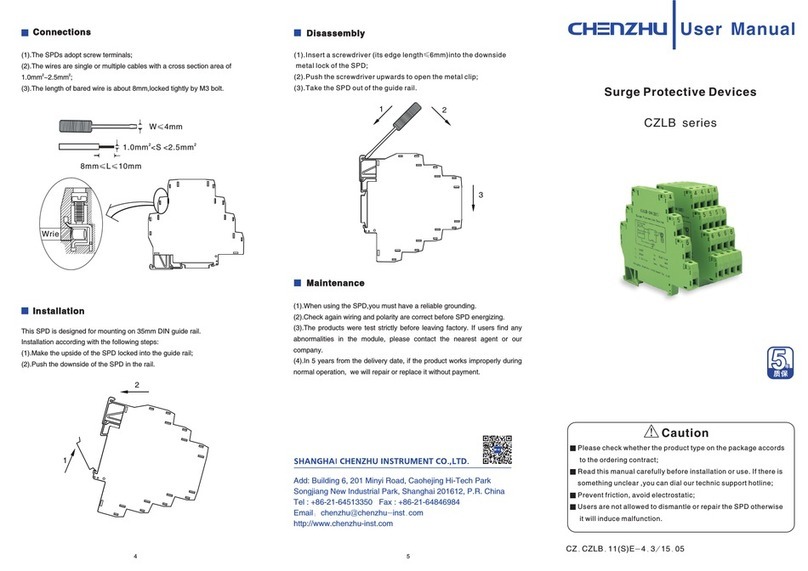
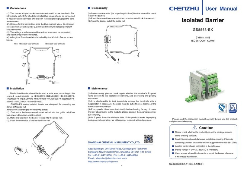
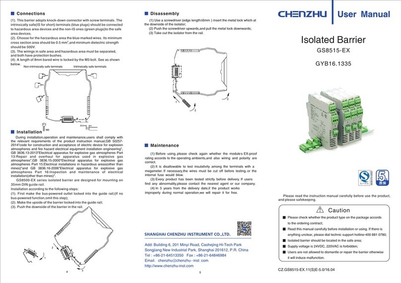
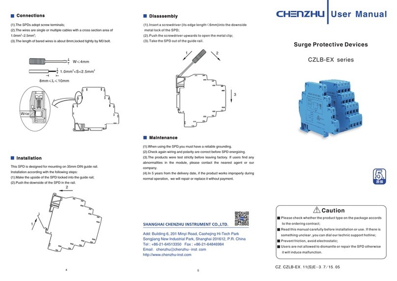
Connections
(1)
(2).
(3).
(4).
. This barrier adopts knock-down connector with screw terminals. The
intrinsically safe(IS for short) terminals (blue plugs) should be connected
to hazardous area devices and the non-IS ones (green plugs)to the safe
area devices.
Choose for the harzardous area the blue-marked wires. Its minimum
2
cross section area should be 0.5 mm ,and minimum dielectric strength
should be 500V.
The wirings in safe area and hazardous area must be separated,
and both have protection bushes.
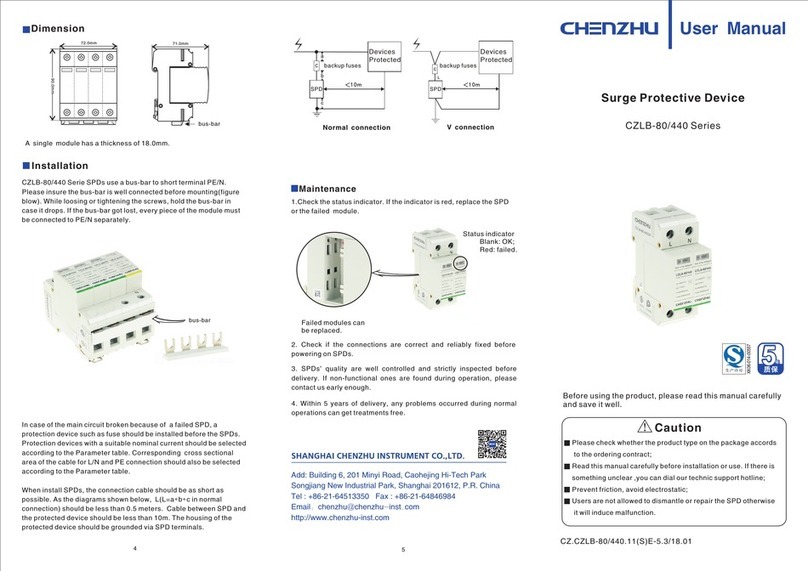
A length of 8mm bared wire is locked by the M3 bolt. See as shown
below.
Installation
The isolated barrier should be located at safe area, according to
the related requirements in IEC60079-17(EN60079-17)and
IEC60079-19(EN60079-19).
GS8500-EX series isolated barrier are designed for mounting on
35mm DIN guide rail.
Installation according to the following steps:
(1). First make the bus-powered outlet locked into the guide rail;(If no
bus-powered function,omit this step);
(2). Make the upside of the barrier locked into the guide rail;
(3). Push the downside of the barrier in the rail.
Disassembly
(1).Insert a screwdriver (its edge length≤6mm)into the downside metal
lock of the barrier;
(2).Push the screwdriver upwards,then prize the metal lock downwards;
(3).Take the barrier out of the guide rail.
(1).Before using, please check again whether the module’s Ex-proof
rating accords to the operation conditions, and also wiring and polarity
are correct.
(2).It is disallowable to test insulativity among the terminals with a
megameter. If necessary, the wires must be cut off before testing ,or the
internal fuse would blow.
(3).Every product has been test strictly before leaving factory. If users
find any abnormality in the module, please contact the nearest agent or
our company.
(4).In 5 yeras from the delivery date, if the product works improperly
during normal operation, we will repair or replace it without payment.
Non-intrinsically safe terminals Intrinsically safe terminals
Maintenance
Add: Building 6, 201 Minyi Road, Caohejing Hi-Tech Park
Songjiang New Industrial Park, Shanghai 201612, P.R. China
Tel : +86-21-64513350 Fax : +86-21-64846984
Email:chenzhu@chenzhu-inst.com
http://www.chenzhu-inst.com
Isolated Barrier
User Manual
Caution
Please check whether the product type on the package accords
to the ordering contract;
Read this manual carefully before installation or using. If there is
something unclear, please dial technic support hotline-400 881 0780;
Isolated barrier should be located in the safe area;
Supply voltage is 24VDC, 220VAC is forbidden;
Users are not allowed to dismantle or repair the barrier otherwise
it will induce malfunction.
Please read the instruction manual carefully before use the product,
and please safekeeping.
M3
8.0
Number of channels: 1
Supply voltage: 20~35V DC
Current consumption:
≤55mA(at 24Vdc supply,20mA output)
Safe-area input:
Current: 0/4~20mA, HART digital signal
Voltage drop: ≤6V
Hazardous-area output:
Current: 0/4~20mA, HART digital signal
Load resistance: RL800Ω
Load resistance: RL≥250Ω(HART)
Transfer accuracy: 0.1%F.S.
Temperature drift: 0.005%F.S./℃
Response time: Reach 90% of final value in 2ms
Power supply protection: Protect the barrier form reverse supply voltage
destroy
Load short-circuit alarm: When output load≤80Ω, go into short circuit
alarm state, and output is zero.
Electromagnetic compatibility: According to IEC 61326-1(GB/T 18268),
IEC 61326-3-1
Dielectric strength:
Between non-intrinsically safe part and intrinsically safe part≥2500VAC
Between power supply part and non-intrinsically safe part≥500VAC
Insulation resistance:
Between non-intrinsically safe part and intrinsically safe part≥100MΩ
Between power supply part and non-intrinsically safe part≥100MΩ
Weight: Approx.100g
Suitable location: Mounting in non-hazardous area, and connected to
the IS apparatus in zone 0 hazardous area.
Suitable IS apparatus:
2-wire valve positioner, electric converter
≤
DNV11 ATEX 08693X
II(1)G[Ex ia Ga]ⅡC -20℃≤Ta≤+60℃
Functional safety(SIL): SIL 2 Conform to the IEC61508
National Supervision and Inspection Center for Explosion Protection
and Safety of Instrumentation(NEPSI)
Compliancy with standard: IEC60079-0(EN60079-0)
IEC60079-11(EN60079-11)
IEC60079-26(EN60079-26)
Ex-marking: [Ex ia Ga] ⅡC
maximum voltage: Um=250V
Intrinsic safety parameter:(7,8 terminals)
Uo=28V, Io=93mA, Po=651mW
ⅡC:Co=0.083μF , Lo=4.2mH
ⅡB:Co=0.65μF , Lo=12.6mH
ⅡA:Co=2.15μF , Lo=33.6mH
(1) For distributed inductance and capacitance e.g. as in a cable, allow
the values of capacitance and inductance;
(2) For circuits containing up to 1 % inductance or up to 1%
capacitance with a cable, allow the values of capacitance and inductance;
(3) For connection of the combined inductance and capacitance where
both are greater than 1% of the allowed value (excluding the cable), allow
up to 50% each of the values of capacitance and inductance.
Largest external capacitance (Co) and inductance (Lo) numerical
attention when using the following requirements:
Application
Dimensions
118.9mm×106.0mm×12.5mm
Safety related application(SIL2)-
1.These models have been assessed for using in IEC61508
functional safety applications.
2.Failure rates and safety-related parameters refer to the certificate.
Note: 1. It is not allowed to use HHC (HART hand-held communicator) in
hazardous area and safe area at the same time.
2.
must have an EX certification.
HHC (HART hand-held communicator) used in hazardous area
SIL 2
IEC 61508
1 2 3
Safe-area
Hazardous-area
Summarize Operation Conditions
Specification
Intrinsic safety description
Operation side(HART) isolated barrier, accepts
safe area to drive valve positioners and other executive mechanisms in
hazardous area, also allows bi–directional transmission of HART
communication signals. The product needs an independent power supply.
Input circuit,output circuit and power supply are each galvanically isolated.
0/4~20mA signal form (1). The air should not contain any medium corrupting the coat of
chrome,nickel and silver.Moreover,violent quiver and impact or any cause
of electromagnetic induction (such as big current or spark,etc.)must be
avoided when using.
(2). Operating temperature: -20℃~+60℃
(3). Storage temperature: -40℃~+80℃
(4). Relative humidity: 10%~90%
Intrinsic safety explosion protection loop system
Special requirements have to be confirmed before using the intrinsically
safe explosion loop system(intrinsically circuit) which connected by isolated
barrier and intrinsically safe apparatus in field:
(1) The explosion level of intrinsically safe apparatus should meet the
requirements of operation conditions. The apparatus should pass the
explosion protection test and get the certificate by state-authorized
explosion-proof product certification bodies.
(2) The intrinsic safety parameters of isolated barrier and intrinsically
safe apparatus both are sure, and comply with 12.2.5 of GB 3836.15-2000.
(3)If any parameters are unclear, the system has to be confirmed by
state-authorized explosion-proof product certification bodies.
0575
Power supply
IN
OUT
8(-)
-+
7(+)
2(-)
1(+)
I
P
HHC
5(+)
6(-)
GS8567-EX
Power supply
Valve position
Electrical converter
HHC
Other Chenzhu Surge Protector manuals

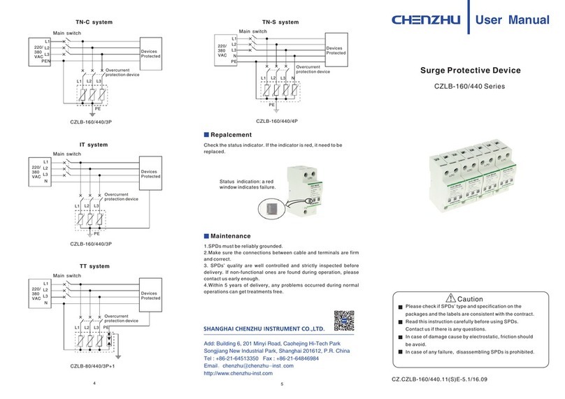
Chenzhu CZLBX-48 Series User manual

Chenzhu

Chenzhu CZLBX-48 Series User manual

Chenzhu CZLBX-48-S Series User manual

Chenzhu

Chenzhu CZLBX-48-S Series User manual

Chenzhu GS8558-EX User manual

Chenzhu

Chenzhu GS8558-EX User manual

Chenzhu CZLB series User manual

Chenzhu

Chenzhu CZLB series User manual

Chenzhu GS8568-EX User manual

Chenzhu

Chenzhu GS8568-EX User manual

Chenzhu GS8515-EX User manual

Chenzhu

Chenzhu GS8515-EX User manual

Chenzhu CZLB-EX Series User manual

Chenzhu

Chenzhu CZLB-EX Series User manual

Chenzhu CZLB-80/440 Series User manual

Chenzhu

Chenzhu CZLB-80/440 Series User manual

Chenzhu CZLB-160/440 Series User manual

Chenzhu

Chenzhu CZLB-160/440 Series User manual

Chenzhu CZLB-160/440 Series User manual

Chenzhu

Chenzhu CZLB-160/440 Series User manual

Popular Surge Protector manuals by other brands

QVS PP134C Specification sheet

QVS

QVS PP134C Specification sheet

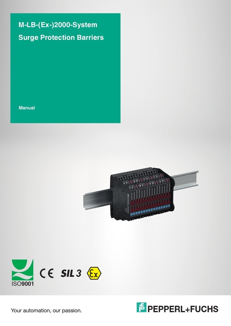
Pepperl+Fuchs M-LB-2000-System manual

Pepperl+Fuchs

Pepperl+Fuchs M-LB-2000-System manual

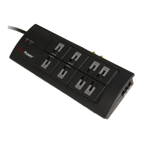
CyberPower 649532008803 Specification sheet

CyberPower

CyberPower 649532008803 Specification sheet

Ditek DTK-110C6A Install instructions

Ditek

Ditek DTK-110C6A Install instructions

Philips SPP1183WC Specification sheet

Philips

Philips SPP1183WC Specification sheet

RVsecure Protector Zero Installation and operating manual

RVsecure

RVsecure Protector Zero Installation and operating manual

M-system MD6 24 Series instruction manual

M-system

M-system MD6 24 Series instruction manual

Total Protection Solutions 80 Operation manual

Total Protection Solutions

Total Protection Solutions 80 Operation manual

UTEK UT-10-12 user manual

UTEK

UTEK UT-10-12 user manual

Philips SPP2307WC Specifications

Philips

Philips SPP2307WC Specifications

Atexor Slam Instructions for safe use

Atexor

Atexor Slam Instructions for safe use

Panamax PM8-GAV installation instructions

Panamax

Panamax PM8-GAV installation instructions

REV'IT Seesmart User information

REV'IT

REV'IT Seesmart User information

Philips SPN5087E/10 user manual

Philips

Philips SPN5087E/10 user manual

Panamax MAX 4310 instructions

Panamax

Panamax MAX 4310 instructions

Eaton PH Series installation instructions

Eaton

Eaton PH Series installation instructions

Patton electronics 570-R8 user manual

Patton electronics

Patton electronics 570-R8 user manual

Intermatic IG1200RC3 installation instructions

Intermatic

Intermatic IG1200RC3 installation instructions

manuals.online logo
manuals.online logoBrands
  • About & Mission
  • Contact us
  • Privacy Policy
  • Terms and Conditions

Copyright 2025 Manuals.Online. All Rights Reserved.