APEX Series | Installation Guide 8
wiring conductors must be sized accordingly dependent upon the following parameters:
If the APEX Series suppressor is positioned within two (2) feet (61 cm.) from the AC power source, then
a minimum of #6 (4.1 mm.) sized wiring conductors are recommended.
If the APEX Series suppressor is positioned within four (4) feet (122 cm.) from the AC power source, then
a minimum of #4 (5.2 mm.) sized wiring conductors are recommended.
CAUTION: Contact Transtector’s Application Engineering Department before proceeding with the
installation if the suppressor cannot be installed within four (4) feet of the AC power source requiring
protection from transient overvoltages.
Step 7:
If a breaker cannot be supplied in the protected panelboard, install either three (3) external fuses or an
external three pole thermal/magnetic circuit breaker to be used as a disconnect in series with the surge
suppressor and the AC power source. Fuses should be rated at ten (10) AMPs less than the service
disconnect to a maximum of 100 AMPS (Typically BUSSMAN LPN Series fuse). A 60 AMP circuit breaker
can be used in conjunction with #6 AWG. (4.1 mm.) sized wire if the surge suppressor is installed within
two (2) feet (61 cm.) of the AC power source. Ensure that the disconnect is installed initially in its “OPEN”
state so that AC power cannot pass through it until it is reset.
CAUTION: The disconnect addressed in the above procedural step serves a dual purpose. It provides a
means for maintenance personnel to de-energize AC power supplied to the APEX Series suppressor to
allow for servicing the device. It also allows the suppressor to be electrically removed from the AC power
source in the event of catastrophic failure modes without disrupting AC power to critical loads. Its current
rating must be rated lower than that of the main disconnect supplying power to the protected electrical
loads.
Step 8:
Route wiring conductors through metal conduit from the disconnect installed in the previous step at the
AC power source to the suppressor enclosure. Mate the conduit to the suppressor enclosure at the hole
bored in Step 4 of the Mechanical Installation procedures on page 3. Ensure that the conduit is properly
grounded at the AC power source.
WARNING: Adequate and proper grounding practices must be heeded to insure that human safety is
accomplished during electrical fault conditions.
Step 9:
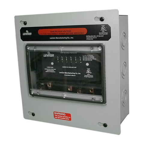
Open the front door of the suppressor enclosure and insure that conduit and/or external grounding
conductors are securely fastened to Ground lug designated with the letter G on the terminal block at
the left side of the backpanel assembly where the three suppressor modules attach. Locate the labeled
terminal block providing the means to attach the electrical wiring conductors from the AC power source
the APEX Series suppressor. The designated labels on the terminal block correspond to specic Phase
and/or Neutral conductors from the AC power wiring positions on the terminal block.
WARNING: In Wye congurations verify that the neutral conductor from the AC power source is connected
properly to the “N” designated position on the terminal block identied in Step 9. If any phase conductor
should accidentally be connected to that “N” designated connection point severe suppressor damage will
result and human safety will be compromised as AC power is applied to the APEX Series suppressor.
Step 10:
After electrical wiring hook-up is complete and prior to energizing electrical power, each suppressor
card must be rmly inserted into it’s respective backpanel slot. Refer to the installation instruction sheet


