PHASE 1
First of all, make sure that the taps of the tanks are closed in a horizontal position and fill the ri ht tank with lead and the left one with powder; also the selectors placed
underneath must be closed in the closed position, and the safety knobs must also be blocked so that when the machine is moved, nothin can escape from the nozzles.
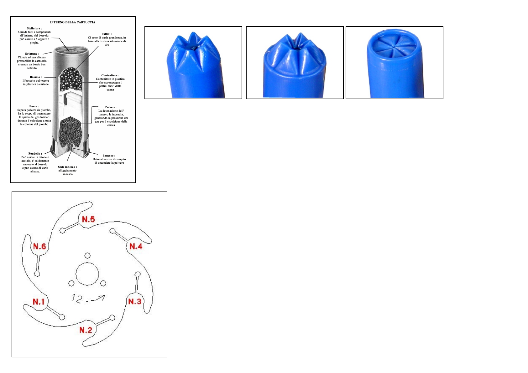
Now we can adjust the hemmin hei ht, insert a new empty case in any station and rotate the disc manually until it is in position (N.5 for 5S press) (N.6 for 6S press)
turn on the motor and lower lever A as far as it will o, to create a round hem. Return the lever to its initial position, in this way we will have the ejection of the cartrid e
from the machine. Usin a measurin au e, check the len th of the case we have obtained, and if it is not the ri ht size, loosen the lockin rin B and adjust the knob C
to (+ -), ti hten the rin a ain lockin . Repeat the operation on the case until we have the desired size.
This is the size of the finished cartrid e; then durin loadin it is possible to vary the hei ht based on the result obtained, as durin all the simultaneous loadin phases,
some dimensions may sli htly vary.
PHASE 2
Let's now pass to the settin of the en raver, that is station N.4
Insert a new case in this station and pull lever A as far as it will o, then turn back. Check the folds on the case and possibly adjust the hei ht usin the re ulator E after
loosenin its rin nut D.
The en ravin on the case must be similar to the one in the photo attached above; if it is more there is a risk of bendin the case, if it is less there could be a hole in the
center of the finished cartrid e closure. It is possible to chan e the hei ht of the en ravin even durin loadin , by adjustin the en raver little by little accordin to the
final result obtained. (Attention: for a correct star closure always use flared cases).
To load new cases, use a steel en raver, while for those already fired it is advisable to use a plastic en raver which favors perfect reali nment with the old en ravin .
PHASE 2 BIS (ONLY FOR SIMPLY 6S VERSION)
Place the case already en raved in station N5, pull lever A as far as it will o, then o back. Check the imprint on the case (as in the fi ure above) and possibly adjust the
hei ht usin its re ulator.
PHASE 3
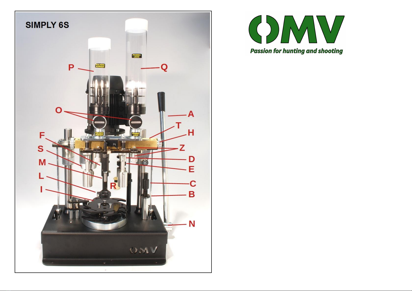
Lead dosa e adjustment placed above station N.3
Insert an empty case into this station; after openin the lead tank tap O and checkin that the sheet Z placed underneath is also open, pull the operatin lever and
dischar e a dose inside the case. Usin the balance, wei h the dose, and consequently act on the H re ulator to chan e the dose if necessary. Repeat the procedure until
the required dose is reached. Attention, before movin on to the next phase and adjustin the powder, it is absolutely necessary to close the lead Z selector, loosenin the
rin nut and movin the foil to the CLOSED position. (Movin the sheet Z in openin or closin it must always be blocked by means of its safety knob placed under it.)
PHASE 4
Powder dosa e adjustment, located above station N.1
Follow the same procedure described in phase 3, adjustin the powder dose usin the left H re ulator, takin into account that each notch corresponds to approximately
0.01 r. (depends on the type of powder you are usin ). It is advisable to et to the ri ht dose radually.
Once the desired dose is reached, set aside a case with the powder inside, which will be used for the next adjustment of the ball pusher.
Close selector Z as described in step 3.
PHASE 5
Wad pusher station (N.2)
To adjust this step, that is the pressure of the wad pusher M on the wad inside the case, it is necessary to use the case with the dose of powder previously set aside.
Insert the cartrid e case in station 2 with the wad we intend to use inside.