Bonny Doon Classic Pro User manual
HYDRAULIC PRESSES AND TOOLING
Classic Pro Manual
20-Ton Press with Handpump

SAFETY WARNINGS & CAUTION
Shipping Crate: Please save the shipping box and plywood blocks with flange for future shipping
The warnings, precautions, and instructions discussed in this
manual cannot cover all possible conditions and situations that may
occur. The operator must understand that common sense and
caution are factors, which cannot be built into this product, but must
be supplied by the operator.
WARNING SYMBOLS AND DEFINITIONS
This is the safety alert symbol. It is used to alert you to
potential personal injury hazards. Obey all safety messages
that follow this symbol to avoid possible serious or Life-Threatening injuries.
Owners Manual and Safety Instructions
1. KEEP WORK AREA CLEAN. Cluttered areas invite injuries.
2. KEEP CHILDREN AWAY. All children should be kept away from work area.
3. DO NOT ASSEMBLE OR OPERATE THE PRESS IF UNDER THE INFLUENCE OF ALCOHOL, OR
DRUGS. Read warning labels on prescriptions to determine if your judgment or reflexes are impaired while taking
drugs. If there is any doubt, do not attempt to assemble or operate.
4. AVOID MOVING PARTS DURING OPERATION. Keep fingers and hands away from all moving parts.
5. USE EYE and FACE PROTECTION. Wear ANSI approved impact safety face and eye protection.
6. DRESS SAFELY. Protective, gloves and non-skid footwear or safety shoes are recommended when working with
and operating the Press. Don't wear loose clothing or jewelry. They can get caught in moving parts. Also, wear a
protective hair covering to prevent long hair from getting caught in the Press.
14. DON'T OVERREACH. Keep proper footing and balance at all times.
.
11. STAY ALERT. Watch what you are doing. Use common sense. Do not operate any tool when you are tired.
12. 20 TON LIMIT. Do not operate the hydraulic jack beyond rated capacity.
13. BOLT PRESS SECURELY TO BENCH.
7. ALWAYS CENTER YOUR WORK, do not press anything off-center. Look at your setup from multiple angles to
insure that everything is centered within the press.
15. REPLACEMENT PARTS AND ACCESSORIES. When servicing, use only identical replacement parts. Only use
Approved accessories intended for use with this Press.
10. DO NOT COMPRESS SPRINGS, do not press cast iron, rocks, or any fragile or brittle objects.
Do not press items that could disengage and cause a potential hazard
Addresses practices not related to personal injury.
Indicates a hazardous situation which, if not avoided,
could result in serious or Life-Threatening injuries.
Indicates a hazardous situation which, if not avoided,
could result in serious or Life-Threatening injuries
12.2
Save this manual: Keep this manual for the safety warnings and precautions, assembly, operating, inspection, cleaning and
maintenance procedures. Keep this manual safe and dry for future reference.
READ ALL SAFETY, ASSSEMBLY AND OPERATING INSTRUCTIONS BEFORE ASSEMBLING OR OPERATING THE
PRESS. FAILURE TO DO SO CAN RESULT IN SERIOUS or LIFE-THREATENING INJURIES.
9. ALWAYS STAND BEHIND THE UPRIGHT COLUMNS OF THE PRESS WHENEVER USING THE
PRESS. INSURE THAT ALL PERSONS ARE LOCATED BEHIND THE COLUMNS WHEN PRESSING.
9. ALWAYS STAND BEHIND THE UPRIGHT COLUMNS OF THE PRESS WHENEVER USING THE
PRESS. INSURE THAT ALL PERSONS ARE LOCATED BEHIND THE COLUMNS WHEN PRESSING.
8. CONTAIN THE DIE AND OBJECTS WHENEVER POSSIBLE, Use form-boxes or silhouette die containers
to contain the urethane and dies.
8. CONTAIN THE DIE AND OBJECTS WHENEVER POSSIBLE, Use form-boxes or silhouette die containers
to contain the urethane and dies.

Identify all Parts
Riser block**
.
Cap head
screws with
hex key for
flange
1/4” T-handle Hex key
**MKIII only
Flange for mounting Cylinder in press frame.
(remove from plywood packaging)
Bolts(2), nuts(4), and
clamps for mounting
to edge of table or for
bolting through
desktop.
Tools Needed
Large Flathead Screwdriver
Adjustable wrench (two may be helpful)
Philips Screwdriver
1.25” tooling bolt
5/16” hex key
for Hand
Pump

Pro Manual Hand-pump
12.2
6ft hose with quick connect included
gauge
pump handle
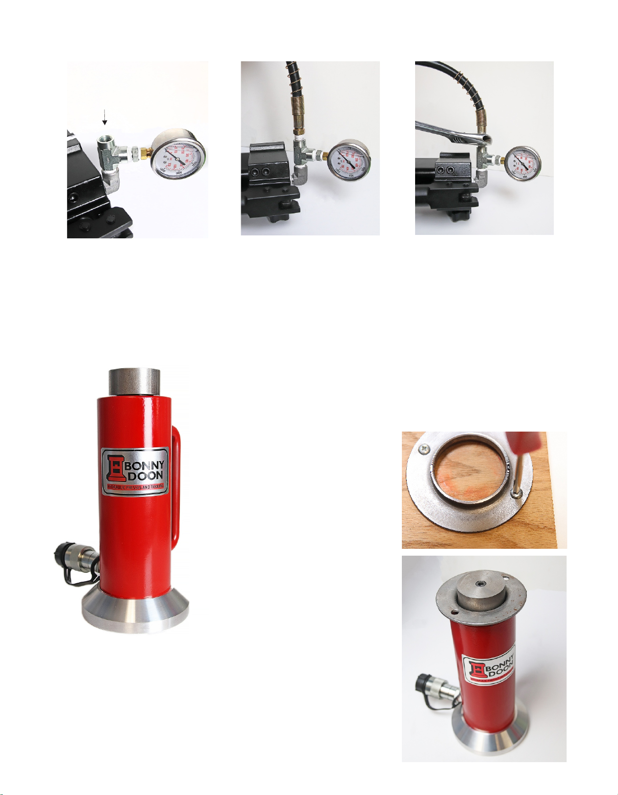
Connecting the Hose
You may want to use some rags
to put under the handpump so it
wont tip over.
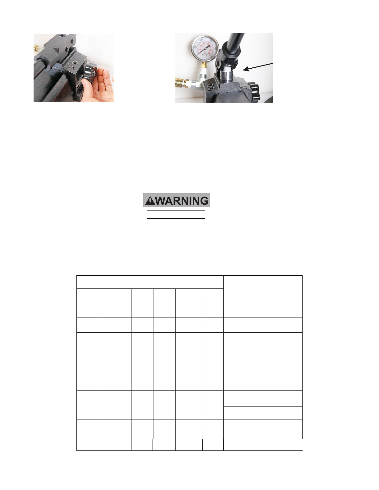
Start by turning the handpump
on its side so the hex plug is
facing up as shown.
Have some paper towels ready
in case any oil leaks. Use the
included 5/16 hex key to un-
thread the plug.
Continued on next page--->
threaded end
w/ teflon
pressure release
knob
reservoir fill plug
Place the flange on top of
your cylinder. The flange
will be attached to the
press platen, keeping your
cylinder centered and
secure in the press.
-------->
Continued on next page.
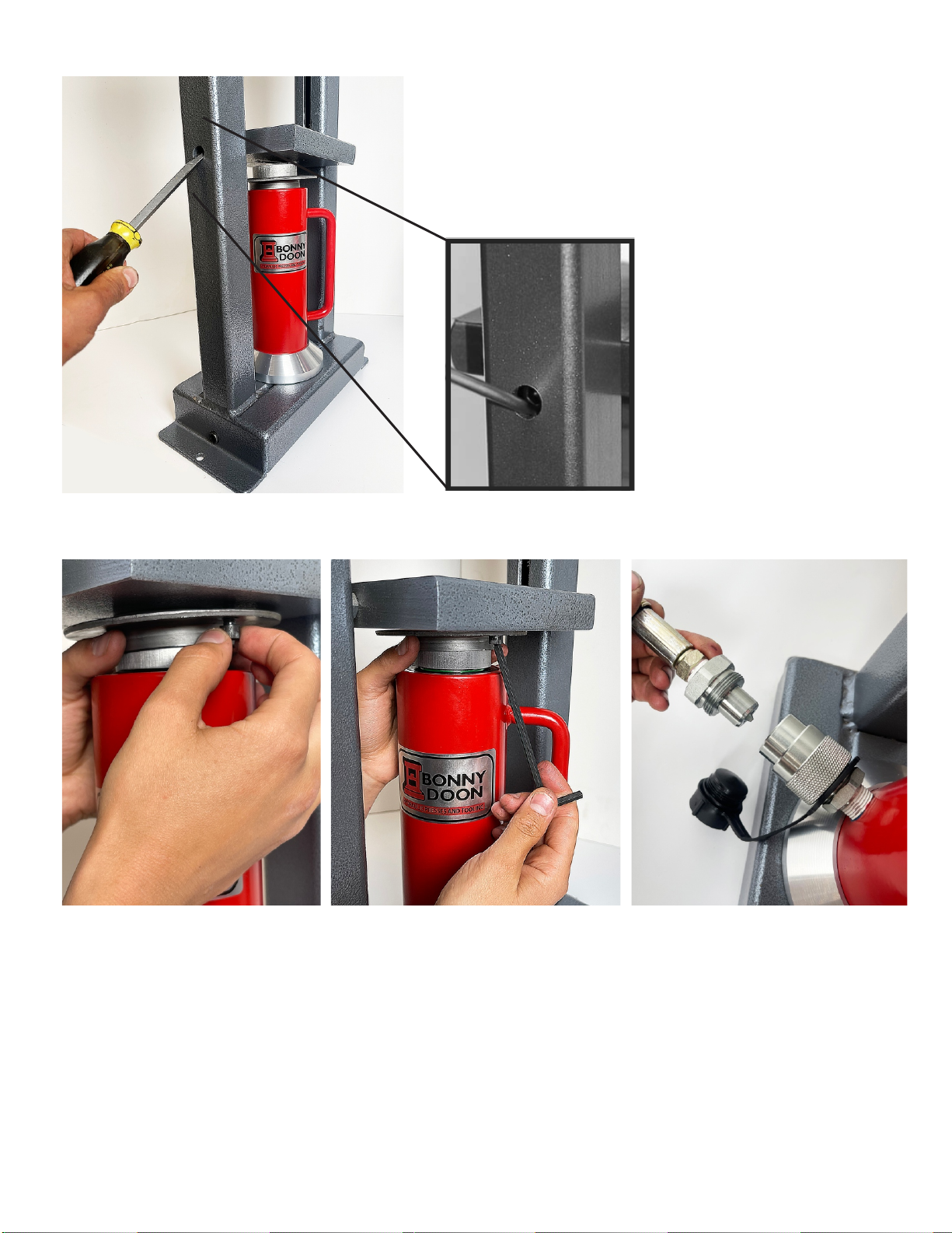
Place screwdriver under the head of
the bolt and pry bolt upwards to
make room for the ram. Gently lower
the platen onto the ram head.
Close up of platen bolt, DO NOT
UNSCREW BOLT.
Remove the plug so that
you can now connect the
hose.
Carefully thread the end of
the hose w/ teflon into the
fitting. You will need to turn
the entire hose to do so.
Make sure it goes in straight
and square and you get at
least two threads engaged.
Once the hose has been
threaded in a few turns
you can use your
adjustable wrench to
tighten the fitting with
firm pressure. Use a
second wrench on the T-
fitting to assist in
tightening this
connection.
Installing the Cylinder
Using a Philips
Screwdriver, remove the
screws holding the flange
to the plywood
packaging. Replace
screws in plywood and
keep packaging.
Our new Pro cylinder is a robust
hydraulic cylinder with easy to
use quick connect plumbing. The
stroke is 5.91” and cannot be
overextended. This cylinder can
be easily connected to a manual
hand-pump or electric pump.
Close up of platen bolt,
pry this up to assist in
placing the ram into
the center of the
frame.
Use your flathead screwdriver to pry up the press
platen so you can place the hydraulic cylinder. Make
sure to place the tip of the screwdriver under the
bolt. Do not ever remove or loosen this bolt. Notice
on the underside of the platen will be two threaded
holes. Make sure to orient these holes facing down.
Center the cylinder in the press
and line up the two threaded
holes with the flange. Use the
included 1/4-20 x 1/2” long
screws to attach the flange to
the platen.
platen
Use the included 3/16” hex key to
tighten both bolts to the platen.
Continued on next page ------>
Now you are ready to connect
the pump to the cylinder. Start
by unscrewing the black plastic
caps from both ends.

Push the two ends of the quick
connect together.
While pushing them together
thread the sleeve on the
cylinder end over the threads
on the hose end. You only want
to tighten this fitting by hand.
Make sure that the fitting is
tight and that there is no gap
in between them. Do not use
any tools to tighten this fitting.
With this easy to use quick connect fitting you can switch between an electric pump and a manual
pump within about 15 seconds. This setup would give you the best combo of speed (electric
pump) and precision control when you need finesse (manual handpump)
Securing the Press
You will want to securely attach your press to your workbench top. The press frame has pre-drilled
holes to be used with lag bolts or through bolts depending upon your workbench material. The
Pro Manual Hand pump comes with clamps to secure it to the edge of a workbench top, or you
can use the bolts to bolt it directly onto your bench top.
Start by putting the bolt
through the holes in the
hand pump and secure with
a nut so it is tight on the
handpump base.
Add the aluminum clamp
block on the bottom and
secure with the second nut.
Tighten this down with your adjustable
wrench.
The ram should be lowered all the way down at the end of each day’s use. This keeps the ram clean and free of
dust and debris which wears on the seals.
Manual Handpump: Check the level through the reservoir fill plug hole with the ram all the way down. The
level should be 1/2” below the bottom of the reservoir fill plug hole. You can use a paperclip or toothpick to
check the level. Only use “Hydraulic Oil, AW-46”.
Clean: Clean the press and ram by using a clean cloth with a detergent or mild cleaner. Store and use the press
in a well protected area free of corrosive vapors, abrasive dust, and harmful elements. Keep all warning labels
clean and legible.
Oil Level: The oil level is topped off when shipped. It may leak during transport. All hydraulics leak over time
and use, if your press is leaking more than a tablespoon per week then it is in need of repair. If it is leaking less
than a tablespoon per week it is within the normal limits of use. Do Not overfill the Pro Manual Hand pump,
it needs some air in the reservoir to function properly.
Change the oil at least once a year. The first oil change should be performed no more than 12 months after
purchase, change every 6-12 months thereafter, more frequently with heavy use.
Save all warnings and instructions for future reference.
Cleaning, Maintenance, and Lubrication
Before each use, inspect the general condition of the Press and Ram. Check for broken, cracked, or bent parts,
loose or missing parts, and any condition that may affect the proper operation of the product. If a problem
occurs, it may have an effect on the proper operation of the product. If a problem occurs, have the problem
corrected before further use.
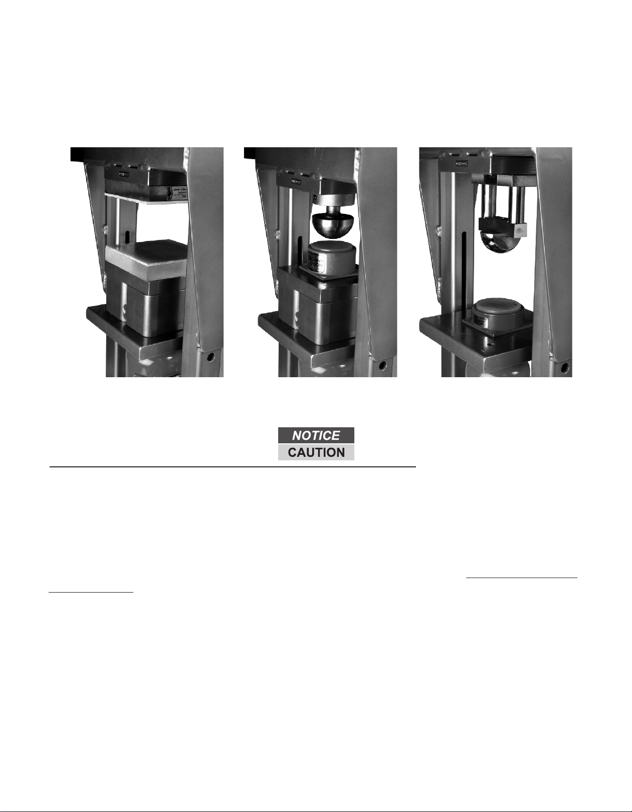
The Classic press allows for up to 7” of space between the two platens, the MKIII allows for 10” between the
two platens. This accommodates many of the large Bonny Doon tools such as the bracelet formers and the
deep-draw kits. On the MkIII you will want to use the riser block for most operations.
Always use a minimum of 2” of tooling in the press. The ram is designed to move no more than 5.91” For
thin operations such as blanking dies or embossing with pattern plates you will need aluminum spacers to
take up the extra space. All three of the images below have at least 2” of tooling.
Shown with 2” of
spacer blocks
Shown with Master tool
holder, Mushroom
Shown with Bracelet
forming kit.
Always use a minimum of 2” of tooling in the press.
Troubleshooting
POSSIBLE SYMPTOMS PROBABLE SOLUTION
(Make certain that the ram is
not supporting a load while
not push to
its force
capacity
Cylinder
lowers
under load
Pump
stroke
feels
spongy
Cylinder
will not
lift all
the way
Oil
leaking
from
filler
plug
Xcheck that Release Valve Knob
Xis closed fully.
XX
Valves may be blocked and may not
X
close fully. To flush the valves:
1. Lower the Platen and securely
close the Release Valve.
2. Manually lift the platen
several inches.
3. Open the release valve
and let the platen down
as quickly as possible.
XX
ram may be low on oil. Check
Xthe oil level and refill if needed.
Ram may require bleeding - see
instructions above .
Unit may have too much
Xhydraulic oil inside, check fluid
level and adjust if needed.
IMPORTANT!
3. Pump the pump handle and raise the platen most of the way up.
6. Re-tighten the Oil Filler Plug.
2. Tighten the Pressure Release Knob.
1. Slightly loosen the Oil Filler Plug.
To remove excess air from hydraulic system:
Before first use, check for proper hydraulic oil level in the pump. It should be filled no more than 1/2” below the level of the Oil
Filler hole. There must be some air in the pump reservoir for it to work properly. Then thoroughly test the press for proper
operation prior to its actual use. If the cylinder and pump appears not to be working properly it may be necessary to bleed its
hydraulic system of excess air.
5. Test several times by tightening the Pressure Release Valve and raising the lower platen 2-4 inches and releasing.
4. Undo the Pressure Release Knob 1/2 turn or so, lowering the platen all the way down.
If after purging the press still does not operate properly do not use press until it has been repaired or replaced by a qualified service
technician.
X X
It is normal to have
small amounts of oil
around the cylinder
here. You may even get
some small droplets of
oil on your workbench.
X
attempting a solution)
Cylinder will Oil leaking
from
connections
XTighten connections
Pressure Release
Knob - open and
close only 1/2
turn
If the solutions presented in the Troubleshooting guide do not solve the problem, have a
qualified technician inspect and repair the Press before use. After the ram is repaired:
Test it carefully without a load by raising it and lowering it fully, checking for proper
operation, BEFORE RETURNING THE PRESS TO OPERATION.
TO PREVENT SERIOUS INJURY: Use caution when troubleshooting a malfunctioning
Press. Completely resolve all problems before use.
Do not use a damaged or malfunctioning press.
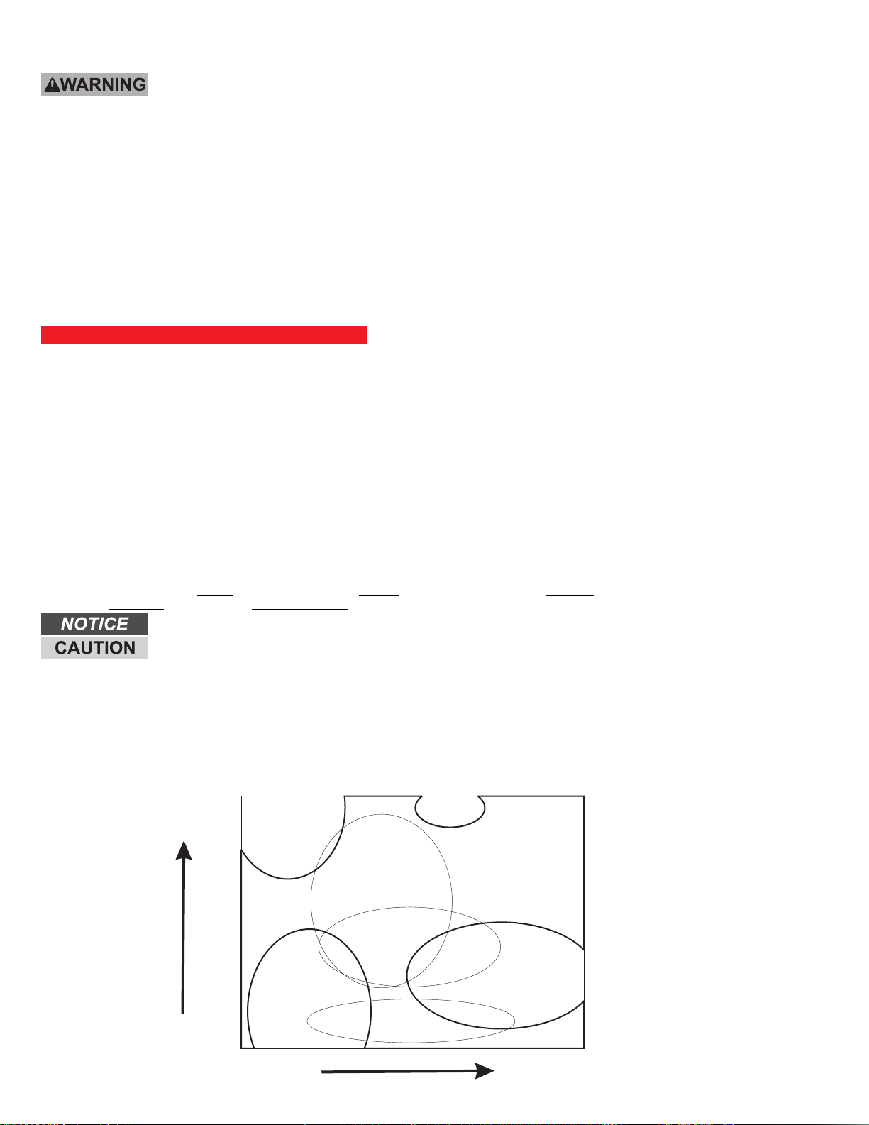
Simple Complex
Silhouette dies Conforming dies
Non-conforming dies
Coining
High Pressure
Low pressure
Blanking dies
Complexity of die
Pressure Requirement
Embossing
Deep-drawing
Always use the least amount of pressure or force to obtain the desired results
ALWAYS CENTER THE WORK. Use of the tooling holes will automatically do this for you. If using matrix dies, or blanking dies, place
them in the center of the platen because you will get a more even impression, and the platen will not tilt under pressure.
1. Never get in a hurry!
4. Remember the 5 “C’s”, Cover your face and eyes, Center your work in the press, Contain the work whenever possible, stand
behind the Columns, and exercise Common Sense.
UNDERSTAND FORCE and SURFACE AREA: the smaller the surface area of a punch the more force is
applied at the point of contact. The 20 ton rating on this press is in reference to 1 square inch. In other words, if
you place 20 tons of force on 1 square inch of work you will get 20 tons per square inch (40,000 pounds per sq
inch). If 20 tons of force is applied to a workpiece or a punch with an area of only ½ square inch then the force
applied to that workpiece or punch will be equal to 80 tons. This is far beyond the material limits of many metals
including steel and may represent a dangerous condition. Understand the material properties of each item you
are placing in the press. Consequently if you exert 20 tons of force on a workpiece of 10 square inches then you
are exerting only 2 tons of force per square inch of workpiece.
DO NOT EXCEED THE PROPER PRESSURE FOR THE JOB. See chart below for ranges of pressures for various processes. Avoid
using small surface-area punches such as small daps and punches.
3. Exercise thought before pumping the press!
NEVER TRY TO EMBOSS OR USE BLANKING DIES WITHOUT THE TOP SPACER/S.The top spacer is to make the tooling holes "go
away". These holes can damage your die. You will want to use aluminum spacers for thin work such as blanking dies and embossing with
pattern plates. The cylinder has a stroke of 5.91” so it will not go all the way to the top.
ALWAYS BOLT TOOLING IN PLACE. NEVER use a cast spoon stake in the press. The cast stakes are not designed for use in any
press. They are cast iron and will shatter and/or eject out of the press. Tooling attachment holes are in the top platen of the press for this
reason. Only use tooling designed for use in a hydraulic press.
ASSEMBLE YOUR WORK ON A PALLET AND SLIDE THE PALLET INTO THE PRESS. This allows you to locate everything without
disturbing your assembly. The way I describe this in the workshops is that "it is easier to assemble the pizza on a pan and slide the whole
works into the oven, rather than trying to assemble the whole thing in the oven.
(The “pallet” is usually a platen protector or aluminum spacer)
ALWAYS LOWER THE RAM WHEN FINISHED FOR THE DAY. The ram is slightly oily and an excellent dust and grit magnet. Abrasive
grit, corrosive vapors, dust and other harmful substances are to be avoided. When not in use, lower the ram back into its protective
sheath.
Tips for Using your Hydraulic Press
2. Use the proper tool for the job!
ALWAYS WEAR SAFETY GLASSES OR A FACE SHIELD. Things can always break under the pressures that you are working with.
Cast Acrylic will withstand incredible pressure if it is fully supported on the back side, but if it is hanging over the edge, and the urethane
pad starts to bend the area that is hanging over it is sure to break. Do not use small daps or punches with urethane pads. This will ruin
the pad by cutting it, and the punch can also eject out of the press if pressure was excessive, the punches are for use with the contained
block of urethane or forming box. See “Understanding PSI and Surface Area” below.
12.2
Table of contents


