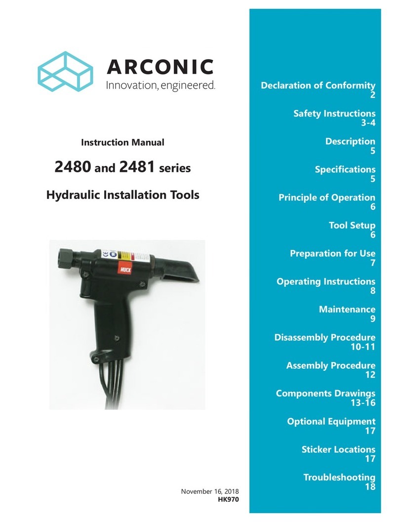
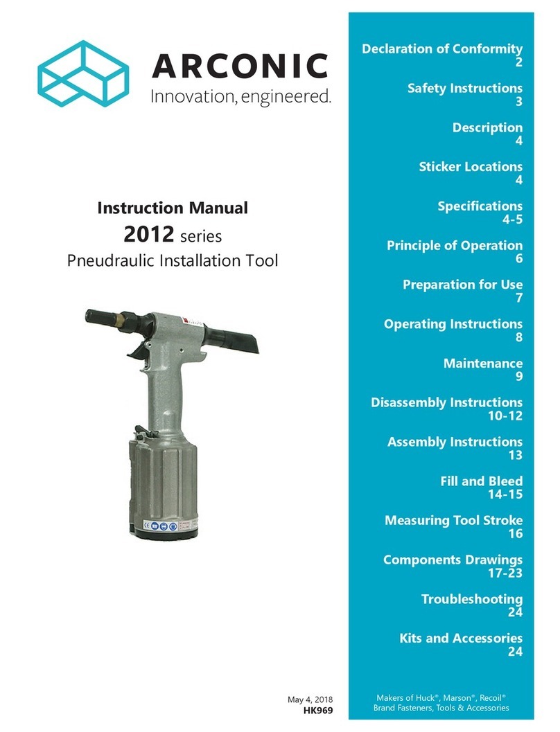
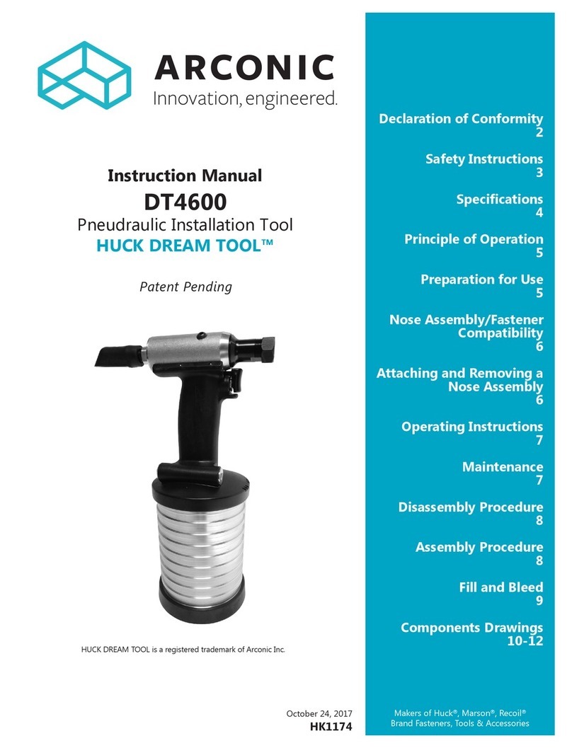
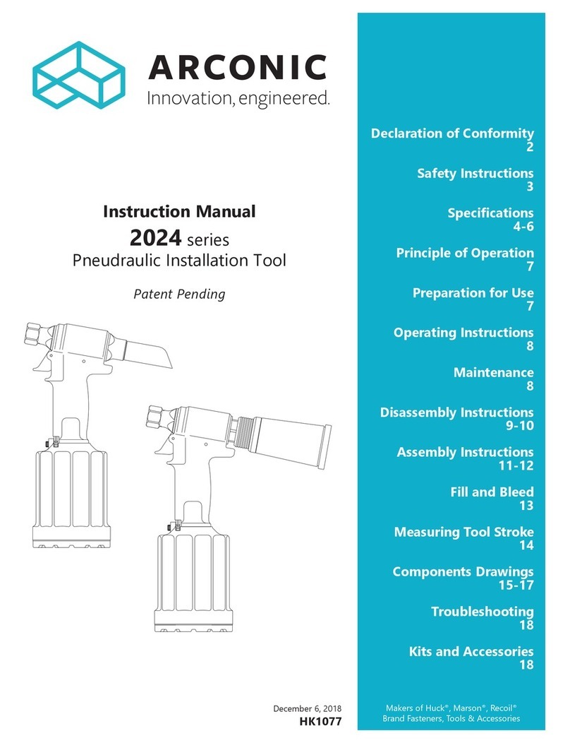
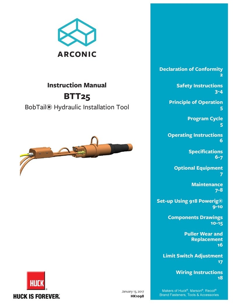
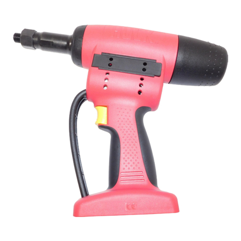
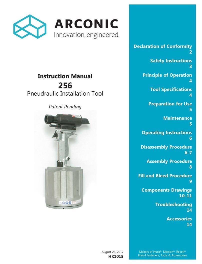
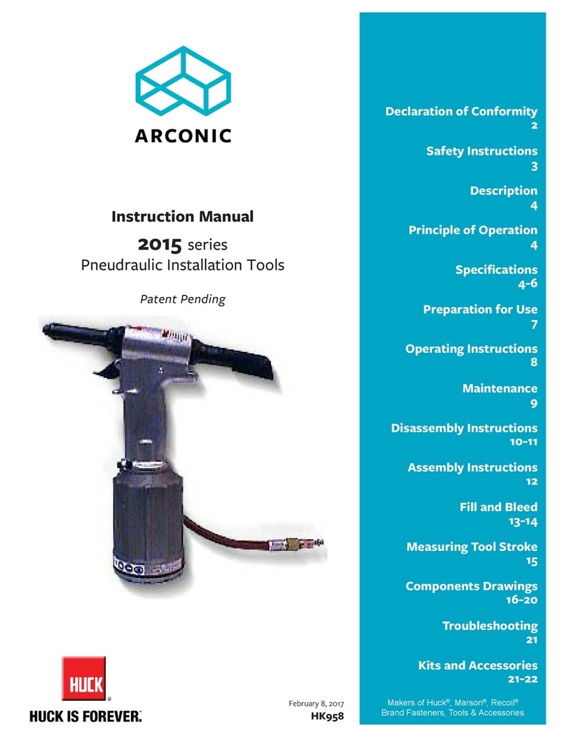
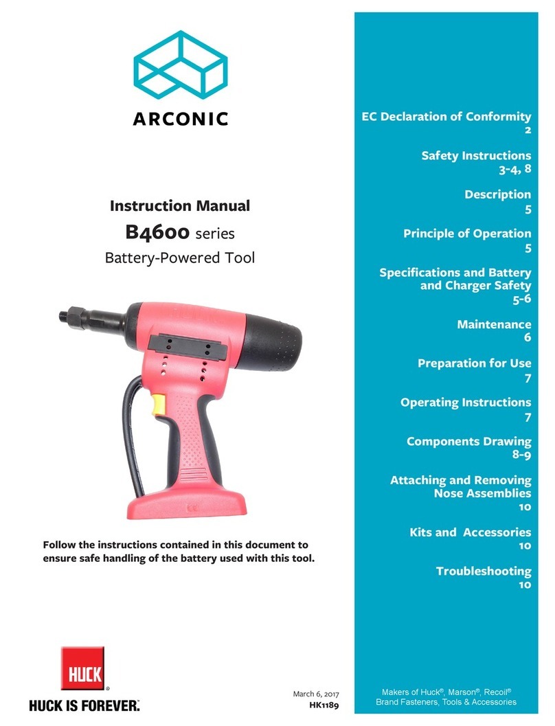
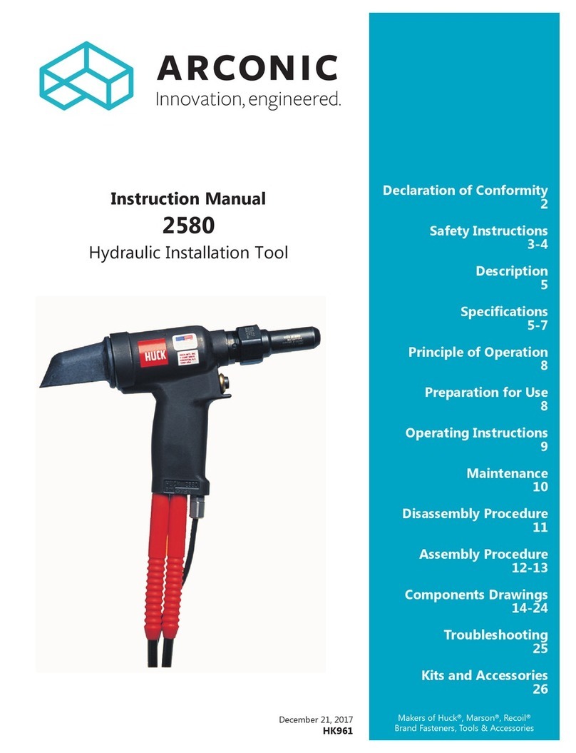
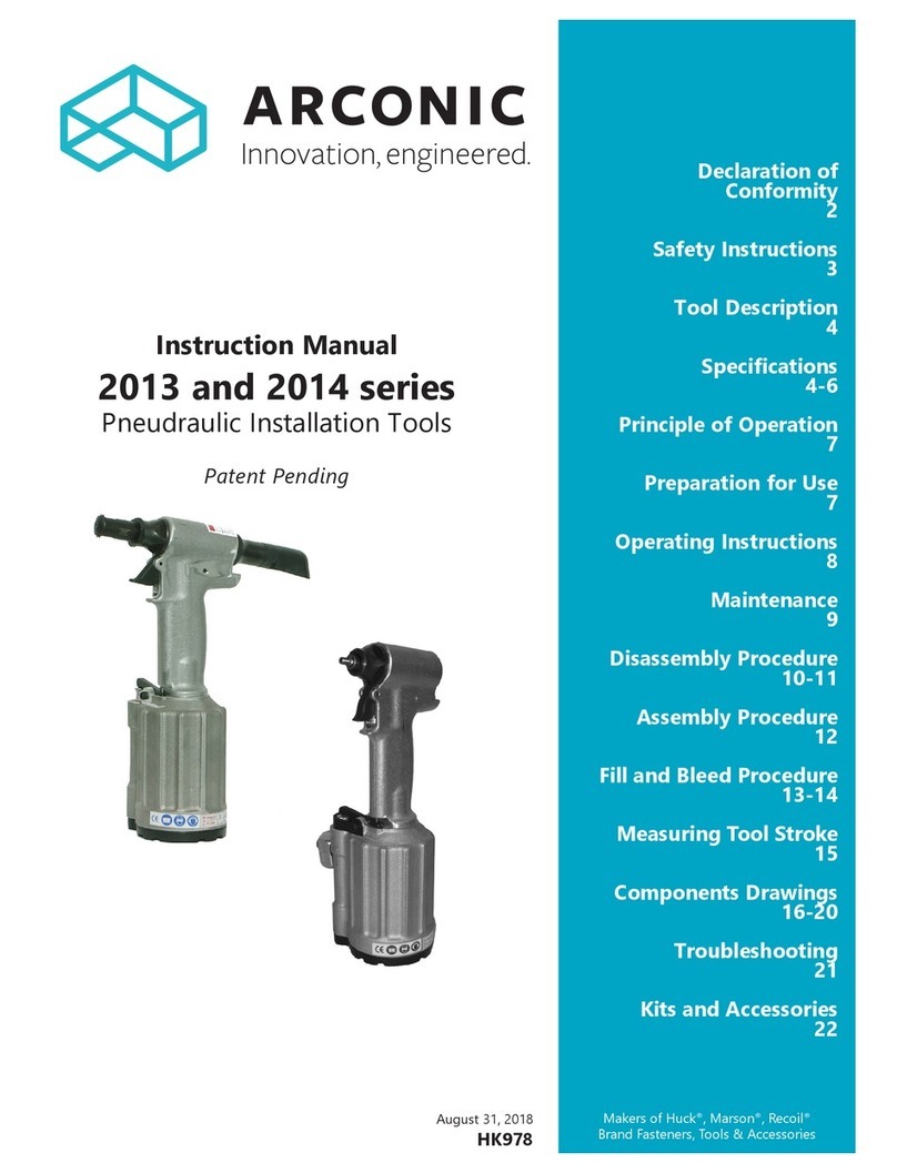
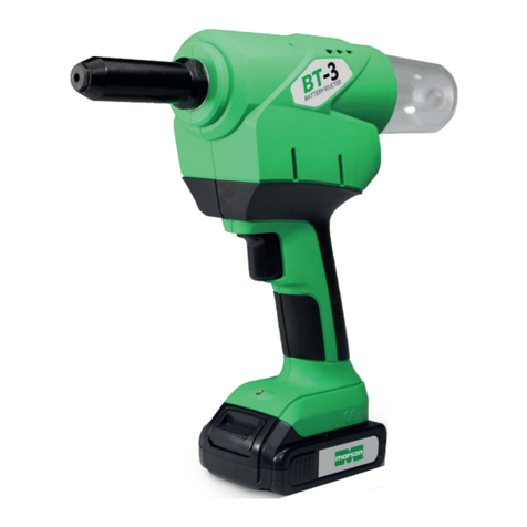
Arconic 244BT User manual

Patent Pending
September 18, 2017
HK1113
Makers of Huck®, Marson®, Recoil®
Brand Fasteners, Tools & Accessories
Declaration of Conformity
2
Safety Instructions
3
Description
4
Specications
4
Principle of Operation
5
Preparation for Use
5
Operating Instructions
6
Measuring Tool Stroke
7
Maintenance
7
Disassembly Procedure
8-9
Assembly Procedure
10-11
Fill and Bleed Procedure
12
Tool Components
Drawings
13-15
Troubleshooting
16
Kits and Accessories
16
Instruction Manual
244BT
Pneudraulic Installation Tool

244BT Pneudraulic Installation Tool (HK1113)
2

244BT Pneudraulic Installation Tool (HK1113)
3
I. GENERAL SAFETY RULES:
1.Ahalfhourlonghands-ontrainingsessionwithqualiedpersonnelis
recommendedbeforeusingHuckequipment.
2.Huckequipmentmustbemaintainedinasafeworkingconditionatall
times.Toolsandhosesshouldbeinspectedatthebeginningofeach
shift/dayfordamageorwear.Anyrepairshouldbedonebyaqualied
repairmantrainedonHuckprocedures.
3.Formultiplehazards,readandunderstandthesafetyinstructionsbefore
installing,operating,repairing,maintaining,changingaccessorieson,
orworkingneartheassemblypowertool.Failuretodosocanresultin
serious bodily injury.
4.Onlyqualiedandtrainedoperatorsshouldinstall,adjustorusethe
assemblypowertool.
5.Donotmodifythisassemblypowertool.Thiscanreduceeffectivenessof
safetymeasuresandincreaseoperatorrisk.
6.Donotdiscardsafetyinstructions;givethemtotheoperator.
7.Donotuseassemblypowertoolifithasbeendamaged.
8.Toolsshallbeinspectedperiodicallytoverifyallratingsandmarkings
required,andlistedinthemanual,arelegiblymarkedonthetool.The
employer/operatorshallcontactthemanufacturertoobtainreplacement
markinglabelswhennecessary.Refertoassemblydrawingandpartslist
forreplacement.
9. Tool is only to be used as stated in this manual. Any other use is
prohibited.
10.ReadMSDSSpecicationsbeforeservicingthetool.MSDS
specicationsareavailablefromtheproductmanufactureroryourHuck
representative.
11.OnlygenuineHuckpartsshallbeusedforreplacementsorspares.Use
ofanyotherpartscanresultintoolingdamageorpersonalinjury.
12.Neverremoveanysafetyguardsorpintaildeectors.
13.Neverinstallafastenerinfreeair.Personalinjuryfromfastenerejecting
may occur.
14.Whereapplicable,alwaysclearspentpintailoutofnoseassembly
before installing the next fastener.
15.Checkclearancebetweentriggerandworkpiecetoensurethereisno
pinchpointwhentoolisactivated.Remotetriggersareavailablefor
hydraulictoolingifpinchpointisunavoidable.
16.Donotabusetoolbydroppingorusingitasahammer.Neveruse
hydraulicorairlinesasahandleortobendorprythetool.Reasonable
careofinstallationtoolsbyoperatorsisanimportantfactorin
maintainingtoolefciency,eliminatingdowntime,andpreventingan
accidentwhichmaycauseseverepersonalinjury.
17.Neverplacehandsbetweennoseassemblyandworkpiece.Keephands
clear from front of tool.
18.Toolswithejectorrodsshouldneverbecycledwithoutnoseassembly
installed.
19.Whentwopiecelockboltsarebeingusedalwaysmakesurethecollar
orientationiscorrect.Seefastenerdatasheetforcorrectpositioning.
II. PROJECTILE HAZARDS:
1.Riskofwhippingcompressedairhoseiftoolispneudraulicorpneumatic.
2.Disconnecttheassemblypowertoolfromenergysourcewhenchanging
inserted tools or accessories.
3.Beawarethatfailureoftheworkpiece,accessories,ortheinsertedtool
itselfcangeneratehighvelocityprojectiles.
4.Alwayswearimpactresistanteyeprotectionduringtooloperation.The
gradeofprotectionrequiredshouldbeassessedforeachuse.
5. The risk of others should also be assessed at this time.
6.Ensurethattheworkpieceissecurelyxed.
7.Checkthatthemeansofprotectionfromejectionoffastenerorpintailis
inplaceandoperative.
8.Thereispossibilityofforcibleejectionofpintailsorspentmandrelsfrom
front of tool.
III. OPERATING HAZARDS:
1.Useoftoolcanexposetheoperator’shandstohazardsincluding:
crushing,impacts,cuts,abrasionsandheat.Wearsuitableglovesto
protecthands.
2.Operatorsandmaintenancepersonnelshallbephysicallyabletohandle
thebulk,weightandpowerofthetool.
3. Hold the tool correctly and be ready to counteract normal or sudden
movementswithbothhandsavailable.
4.Maintainabalancedbodypositionandsecurefooting.
5.Releasetriggerorstopstartdeviceincaseofinterruptionofenergy
supply.
6.Useonlyuidsandlubricantsrecommendedbythemanufacturer.
7.Avoidunsuitablepostures,asitislikelyforthesenottoallow
counteractingofnormalorunexpectedtoolmovement.
8.Iftheassemblypowertoolisxedtoasuspensiondevice,makesurethat
xationissecure.
9.Bewareoftheriskofcrushingorpinchingifnoseequipmentisnottted.
IV. REPETITIVE MOTION HAZARDS:
1.Whenusingassemblypowertool,theoperatorcanexperience
discomfortinthehands,arms,shoulders,neckorotherpartsofthebody.
2.Whenusingtool,theoperatorshouldadoptacomfortableposture
whilemaintainingasecurefootingandavoidawkwardoroffbalanced
postures.
3.Theoperatorshouldchangepostureduringextendedtaskstohelpavoid
discomfort and fatigue.
4.Iftheoperatorexperiencessymptomssuchaspersistentorrecurring
discomfort,pain,throbbing,aching,tingling,numbness,burning
sensationsorstiffness,thesewarningsshouldnotbeignored.The
operatorshouldtelltheemployerandconsultaqualiedhealth
professional.
V. ACCESSORIES HAZARDS:
1.Disconnecttoolfromenergysupplybeforechanginginsertedtoolor
accessory.
2.Useonlysizesandtypesofaccessoriesandconsumablesthatare
recommended.Donotuseothertypesorsizesofaccessoriesor
consumables.
VI. WORKPLACE HAZARDS:
1.Beawareofslipperysurfacescausedbyuseofthetoolandoftrip
hazardscausedbytheairlineorhydraulichose.
2.Proceedwithcautionwhileinunfamiliarsurroundings;therecouldbe
hiddenhazardssuchaselectricityorotherutilitylines.
3.Theassemblypowertoolisnotintendedforuseinpotentiallyexplosive
environments.
4.Toolisnotinsulatedagainstcontactwithelectricalpower.
5.Ensuretherearenoelectricalcables,gaspipes,etc.,whichcancausea
hazardifdamagedbyuseofthetool.
VII. NOISE HAZARDS:
1.Exposuretohighnoiselevelscancausepermanent,disablinghearing
lossandotherproblemssuchastinnitus,thereforeriskassessmentand
theimplementationofpropercontrolsisessential.
2.Appropriatecontrolstoreducetheriskmayincludeactionssuchas
dampingmaterialstopreventworkpiecefrom‘ringing’.
3.Usehearingprotectioninaccordancewithemployer’sinstructionsandas
requiredbyoccupationalhealthandsafetyregulations.
4.Operateandmaintaintoolasrecommendedintheinstructionhandbook
topreventanunnecessaryincreaseinthenoiselevel.
5.Select,maintainandreplacetheconsumable/insertedtoolas
recommendedtopreventanunnecessaryincreaseinnoise.
6.Ifthepowertoolhasasilencer,alwaysensurethatitisinplaceandin
goodworkingorderwhenthetoolisbeingoperated.
VIII. VIBRATION HAZARDS:
1.Exposuretovibrationcancausedisablingdamagetothenervesand
bloodsupplytothehandsandarms.
2.Wearwarmclothingwhenworkingincoldconditionsandkeephands
warm and dry.
3.Ifnumbness,tingling,painorwhiteningoftheskininthengersor
hands,stopusingthetool,tellyouremployerandconsultaphysician.
4.Supporttheweightofthetoolinastand,tensionerorbalancerinorder
tohavealightergriponthetool.
IX. PNEUMATIC / PNEUDRAULIC TOOL SAFETY INSTRUCTIONS:
1.Airunderpressurecancausesevereinjury.
2.Alwaysshutoffairsupply,drainhoseofairpressureanddisconnecttool
fromairsupplywhennotinuse,beforechangingaccessoriesorwhen
makingrepairs.
3.Neverdirectairatyourselforanyoneelse.
4.Whippinghosescancausesevereinjury,alwayscheckfordamagedor
loosehosesandttings.
5. Cold air should be directed away from hands.
6.Wheneveruniversaltwistcouplings(clawcouplings)areused,lockpins
shallbeinstalledandwhip-checksafetycablesshallbeusedtosafeguard
againstpossiblehosetohoseorhosetotoolconnectionfailure.
7.Donotexceedmaximumairpressurestatedontool.
8.Nevercarryanairtoolbythehose.
Safety Instructions
GLOSSARYOFTERMSANDSYMBOLS:
- Productcomplieswithrequirementssetforthby
therelevantEuropeandirectives.
- Readmanualpriortousingthisequipment.
- Eyeprotectionisrequiredwhileusingthis
equipment.
- Hearingprotectionisrequiredwhileusingthis
equipment.
Notes:areremindersofrequiredprocedures.
Bold, Italic type, and underline:emphasizeaspecic
instruction.
WARNINGS: Must be understood to avoid
severe personal injury.
CAUTIONS: Show conditions that will damage
equipment or structure.
244BT Pneudraulic Installation Tool (HK1113)
4
Tool Specications
.72
1.8
5.99
15.2
4.12
10.5
.78
2
12.8
32.5
4.76
12.1
10°
4.10
10.4
1.56
3.9
ø
1.44
3.7
ø
3.72
9.5
INCHES
cm
POWER SOURCE:90psishopair
MAX OPERATING TEMP:125°F(51.7°C)
MAX FLOW RATE:6.3scfm(178l/m)
MAX AIR PRESSURE:100psi(6.9bar)
MIN PULL CAPACITY:
2350lbf(10.5kN)@90psi
MIN STROKE:1.032inches(2.62cm)
SPEED/CYCLES:30perminute
WEIGHT:6.31lbs(2.86kg)
POWER SOURCE:90-100psishopair
HYDRAULIC FLUID:Hydraulicuid
shallmeetDEXRONIII,DEXRONVI,
MERCON,AllisonC-4orequivalentATF
specications.
Fireresistantuidmaybeusedifitisan
esterbaseduidsuchasQuintolubric
HFDorequivalent.Waterbaseduid
shall NOT be used as serious damage to
equipmentwilloccur.
Tool Nominal psi +/- 2 Nominal Tool Stroke Capacity Minimum Stroke
244BT-43 43 1150 lbs. .943 in.
244BT-68 68 1810 lbs. .943 in.
244BT-85 85 2270 lbs. .943 in.
244BT-97 97 2580 lbs. .943 in.
Description
The244BTisalightweightpneudraulicinstallation
toolintendedforpullingthefastenerslistedbelowin
conjunctionwiththeapplicablenoseassemblyand
pressureregulator.244BTmodelsaresoldwiththe
specicpressureregulatorrequiredforthefastenerto
be installed.
-06BT(3/16”)Grade2
-08BT(1/4”)6061Aluminum
-08BT(1/4”)Grade2
-08BT(1/4”)430SS
-10BT(5/16”)6061Aluminum
AtableinFigure16outlinesthetool-regulator,
fastener,andnoseassemblycombinationsnecessaryfor
application.
CAUTION: Using a pressure regulator not
intended for a specic fastener can result
in damage of equipment and fasteners and
improper and unsafe installation of fasteners.
Where the following trade names are used in this
manual, please note:
DEXRON is a registered trademark of General Motors Corporation.
Loctite is a registered trademark of Henkel Corporation, U.S.A.
LUBRIPLATE is a registered trademark of Fiske Brothers Rening Co.
MERCON is a registered trademark of Ford Motor Corp.
Never-Seez is a registered trademark of Bostik, Inc.
Quintolubric is a registered trademark of Quaker Chemical Corp.
Slic-tite is a registered trademark of LA-CO Industries, Inc.
Teon is a registered trademark of E. I. du Pont de Nemours and
Company.
Threadmate is a registered trademark of Parker Intangibles LLC.
TRUARC is a trademark of TRUARC Co. LLC.
Vibra-Tite is a registered trademark of ND Industries, Inc. USA.

244BT Pneudraulic Installation Tool (HK1113)
5
10
11
3
4
Spring
8
Pressurized Air
Exhaust Air
1
2
12
5
6
9
7
Pressurized Hydraulic Fluid Non-pressurized Hydraulic Fluid
Air Piston
moves up
Exhaust Air
Throttle Valve
moves down to
(PULL position)
Exhaust Air
Pull Piston
moves back
Rod and
Hydraulic Piston
move up
Trigger
Depressed
Throttle Valve
moves up to
RETURN position
Trigger
Released Pull Piston
returns to
home position
Air Piston
moves
down
Pressurized Air
Exhaust Air
PULL: Whenthetriggerisdepressed(1),
thethrottlevalvemovestodownposition
(2),andpressurizedairisdirectedtothe
bottomoftheairpiston,causingthe
pistontomoveupward(3).Theairabove
thepistonisexhaustedanddirected
throughthecenterofthethrottlevalve
andoutthebottomofthetool(4).Asthe
airpistonmovesupward,theattached
rodandhydraulicpistonandareforced
up(5),andacolumnofpressurizeduid
isforcedintothehead,whichmoves
thehydraulicpullpistonback(6).The
attachednoseassemblymoveswiththe
hydraulicpullpistontobeginfastener
installation.
RETURN: When fastener installation is
completed,thetriggerisreleased(7).Air
pressure,withtheassistanceofaspring
(8),causesthethrottlevalvetoreturn
toitsupposition(9).Pressurizedairis
redirectedtothetopoftheairpiston,
causingittomovedownward(10).The
airfrombelowthepistonisexhausted
throughbottomoftool(11).Astherod
andairpistonmovedownward,hydraulic
pressureisreversedandthehydraulic
pullpistonisreturnedforward(12).The
returnpressurereliefvalveprotectsthe
toolagainstpressurespikes.Thereservoir
replenishesthehydraulicsystemas
needed.
Principle of Operation
1. Removeplasticshippingplugfromair
hoseandputinafewdropsofAutomatic
TransmissionFluid,DEXRONIII,orequivalent.
2. ScrewquickdisconnectttingintoAirInlet
Connector.
3. Setairpressureonregulatorto10psiabove
theattachedregulatorsetpoint.
4. Attachairhosetoairpowersource.
5. Cycletoolafewtimesbydepressingand
releasing trigger.
6. Disconnect air hose from tool.
7. RemoveRetainingNutandStop.
8. SelectproperNoseAssemblyforfastenerto
be installed.
9. Attach Nose Assembly.
10. Connectairhosetotoolandinstallfastener(s)
intestplateofproperthicknesswithproper
sizeholes.Inspectfastener(s).
NOTE:
Air quick disconnect ttings and air hoses
are not available from Huck International,
Inc.
WARNINGS:
Read full manual before using tool.
Inspect tool for damage or wear before each use. Do not
operate if damaged or worn, as severe personal injury
may occur.
A half-hour training session with qualied personnel is
recommended before using Huck equipment.
When operating Huck installation equipment, always
wear approved eye protection.
Be sure there is adequate clearance for the operator’s
hands before proceeding.
Thistoolisshippedwithanattachedregulatoranda1/4”insidediameterairhose(Huckp/n115436),withaplasticplug
intheairinletconnector.Anairsupplycapableof6.3CFMatapressuregreaterthan10psigreaterthantheinstalled
regulatorsetpoint(Figure16)mustbeavailable.Airsupplyshouldbeequippedwithalter-regulator-lubricatorunit.
Preparation for Use
CAUTIONS:
Do not let disconnected hoses and couplers contact a
dirty oor. Keep harmful material out of hydraulic uid.
Dirt in hydraulic uid causes valve failure In Tool and In
Powerig Hydraulic Unit.
Do not use TEFLON®tape on pipe threads. Pipe threads
may cause tape to shred resulting in tool malfunction.
(Threadmate™ is available from Huck in a 4oz. tube as
part number 508517.)

244BT Pneudraulic Installation Tool (HK1113)
6
GENERAL PRECAUTIONS:
• Operatorsshouldreceivetrainingfromqualied
personnel.
• Do not bend tool to free if stuck.
• Tool should only be used to install fasteners.
• Neveruseasajack/spreaderorhammer.
BobTail® FASTENER INSTALLATION:
Placefastenerinworkpieceandplacecollaroverfastener.
SeeWARNING.(IfCollarhasonlyonetaperedend,that
endMUSTfacethetool;nottheworkpiece.)Holdfastener
andpushnoseassemblyontofastenerpintailprotruding
throughcollaruntilnoseanviltouchescollar.Depress
trigger and hold until collar is swaged. Release trigger.
Tool will go into its return stroke. Tool/nose are ready for
next installation cycle.
• Length of tool increases during fastener installation.
Allowadequatetoolandanvilclearancebefore
installing fasteners.
• Checkfastenerforcorrectgrip.Placefastenerin
workpiecehole.
• Placecollaroverfastener.SeeWARNINGS.Ifcollarhas
onlyonetaperedend,thatendshouldfacethetool.
• Holdfastenerinhole.Pushtoolontofastener
protrudingfromcollar.
• Movehandsawayfromfastenerandstructure.Keep
handsawayfromfrontoftoolduringoperation.Tool
anviladvancesforward.
• Holdtoolatrightangle(90degrees)toworkpiece.
Pressandholdtriggerdownuntilcollarisswaged.
• Releasetrigger.Toolreturnstostartingposition.
• Tool is ready for next installation cycle.
Note: In certain situations, it may be
permissible to use a BobTail tool and
fastener without a collar to remove
sheet gap prior to full installation
with a collar. Consult qualied
Huck engineering personnel before
attempting this operation.
Operating Instructions
WARNINGS:
To avoid severe personal injury, wear approved eye and ear
protection.
Be sure of adequate clearance for operator’s hands before
proceeding with fastener installation.
Do NOT attempt to install a pin without placing the fastener
and collar in the work piece (structure to be fastened).
Do NOT attempt to install a pin without a properly oriented
collar in place.
The collar ange must be against work piece.
If these safety measures are not followed, the fastener could
eject with great velocity and cause severe personal injury.
CAUTIONS: Remove excess
gap from between the sheets.
This permits enough pintail to
emerge from collar for ALL jaw
teeth to engage with pintail.
If ALL teeth do not engage
properly, jaws will be damaged.
FOR SAFE OPERATION, THIS SECTION MUST BE READ AND UNDERSTOOD.
Do NOT pull a fastener
with the collar upside
down.
CORRECT CORRECT
Do NOT install a fastener without a
workpiece (structure to be fastened), a pin,
and a properly oriented collar in place.

244BT Pneudraulic Installation Tool (HK1113)
7
Measuring Tool Stroke
AB
Nose
Adapter
Hydraulic
Piston
1. Measuredistance“A”
from face of Hydraulic
PistontofaceofNose
Adapter.Thisdistance
shouldapproximately
equal .173 inches.
2. Cycle tool and hold
pistonbackbykeeping
thetriggerpressed.
Measuredistance“B”as
above.
3. STROKE=B-A
(BminusA)
Maintenance
NOTES: See SpecificationS for uid type. Dispose
of uid in accordance with local environmental
regulations. Recycle steel, aluminum, and plastic parts
in accordance with local lawful and safe practices.
GENERAL
1. Theefciencyandlifeofanytooldependsupon
propermaintenance.Regularinspectionandcorrection
ofminorproblemswillkeeptooloperatingefciently
andpreventdowntime.Thetoolshouldbeserviced
bypersonnelwhoarethoroughlyfamiliarwithhowit
operates.
2. Aclean,welllitareashouldbeavailableforservicing
thetool.Specialcaremustbetakentoprevent
contaminationofpneumaticandhydraulicsystems.
3. Properhandtools,bothstandardandspecial,mustbe
available.
4. Allpartsmustbehandledcarefullyandexaminedfor
damageorwear.AlwaysreplaceSeals,whentoolis
disassembledforanyreason.Componentsshouldbe
disassembled and assembled in a straight line without
bending,cocking,orundueforce.Disassemblyand
assemblyproceduresoutlinedinthismanualshould
be followed.
5. ServicePartsKit244BTKITincludesconsumable
partsandshouldbeavailableatalltimes.Other
components,asexperiencedictates,shouldalsobe
available.
DAILY
1. IfaFilter-Regulator-Lubricatorunitisnotbeingused,
uncoupleairdisconnectsandputafewdropsof
Automatic Transmission Fluid or light oil into the air
inletofthetool.Ifthetoolisincontinuoususe,puta
fewdropsofoilineverytwotothreehours.
2. Bleed the air line to clear it of accumulated dirt or
water before connecting air hose to the tool.
3.Checkallhosesandcouplingsfordamageorairleaks,
tightenorreplaceifnecessary.
4. Checkthetoolfordamageorair/hydraulicleaks,
tightenorreplaceifnecessary.
5. Checkthenoseassemblyfortightnessordamage,
tightenorreplaceifnecessary.
6. Checkoillevelintoolreservoir,replenishifnecessary.
WEEKLY
1. Disassemble and clean nose assemblies and
reassemble.
2. Checkthetoolandallconnectingpartsfordamageor
oil/airleaks,tightenorreplaceifnecessary.
CAUTIONS:
Consult MSDS before servicing tool.
Keep dirt and other material out of hydraulic system.
Separated parts most be kept away from dirty work surfaces.
Always replace seals, wipers, and back-up rings when tool is disassembled for any reason.
Do not use TEFLON® tape on pipe threads. Pipe threads may cause tape to shred resulting in tool
malfunction. (Threadmate™ is available from Huck in a 4oz. tube as part number 508517.)
Dirt/debris in hydraulic uid causes Dump Valve failure in Tool and in Powerig Hydraulic Unit’s valves.
Figure 1

244BT Pneudraulic Installation Tool (HK1113)
8
NOTE: The following procedure is for complete
disassembly of tool. Disassemble only those
components necessary to replace damaged O-rings,
Quad-Rings, Back-up Rings, and worn or damaged
components. Always use soft jaw vice to avoid
damage to tool.
1. Disconnect air hose from tool.
2.Removenoseassembly.
3.InsertFillToolthroughreservoirhousing,screwinto
ReservoirPlunger,andswiveltoLOCKposition(Fig.2).
4.UnscrewCapScrewswith5/32hexkey.Carefullylift
CylinderHeadstraightupfromHandle,andremove
PULLandRETURNGlandAssemblies.(Fig.2).
5.UnscrewReliefValvePlugfromfrontofHead,
andremoveitsaccompanyingcomponents(Fig.
2).Asmallmagnetishelpful.
6.UnscrewBleedPlug.Holdoverwasteoil
containerandreleaselltoolslowly.
7.UnscrewHousingandSpacerfromCylinder
Head.RemoveSprings.SlideReservoirPlunger
fromhead.RemoveQuad-Ringusingapick.
8.UnscrewCheckValvePlugfromsideofHead
anddisassembleit(Fig.2).
9.Usinga1-7/16openendwrench,Unscrew
EndCapfromHead.
10.(Fig.3)ThreadPistonAssemblyToolonto
piston.Taporpresspistonassemblyoutof
head through the rear of the tool. This will also
removetherearglandassembly.
11.RemoveNoseAdapterfromfrontofHead;
thenfromtherearoftheHead,gentlypush
front gland assembly out the front.
12.IfSeat(74)isdamaged,contactyourHuck
representative.IfSeatAssembly(80)is
damaged,removeditbyusingSeatRemoval
Tool126136,whichisoptionallyavailable.
NOTE:Seatsmustbereplaced-NOTreused.
13.Withsmallpunchandhammer,driveRollPinfrom
TriggerandHandle.RemoveDowelPin.Removeball
cableendfromThrottleArm.PullCableAssemblyout
ofHandle.(Fig.4)
14.RemovePivotScrewandLeverGuardfromThrottle
Arm.RemoveThrottleArm.PullThrottleValveoutof
cylinder.RemoveSpring(Fig.3).
15. RemoveBleedPlugfromHandle(Fig.3).
16. Holdtoolinvertedinvice.UnscrewthreeButtonHead
Screwswith1/8hexkey(Fig.3).
17. RemoveBottomPlate,Gasket,andMufer.(Fig.4)
18. RemoveRetainingRing.(Fig.4)
19. InstallScrewsintoCylinderHead.Carefullypryunder
screwstoremovecylinderhead.
Check
Valve
Plug
Relief
Valve
Plug
Cap Screws (4)
Accompanying
ReliefValve
components
Accompanying
CheckValve
components
ReservoirRemoved
Spacer
FillTool
112465
QUAD Ring
Housing Springs
FillTool
112465
FillTool
112465
FillTool
112465
Housing
Housing
HousingHousing
PULL
Gland Assy
RETURN
Gland Assy
Handle
End Cap
Cylinder Head Nose Adapter
FillTool showninLOCKposition
Reservoir
Plunger Bleed
Plug
Figure 2
123111-2 Piston AssemblyTool
(shownattached toHydraulicPiston)
Figure 3
WARNING: Be sure air hose is disconnected
from tool before cleaning, or performing
maintenance. Severe personal injury may
occur if air hose is not disconnected.
Disassembly

244BT Pneudraulic Installation Tool (HK1113)
9
Disassembly continued
20. PushAirPistonallthewaydowninAirCylinder.Lay
tool on its side. Hold Locknut with a 9/16 socket and
extension,andwith7/64hexkey,removeIntensier
PistonScrew.
21. GripLocknutunderAirPistonwithpliersandpullAir
PistonandPistonRodassemblyfromHandleandAir
Cylinder Assembly.
22. TurnHandleandAirCylinderAssemblyupsidedown
andsecureinavise.
23. Witha1-3/8socketandextension,removeHandle/
Air Cylinder Gland Assembly. The Handle and Air
Cylinderwillnowseparate.
24. PushIntensierPistonAssemblyoutofHandle.Push
outfromtoptobottom.
25. Toservicehandlesleeveandhandle,useablunt-
tippedpunchtogentlytapsleevefromtopof
handlethroughthebottom.Inspectsleevefor
damageorwear,andreplaceifnecessary.Service
O-ringinsidehandlebore.(Fig.15)
26. RemoveSwivelAssemblyfromAirCylinder.Swivel
Assemblymaybedisassembledtoreplacesealsif
necessary.(Fig.13)
27. ToremovePolysealfromHandle/AirCylinderGland
Assembly,removeRetainingRingandSpacer.(Fig.
13)
Trigger
Roll Pin
Dowel Pin
Cable Assy
Handle
Swivel Assy
Trigger Stop
Handle Sleeve Spring Pin
Handle Sleeve O-ring
Handle Sleeve
Pivot Screw
Piston Rod
Retaining Ring
Air Piston
Cylinder Head
Washer Locknut Muffler Bottom Plate
Screw (3)
Gasket
O-Ring
O-Ring
Air Cylinder Assy
Timing Pin
Handle/Air Cylinder
Gland Assy
Bleed Plug Assy
Intensifier Piston Assy
SECTION A-A
CC
A
A
Throttle Valve O-Ring
Throttle Spring
Throttle Valve O-Rings
Throttle Valve
Throttle Arm
Intensifier Piston Screw
Throttle Guard
Ball end of
cable assembly
Figure 4
CAUTION: DO NOT scratch piston rod or
cylinder during removal.
CAUTION: A plastic or wooden drift must be
used to avoid damaging the handle bore.

244BT Pneudraulic Installation Tool (HK1113)
10
Cleancomponentswithmineralspiritsorsimilarsolvent;
inspectforwear/damageandreplaceasnecessary.
Replaceallsealsofdisassembledcomponents.Use
O-Rings,Quad-RingsandBack-upRingsinServiceParts
Kit244BTKIT.LubricateO-Rings,Quad-Rings,Back-
upRings,andmatingpartswithLUBRIPLATE130AAor
PARKER-O-LUBEtoeaseassembly.Assembletoolwithout
damaging seals.
1.InstallinternalhandleO-ring.Holdinghandleinverted
inavice,Installinternaltimingpin.Alignsmallslot
insleevewithtimingpininhandleandpressinuntil
seated.(Fig.5)
2.Withhandlestillinvertedinavice,installIntensier
Piston,withO-ringandBack-upringsinplaceinto
handle.(Fig.5)NOTE: The Intensier piston must
be pressed in from bottom of handle to avoid
damaging seals. Make sure that intensier piston is
correctly oriented prior to installation, as shown.
3.PositionAirCylinderontoHandlewiththeHandle/
CylinderTimingPinpositionedinmatchinghole.
4. Assemble 130353 Handle/Air Cylinder Gland Assembly
(showninFigure13).Applyanti-seizecompoundto
threads,andscrewtheassemblyintohandleusinga
1-3/8 socket wrench. Torque to 36-66 ft. lbs.
5.PushPistonRodendthroughAirPiston,andsecure
inplacewithWasherandLocknut.TorqueLocknutto
28-32ft.lbs.using9/16socketand9/16wrench(Fig6).
6.ApplyLoctite®243™tothreadsofPistonRod,and
insertassembledAirPistonandRodintoAirCylinder
andGlandAssemblyuntilitreachestheIntensier
Piston.Usinga9/16socketand3/16Allenwrench,
tightentheendofthePistonRodintotheIntensier
Piston.
7.PushCylinderHead,withO-ringinplace,squarelyinto
AirCylinder.InstallRetainingRing.(Fig.6)
8.HoldHandleupsidedowninvise.PositionMuferon
centerofCylinderHead.PlaceGasketonAirCylinder.
PlaceBottomPlateontopofGasketandsecurewith3
Screwsusing1/8hexkey.(Fig.4)
9.Turntoolupright.DropSpringintoThrottleValvehole
inAirCylinder.PushThrottleValve,withO-Ringsin
place,intoCylinder.(Fig.4)
continuedonnextpage
WARNINGS:
Do not omit any seals during servicing, leaks
will result and personal injury may occur.
Tool must be fully assembled with all
components included.
Handle/Air
Cylinder Gland Assy
Handle/Air
Cylinder Gland Assy
Handle/Air
Cylinder Gland Assy
Handle/Air
Cylinder Gland Assy
Air Piston
with
O-Ring in place
Handle/Cylinder
Timing Pin
Intensifier
Piston
Assembly
Air Cylinder
with
O-Ring in place
Washer
Locknut
Piston Rod
Gasket
Bottom Plate
Screws
Muffler
Retaining
Ring
Figure 6
Assembled
Intensifier Piston*
Internal Timing Pin
Internal Handle O-ring
Sleeve
Handle
*
Intensifier Piston orientation
This end faces
Bottom of Tool
Back-up Ring
Back-up Ring
O-ring
Figure 5
CAUTION: Do NOT scratch piston rod.
Assembly

244BT Pneudraulic Installation Tool (HK1113)
11
10.AssembleTriggerandCableAssemblywithDowelPin,
slide cable into handle; then align trigger and handle
holes,andinstallRollPinwithahammerandpunch.
11. Slide Throttle Arm onto ball end of Throttle Cable.
SwingarmuntilotherendtsoverThrottleValve.Place
LeverGuardoverThrottleArmandinstallPivotScrew
through Throttle Arm. Tighten with 5/32 hex key.
12.InstallSwivelAssemblyonAirCylinder.
13.IfAirHosewasremoved,reinstallinswivelassembly.
14.IfSeatAssemblyisbeingreplaced,pushseatandseal
assembly in using a soft drift. Take care not to damage
ballseatsurface.(Fig.14)
15.AssembleFrontGlandwithGlandCap,O-ring,Back-up
Ring,andPolysealoriented as shown in Figure 7,and
gently slide entire assembly in through the front of the
cylinderuntilitpassestheinternalthreads.
16.Lubricate and insert Front Gland Wiper Seal oriented
as shown in Figure 7, into the groove of the Nose
Adapter.
17.Apply Loctite®243™ to threads of Nose Adapter
and install it on cylinder head. This will complete the
pressing in of the Front Gland Assembly. Torque the
NoseAdapterto36-66ft.lbs.(Loctite®243™is sold by
Huckaspartnumber508567.)
18.Assemble Hydraulic Piston with new seals, lubricated
withLUBRIPLATE.(Fig.13)
19.Thread Piston Assembly Tool onto Hydraulic Piston,
then gently insert them from the rear of the tool until
theHydraulicPistonisseatedagainsttheFrontGland
Assembly.RemovePistonAssemblyTool.
20.Lubricate and place seals on Rear Gland oriented as
shown in Figure 7,andpushcompletedassemblyinto
cylinder until seated.
21.TreatEnd Cap threads with Loctite®243™ and screw
intocylinderhead.Torqueendcapto36-66ft.lbs.
22.(Figure 14) Reservoir assembly: Install Quad-Ring and
Spacer.SlideReservoirPlungerintochannel.Installtwo
Springs. Apply Loctite®243™ to threads of Reservoir
Housing (Figure 14), and, holding springs in place,
screwReservoirHousingintoheadandtorqueto12-15
ft./lbs.
23.Install Bleed Plug/O-Ring Assembly into Handle (Fig.
12)
24.Install PULL and RETURN Gland Assemblies in handle
(Fig.12),andpushcylinderheaddownoverglands.
25.Placetoolinavise,headdown,andinstall4CapScrews
to secure cylinder head assembly to handle assembly.
Torquescrewsto170inchpounds.
26. Tool is now assembled except for relief and check
valves.Seefill and Bleedprocedureforreplacementof
valvecomponents.
Piston Assembly Tool
Hydraulic Piston Assembly
Cylinder Head
Front Gland
Assembly
Internal Threads
Nose Adapter
with Wiper Seal
Cylinder Head with Adapter and Front Gland
Rear
Gland
Assy
End
Cap
Figure 7
Assembly continued

244BT Pneudraulic Installation Tool (HK1113)
12
EQUIPMENT REQUIRED:
- Shopairlinewith90-100psimax.
Air regulator
FillBottle120337(suppliedwith
tool).
Fill Tool Assy 112465
Largeatbladescrewdriver
Stall Nut 124090
Nose assembly
Fasteners(Optional)
PREPARATION:
1.Removepresetregulatorandinstallanadjustableair
regulatorinairlineandsetpressureto20-40psi.
2.FillbottlealmostfullofDEXRONIII-ATF(automatic
transmissionuid).NOTE: Rell tool only when red
line on plunger drops below the red line on the
reservoir housing or when tool is rebuilt.
STEP 1:ScrewFillToolintoReservoirPlunger,pull
PlungerintoReservoirHousingandlockFillToolinfull
forwardpositionbytiltinghandle(longsidetouching
tool)andlockinginplace.(Figures10&14)
STEP 2:RemoveReliefandCheckValvePlugs,Guides,
SpringsandBallsfromportsinhead.ReinstallPlugand
SleeveinheadinReliefValveport(frontoftool).
STEP 3: Screw retaining nut onto Head Assembly. Screw
StallNutontoHydraulicPistonandtightentoensure
full thread engagement. Back off Retaining Nut until it
engagesStallNut.CheckHydraulicPistonlocation.Piston
must be all the way forward and locked with Stall Nut
and Retaining Nut.
STEP 4: Attach the tool air source momentarily to seat
AirPistonatbottomofAirCylinder,thendisconnecttool.
With reservoir ll port facing
up, lay tool on its side.
STEP 5: Install Fill Bottle in
ReservoirFillport.(Figure11)
STEP 6:Connecttooltoshop
air20-40psi.Cycletool20-30
times,watchforairbubbles
escapingfromthetoolinto
bottle.(Toolmayberockedto
freetrappedair.)Donotallow
the air to re-enter the tool.
Whencyclingtool,alwayshold
bottleupasshowninFigure10
topreventdrawinginairfromemptypartofbottle.
STEP 7:Whenairbubblesnolongerappearinbottle,
removeFillBottleandreplacetheReservoirFillPlugwhile
tool is lying on its side.
STEP 8:InstalltheCheckValveBall,GuideandSpring.
ReplacetheCheckValvePlug.
STEP 9:Turntoolsofrontofheadfacesyou.Priorto
removingReliefValvePlug,usinga3/32Allenwrench,
backoutsetscrewinsideoftheplugapproximately1/2
turncounterclockwise.ThisensuresthatthePistonwill
remaininfull-forwardposition.RemovetheReliefValve
Plug,installBall,Guide,SleeveandSpring,andreplace
theplug.
STEP 10:UnlockFillToolandcheckReservoirredline.
Cycle the tool the with Stall Nut attached and Retaining
Nutlockedinthefull-forwardposition(“DeadStall”).
Reservoirshouldnotdropbelowtheredlineonthe
Reservoirhousing.
STEP 11:Re-lockthelltool.Laytoolonitssideand
removeReservoirFillPlug.TopoffReservoirbyplacing
afewdropsofoilinholeandwaitingforairbubblesto
escape.Pushapinorscribeintoholetocheckfortrapped
airbubbles.ReplacePlug.
STEP 12:UnlocktheFillToolandcycletoolasinstep
10.Reservoirmaydropslightly.Ifso,repeatstep11until,
whentheFillToolhandleistouched,ithasnopressure
againstitanditdropsoutofthelockposition,andthe
ReservoirPlungerdoesnotdropwhentooliscycled.
NOTE: This usually requires 3 to 4 times topping off.
STEP 13:RemoveFillToolandStallNut.Installanose
assemblyandpullseveralfastenerstotestfunction.
Figure 10
Figure 11
Figure 9
WARNING: Avoid contact with hydraulic uid.
Hydraulic uid must be disposed of in accordance
with Federal, State and Local Regulations.
WARNING: Failure to re-lock Fill Tool will result
in oil being ejected from the head under pressure
during the topping off of the Reservoir. Severe
personal injury may result.
WARNING: Air pressure MUST be set to 20 to 40 psi
to prevent possible injury from high pressure spray.
If Check Valve Plug is removed, Fill Bottle must be
in place before cycling tool.
Fill and Bleed Procedure

244BT Pneudraulic Installation Tool (HK1113)
13
130353 Handle/Air
Cylinder Gland Assy
(Figure 13)
Assemble with anti-seize compound
Huck p/n 508183, and torque gland
to 36-66 ft-lbs.
C C
125553 PULL
Gland Assy
(Figure 13)
129176
Hydraulic Piston Assy
(Figure 13)
129175 Front
Gland Assy
(Figure 13)
B
B
129177 Rear
Gland Assy
(Figure 13)
B
B
(Shown without Throttle
Guard 130368)
130494 Intensifier
Piston Assy
(Figure 13)
507164
Swivel
Assembly
(Figure 14)
129166 Nose Adapter
Torque to 36-66 ft-lbs.
111795
Retaining Nut
120588
Stop
129163
End Cap
Torque to
55-60 ft-lbs.
125555 RETURN
Gland Assy
(Figure 13)
104293
Bleed Plug/
O-Ring Assy
130959
Piston Rod
123776 Air
Piston Assy
(Contains Air
Piston and
500901 O-Ring.
Piston is not
sold separately.)
123778
Cylinder
Head Assy
(Contains
Cylinder Head
and 500869
O-Ring.
Cylinder Head
is not sold
separately.)
504127 Screw (3)
115554-1 Muffler
128790 Bottom Plate
126941-1 Gasket 505420 Locknut
Torque to 25-30 ft-lbs.
506493
Washer
506490
Retaining Ring
500062 Screw (4)
Torque to 170 in.-lbs.
123754
Throttle
Arm
125563
Throttle
Valve Assy
507396
O-Ring (3)
[included in
Throttle Valve
Assy 125563]
116272
Spring A
A
127308 series
Air Regulator
(See table in
Figure 16 for part number)
115436 Air Hose Assy
Section B-B
see Figure 14
Section C-C
see Figure 13
SECTION A-A
590517 Trademark & Year Sticker
When replacing Cylinder Head, or if
sticker becomes damaged, worn,
missing, or unreadable, it MUST be
ordered and placed in location shown.
500621 Roll Pin
125766
Trigger Stop
505496
Dowel Pin
124333-2
Trigger
116404-1
Cable Assy
125118 Pivot Screw
125560 Air
Cylinder Assy
130351
Handle Assy
(Figure 15)
Figure 12
Tool Components Drawings

244BT Pneudraulic Installation Tool (HK1113)
14
501084
Back-up Ring
(2)
503768
O-Ring
Intensifier Piston
130494 Intensifier Piston Assembly
Apply Loctite®243™
to screw threads, and
torque to 175-195 in-lbs.
125553 PULL Gland Assembly
130353 Handle/Air Cylinder Gland Assembly
125555 RETURN Gland Assembly
505939
Retaining
Ring 501074
QUAD Ring
507647 O-Ring
500779
O-Ring
501085
Back-up
Ring
500776
O-Ring
125552 Gland Housing
501082
Back-up Ring
(2)
125554
Gland
Housing
501138
Back-up Ring (2)
506077
O-Ring
Hydraulic Piston
Not sold separately.
501082
Back-up
Ring
500776
O-Ring (2)
123904 Spacer
506611 Polyseal
130352 Gland
500786 O-Ring
Apply Anti-seize compound to screw threads, and torque to 36-66 ft-lbs.
129176 Hydraulic Piston Assembly
Not sold separately.
129175 Front Gland Assembly
129177 Rear Gland Assembly
505817
Wiper Seal
129164
Front Gland
129167
Gland Cap
501110
Back-up Ring 500816 O-Ring
505827
Polyseal
Note orientation.
508549
Polyseal
Note orientation.
129165
Rear Gland
501112 Back-up Ring
500818 O-Ring
SECTION C-C
500779
O-Ring (2)
500778
O-Ring
502274
Retaining
Ring
Air Regulator
(ref)
502728 Nipple
507164
Swivel Assy
502274
Retaining
Ring
Note orientation.
HUCK INTL,INC
1 CORP. DR.
KINGSTON, N.Y.
12401 USA
SCFM L/M GPM
BARPSI
M
A
X
PRESS
FLOW
HUCK
S/N
Detail of Sticker Locations
on Bottom of Air Cylinder
590350
CE Sticker
590351 Max Pressure
and Flow Sticker
590347 HUCK
Address Sticker
Figure 13
* When replacing Air Cylinder Assembly, or if
Stickers become damaged, worn, missing, or
unreadable, Stickers MUST be ordered and placed
in the locations shown.
Tool Components Drawings

244BT Pneudraulic Installation Tool (HK1113)
15
505864
Spring (2)
502929
Ball
104293 Bleed Plug/O-Ring Assy
114530 Plug
SECTION B-B
505446 O-Ring
501082
Back-up Ring
501408
QUAD Ring
125546
Reservoir Housing
111079 Bleed Plug/
O-Ring Assy
111067
Guide
100874
Spring
120129
Screw
128858
Plug
120203
Pin
Torque to 12-15 ft-lbs.
112405
Reservoir Plunger
505446
O-Ring
501082
Back-up Ring 505863
Spring
120127
Sleeve
120128
Guide
505120
Ball
505446
O-Ring
130125 Seat
Assy (Seat 130122 is not
sold separately)
501082
Back-up Ring
(2)
129168 Hydraulic
Cylinder Head,
Plug, Seat Assy
123848
Spacer
(Check Valve Plug)
(Relief Valve Plug)
(Reservoir Fill Plug)
Check Valve
Seat (not available
separately)
Figure 14
508533
Timing Pin
508541
O-Ring 130350
Sleeve
130349
Handle
130351 Handle Assembly
Figure 15 Figure 16
Fastener
Size
and
Collar
Material
Tool(244BT-##), Regulator(127308-##), and
Nose Assembly(99-79##) combination
244BT-43
includes
127308-7
43psi
Regulator
244BT-68
includes
127308-11
68psi
Regulator
244BT
includes
127308-17
85psi
Regulator
244BT-97
includes
127308-15
97psi
Regulator
-06 BT
(3/16”)
Grade 2
99-7931 - - -
-08 BT (1/4”)
6061
Aluminum
99-7932 - - -
-08 BT (1/4”)
Grade 2 - - - 99-7932
-08 BT (1/4”)
430 SS - - 99-7932 -
-10 BT
(5/16”)
6061
Aluminum
- 99-7933 - -
127308 Pressure Regulator
See Table below to determine which
regulator to use based on application.
CAUTION: Using a pressure regulator
not intended for a specic fastener
can result in damage of equipment
and fasteners and improper and unsafe
installation of fasteners.
Tool Components Drawings
NOTE: Base model 244BT comes with the 85psi regulator only.

244BT Pneudraulic Installation Tool (HK1113)
16
Alwayscheckoutthesimplestpossiblecauseofa
malfunctionrst.Forexample,anairhosenotconnected;
thenproceedlogically,eliminatingeachpossiblecause
untilthecauseislocated.Wherepossible,substitute
knowngoodpartsforsuspectedbadparts.Usethese
stepsasanaidinlocatingandcorrectingmalfunction.
Note: “Piston Drift” is when the air piston is in the
down position, but the hydraulic pull piston is not
in the full forward position. This causes an out of
sequence condition.
1 Tool fails to operate when trigger is depressed:
a)Airlinenotconnected
b)ThrottleValveO-ringswornordamaged
c)ThrottlevalveCableAssemblyisbroken
2 Fastener installation incomplete:
a)Airpressureistoolow.
b)AirPistonQUADringiswornordamaged.
c)Reservoirisemptyorlow;seefill and Bleed
section.
d)Airinhydraulicsystem;seefill and Bleed section.
e)Reservoirspringsarewornordamaged.
f)Checkforpistondrift.
3 Pintail stripped and/or swaged collar not ejected:
a)Checkforbrokenorwornjawsinnoseassembly.
b)Checkforlooseretainingnut.
c)Checkforpistondrift.
4 Tool has piston drift:
a)Loosecolletiscrashingintothefrontoftheanvil,
whichcausesthereliefvalvetoopenandallows
thepistontodrift.Tightenthecolletandseefill
and Bleed section.
b)Wornordamagedreturnpressurereliefvalve
intool.Inspectseatassembly,O-ring,back-up
rings,steelball,andvalvespring,andreplaceif
necessary.
c)Wornordamagedpistonassembly.InspectO-rings
andback-uprings,andreplaceifnecessary.
5 Hydraulic uid exhausts with air or leaks at handle
base:
a)Wornordamagedglandassembly.Inspect
polyseal,O-rings,andQUADring,andreplaceif
necessary.
6. Hydraulic uid leaks at rear of pull piston:
a)Wornordamagedreargland.Inspectpolysealand
O-ring,andreplaceifnecessary.
7. Air leaks at air cylinder head:
a)WornordamagedO-ring.Replaceifnecessary.
8. Hydraulic uid leaks at front of pull piston:
a)Wornordamagedfrontgland.Inspectpolyseal,
O-ring,andback-upring,andreplaceifnecessary.
9. Pull piston will not return:
a)Throttlevalveisstuck.LubricateO-rings.
b)Throttlearm,cableassemblyortriggerbinding.
Fill and Bleed Bottle (Fig.8) - 120337
Fill Tool Assy for reservoir(Fig.8) - 112465
Stall Nut (Fig.8) - 124090
Piston Assembly Tool - 123111-2
Service Tool Kit Includes: - 120352-244
FillandBleedBottle(Fig.8) - 120337
FillToolforreservoir(Fig.8) - 112465
StallNut(Fig.8) - 124090
Optional Bleed Bottle Cap Assy 130857
Leak-proof)
Seat Removal Tool 126136
Air Cylinder Boot
129458
130857 Bleed Bottle Cap Assembly
126136 Seat Removal Tool
Troubleshooting Accessories

244BT Pneudraulic Installation Tool (HK1113)
17
Limited Warranties
Limited Lifetime Warranty on BobTail® Tools:
HuckInternational,Inc.warrantstotheoriginalpurchaser
that its BobTail® installation tools manufactured after
12/1/2016 shall be free from defects in materials and
workmanshipforitsuseful lifetime. This warranty does
notcoverspecialorder/non-standardproducts,orpart
failureduetonormalwear,toolabuseormisapplication,
orusernon-compliancewiththeservicerequirementsand
conditionsdetailedintheproductliterature.
Two Year Limited Warranty on Installation Tools:
HuckInternational,Inc.warrantsthatitsinstallationtools
andPowerigs®manufactured after 12/1/2016 shall be
freefromdefectsinmaterialsandworkmanshipfora
periodoftwoyearsfromdateofpurchasebytheend
user.Thiswarrantydoesnotcoverspecialorder/non-
standardproducts,orpartfailureduetonormalwear,
toolabuseormisapplication,orusernon-compliancewith
theservicerequirementsandconditionsdetailedinthe
productliterature.
90 Day Limited Warranty on Nose Assemblies and
Accessories:
HuckInternational,Inc.warrantsthatitsnoseassemblies
and accessories shall be free from defects in materials
andworkmanshipforaperiodof90daysfromdateof
purchasebytheenduser.Thiswarrantydoesnotcover
specialclearancenoses,orspecialorder/non-standard
product,orpartfailureduetonormalwear,abuseor
misapplication,orusernon-compliancewiththeservice
requirementsandconditionsdetailedintheproduct
literature.
Useful lifetimeisdenedastheperiodoverwhichthe
productisexpectedtolastphysically,uptothepoint
whenreplacementisrequiredduetoeithernormal
in-servicewear,oraspartofacompleteoverhaul.
Determinationismadeonacase-bycasebasisupon
returnofpartstoHuckInternational,Inc.forevaluation.
Tooling, Part(s) and Other Items not manufactured by
Huck:
HUCKmakesnowarrantywithrespecttothetooling,
part(s),orotheritemsmanufacturedbythirdparties.
HUCKexpresslydisclaimsanywarrantyexpressed
orimplied,astothecondition,design,operation,
merchantability,ortnessforuseofanytool,part(s),or
otheritemsthereofnotmanufacturedbyHUCK.HUCK
shallnotbeliableforanylossordamage,directlyor
indirectly,arisingfromtheuseofsuchtooling,part(s),
or other items or breach of warranty or for any claim for
incidental or consequential damages.
Huck shall not be liable for any loss or damage resulting
fromdelaysornon-fulllmentofordersowingtostrikes,
res,accidents,transportationcompaniesorforany
reason or reasons beyond the control of the Huck or its
suppliers.
Huck Installation Equipment:
HuckInternational,Inc.reservestherighttomake
changesinspecicationsanddesignandtodiscontinue
models without notice.
HuckInstallationEquipmentshouldbeservicedbytrained
servicetechniciansonly.
Alwaysgivetheserialnumberoftheequipmentwhen
correspondingororderingserviceparts.
CompleterepairfacilitiesaremaintainedbyHuck
International,Inc.Pleasecontactoneoftheofceslisted
below.
Eastern
OneCorporateDriveKingston,NewYork12401-0250
Telephone(845)331-7300FAX(845)334-7333
OutsideUSAandCanada
ContactyournearestHuckInternationallocation(see
reverse).
Inadditiontotheaboverepairfacilities,thereare
AuthorizedToolServiceCenters(ATSC’s)located
throughouttheUnitedStates.Theseservicecentersoffer
repairservices,spareparts,ServicePartsKits,Service
ToolKitsandNoseAssemblies.PleasecontactyourHuck
RepresentativeorthenearestHuckInternationallocation
(seereverse)fortheATSCinyourarea.

Arconic Inc. (NYSE: ARNC) creates breakthrough products that
shape industries. Working in close partnership with our customers,
we solve complex engineering challenges to transform the way we
fly, drive, build and power.
Through the ingenuity of our people and cutting-edge advanced
manufacturing, we deliver these products at a quality and efficiency
that ensures customer success and shareholder value.
Arconic Fastening Systems and Rings world-wide locations:
AMERICAS
Kingston Operations
1 Corporate Drive
Kingston, NY 12401
800-278-4825
845-331-7300
FAX: 845-334-7333
Carson Operations
900 Watson Center Rd.
Carson, CA 90745
800-421-1459
310-830-8200
FAX: 310-830-1436
Waco Operations
PO Box 8117
8001 Imperial Drive
Waco, TX 76714-8117
800-388-4825
254-776-2000
FAX: 254-751-5259
Tucson Operations
3724 East Columbia
Tucson, AZ 85714
800-234-4825
520-747-9898
FAX: 520-748-2142
Acuña Operations
Hidalgo #120
Parque Industrial Amistad
26220 Acuña Coahuila
Mexico
FAX: 525-515-1776
TELEX: 1173530 LUKSME
EUROPE
Telford Operations
Unit C, Stafford Park 7
Telford, Shropshire
England TF3 3BQ
01952-290011
FAX: 0952-290459
Us Operations
BP4
Clos D’Asseville
95450 Us par Vigny
France
33-1-30-27-9500
FAX: 33-1-34-66-0600
AUSTRALIA
Melbourne Operations
11508 Centre Road
Clayton, Victoria
Australia 3168
03-764-5500
Toll Free: 008-335-030
FAX: 03-764-5510
Huck is Forever, For the Long Haul, The Future
of Fastening Technology, The Future of Assembly
Technology, The Future of Tooling Technology,
and Tools of Productivity are service marks of
Huck International. Huck provides technical
assistance regarding the use and application of
Huck fasteners and tooling.
NOTICE: The information contained in this
publication is only for general guidance with
regard to properties of the products shown
and/or the means for selecting such products,
and is not intended to create any warranty,
express, implied, or statutory; all warranties are
contained only in Huck’s written quotations,
acknowledgments, and/or purchase orders. It
is recommended that the user secure specific,
up-to-date data and information regarding each
application and/or use of such products.
© 2017 Huck International, Inc. www.afsrhuck.net/us
1 Corporate Drive, Kingston, NY 12401 • Tel: 800-431-3091 • Fax: 845-334-7333
Table of contents
Other Arconic Power Tools manuals

Arconic
Arconic BobTail User manual

Arconic
Arconic 2580 User manual

Arconic
Arconic 2480 series User manual

Arconic
Arconic 2015 series User manual

Arconic
Arconic 254 User manual

Arconic
Arconic ERT1S User manual

Arconic
Arconic 202V User manual

Arconic
Arconic B4600 series User manual

Arconic
Arconic 2013 series User manual

Arconic
Arconic B1100 Series User manual