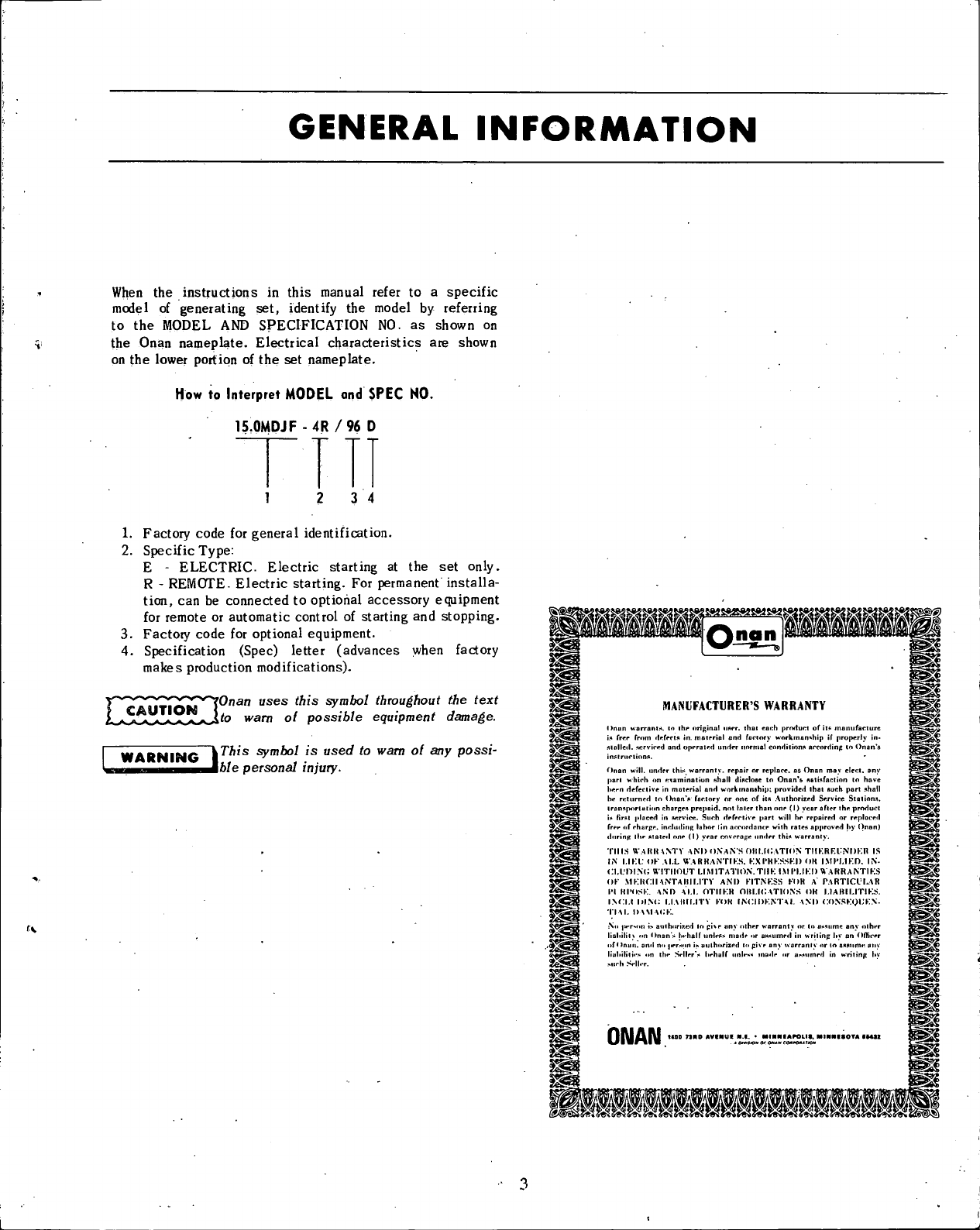
Onan MDJF Series Instruction Manual

OPERATORS
AND
ANUAL
FOR
Onan
ELECTRIC
GENERATING
SETS
MDJF
SEkiES
t
968-0345
6Abt3

TABLE
OF
CONTENTS
TITLEPAGE
GeneralInformation
3
Specifications
4
Dimensions
and
Clearances
5
AssemblyTorques
and
SpecialTools
7
Installation
8
Operation
. 17
Adjustments
21
GeneralMaintenance
24
RoutineCheckChart
26
MaintenanceSchedule
. . 27
TroubleshootingGuide
28
PartsCatalog
29
PERFORMANCE
CERTIFIED
We
certify
thatwhenproperlyinstalledand
operated
thisOnanelectricplant
will
deliverthe
full
powerandthe
voltageandfrequencyregulationpromisedbyits
nameplate
andpublishedspecifications.Thisplanthas
undergone
several
hours
ofrunning-inandtesting
under
realisticloadconditions,
in
accordance
with
procedures
certified
byanindependent
testinglaboratory.
ONAN 140073RDAVENUE
N.E.•
MINNEAPOLIS,MINNESOTA55432
*OIVISIOH Of ONAN CORPOI'llON
IMPORTANT!
RETURN
WARRANTY
CARD
ATTACHED
TO
UNIT.

INTRODUCTION
THISOPERATOR'S
MANUAL
CONTAINS
INFORMATION
PERTAINING
TOTHEINSTALLATION,OPERATION,ANDMAINTENANCEOFYOUR
ONAN
UNIT.
A PARTSCATALOGISALSOINCLUDEDINTHIS
MANUAL.
WESUGGESTTHATTHIS
MANUAL
ANDTHE
WIRING
DIAGRAM
WHICH
ACCOMPANIES
EVERY
ONAN
UNIT
BERETAINEDAND
REFERRED
TO
WHEN
MAKING
EQUIPMENTADJUSTMENTSORORDERINGPARTS.
ADDITIONALCOPIESAREAVAILABLEFORA
NOMINAL
CHARGE
FROMYOUR
ONAN
DISTRIBUTOR.
WHEN
ORDERINGPARTSREMEMBERTOINCLUDETHE
ONAN
MODEL,SPECIFICATION
LETTER,
ANDSERIALNUMBERLOCATED
ONTHENAMEPLATEOFYOUR
ONAN
UNIT.
THISISESSENTIALTO
ENSURE
THECORRECTPARTISSHIPPEDTOYOU.
FOR
MAJORREPAIR
SERVICE,
CONTACTYOUR
ONAN
AUTHORIZED
DISTRIBUTOR.

GENERAL
INFORMATION
When
theinsttuctionsinthismanualrefertoa specific
modelofgeneratingset,identifythemodelbyreferring
tothe
MODEL
AND
SPECIFICATION
NO.asshownon
the
Onan
nameplate.
Electrical
characteristicsareshown
onthelowerportionofthesetnameplate.
How
to
Interpret
MODEL
and
SPEC
NO.
15
OMDJ
F
- 4R/
96
D
1 3
4
1.Factory
code
forgeneralidentification.
2.
Specific
Type:
E
-
ELECTRIC.
Electric
startingatthesetonly.
R
-
REMOTE.
Electric
starting.Forpermanentinstalla-
tion,canbeconnectedtooptionalaccessoryequipment
forremoteorautomaticcontrolofstartingandstopping.
3.
Factory
code
foroptionalequipment.
4.Specification(Spec)letter(advanceswhenfactory
makesproductionmodifications).
CAUTION
'Onan uses this symbol throughout
the
text
to warn
ol
possible equipment damage.
WARNING
|^"ssym^'s
used
to
warn
ol any
possi-
H^HHMBBi^J&/e personal injury.
MANUFACTURER'S
WARRANTY
Onanwarrants.Inihe
nrigmal
iiAt-r.
thaitar.bproductofitnma
mi
fact
u
is
frrr
frnm
drfwlft
in.
motrriol
onH
fnrlory
workmanshipifproperlyin*
siollcil.
servicedandoperatedundernormalconditionsaccordingto
Onan's
inplrnrlinno.
Onan
will,
underthis
worrnnty.
repairnrreplace,asOnanmayelect,any
pan
which
onexamination
nhall
diocloaeto
Onan's
fintisfaction
lohove
hern
defeciiveinmaterialandworkmanship:providedlhatsuchpart
.ihall
hereturnedto
Onan's
factoryoroneofitsAuthorizedServiceSta
linns,
ironsporluiion
charges
prepaid,not
hiler
thanone
f
I)
yearaflertheproduci
if
first
placedin
wrvic*.
Suchdefectivepart
will
herepairedorreplaced
freeofcharpe,
including
lahor(in
accordance
wilh
rates
approvedhyOnon)
during
ihestatedone(1)yearcoverageunder
thin
warranly.
THIS
WARRANTY
AM)
ON.AN'S
OII
LIGATION
TMKRF.l'NDK.H
IS
IN
l.l
KL.'
OKALL
VIARK.ANTIK.S.
KX
I'H
KSSK.I)
OK
I.MPUKO.
IN-
<XUr>l.N(;
WITHOUT
LIMITATION.THK
IMIMJKI)
W.ARRANTIKS
OK
MKRCIIANTAIIIUTY
AND
K
ITN
KSS
KOHA
PARTICULAR
I'l
HI'O.SK.
ANOAM.
OTIIKH
OIII.I<;ATIONS
OR
I.1ABILITIKS.
I.NCI.I
IHN<;
LIAHILITY
KOK
INCIDKNTAI.
AND
CONSKQt'KN-
TIM.
DAM
ACK.
No
]MTMin
i>aulhoriiedlopi\eanyotherwarrantyorloa*<iumeany
olhei
lialiililt
on
Onan's
(..-half
unh-**
made
ora
KM
u
med'
in
wrilinp
hyan
fKhr.
of
*
Inuu.
amino
jiernon
ii>
uulhorizediopiveanvwarranlvoi
liuhililies
..niheSeller's
l.ehalf
unle«
made'ora^nmedin
writinp
hy
>urh
Sell.
r.
ONAN

SPECIFICATIONS
Nominal
dimensionsofgeneratingset(inches):
Height
2611/16
Width
205/16
Length
'.513/8:'
Weight
(approx.lb.)'. :.'..".....865
Numbercylinder(vertical
in-line)
4
Displacement(cubicinch)140
Cylinder
bore< , 31/2
Pistonstroke3 5/8
BHP
at1800rpm: 33.3
RPM
(for
60
hertz)
1800
RPM
(for50hertz)1500
Compressionratio19:1
Battery
voltage(ACset,exceptdualpurpose)*12
Batery
size
(ACset,exceptdualpurpose)
SAE
group
IH-two
in
series
• Yes
Amp
- hr,SAE20- hr(nominal)120
Battery
charge
rate
amperes
(normal)- AC
sets
2 to5
*Oil
capacityinU.S.
quarts
-
Refill
: .•6
Cooling
water
flow
(gallonsperminute). ' 6
Generatorcoolingair
(CFM
at1800rpm)136
Combustion
air
(CFM
at1800rpm): ^ '2
Total
cu.ft.permin.ofairrequired208
Diesel
fuel
lift
(maximumfeet).'6
•"
Maximum
recommendedpower
take-off
from
front
pulleyatanyload2 hp
Power
take-off
limit
atratedload'. 1 hp.
Injection
pump
(Am.
Boschtype)PSU
Output
isratedat
unity
powerfactorload
1-phase
Output
isratedat0.8powerfactor
3-phase
Rating
(outputinwatts)
AC,
50hertzset.,12,000
AC,
60hertzset, 15,M0
AC
voltageregulation
in
t
%
: ; 3
AC
frequencyregulationin
%
.•5
Revolving
field
type
generator
, Yes
120/240-
volt
single
phase
modelreconnectibleYes
Statictypeexciter(Magneciter): Yes
*
- Plus1/2quartfornew
filter.
•
. 24and32voltbatteriesoncertainmodifications.
NOTE:
Hertzisa
unit
offrequencyequaltoonecycleper
second.

DIMENSIONS
AND
CLEARANCES
Allclearancesgiven
at
roomtemperature
of
70°F.
Alldimensions
in
inchesunlessotherwisespecified.
MinimumMaximum
CAMSHAFT
Bearing
JournalDiameter,Front2.25002.2505
Bearing
Journal
Diameter,
Rear
1.1875
1.1880
Bearing
Clearance
Limit
0012.0037'
End
Play,Camshaft(inback
position)
007.039
Cam
Tappet
Hole
Diameter8755.8765
Cam
TappetDiameter8730.8725
CONNECTINGRODS
Large
BearingDiameter
(I.D.)
' 2.06152.0630
Small
BushingDiameter
(I.D.)
. . . 0.99030.9906
Clearance,LargeBearingtoCrankshaft' 001.0033
CYLINDER
Cylinder
Bore3-1/2
Cylinder
Diameter
Limits
3.49953.5005
CRANKSHAFT
Main
BearingJournalDiameter2.24272.2435
Crankshaft
Main
BearingClearance
(Original
Equipment)0030.0043
Connecting
RodJournalDiameter2.05972.0605
End
Play,Crankshaft010.015
PISTON(Measure
90°toPin)
Piston
Clearanceto
Cylinder
Wall
belowOil
Ring
Groove0055.0075
Piston
Pin
Hole
Diameter99005.99025
Ring
Groove
Width,
Top097.098
Ring
Groove
Width,
2nd. .0965.0975
Ring
Groove
Width,
3rd0965.0975
Ring
Groove
Width,
4th1895.1880
PISTON
PIN
Length
3.003
2.988
Diameter
9899.9901
Piston
ClearanceThumbPushFit
Connecting
RodBushingClearance0002.0007
PISTON
RINGS
Ring
Type
Top
Compression
2nd
Compression
3rd
OilScraper& Compression
RingWidth
Top
f 0925.0935
2nd
0925.0935
3vd
*":::09251 .0935

Minimum
Maximum
STARTING
MOTOR
Rotation
". . . . Counterclockwise
Pinion
Clearanceto
Pinion
Stop(SolenoidPlungerBottomed).070.120
Pinion
RestPosition
—
Distance
from
Pinion
Housing
Mounting
Face
to
OuterEdgeof
Pinion
1-9/32
1-15/32
Armature
EndPlay.005.030
TestSpecifications
No
Loadv.;10volts-
80
amps
5000
rpm
Min.
Stall
Torque4volts- 420
amps
7.8lbs.
ft.
Min.
Brush
SpringTension32-40
ounces
with
new
brushes
VALVE,
INTAKE
(Hardened
Chrome
Alloy)
StemDiameter.3405.3410
ClearanceinGuide'. . . . . . .0015.0030
Valve
Face
Seat
Angle
. . . 426
Valve
Clearance.017
VALVE,
EXHAUST
(Hardened
Chrome
Alloy)
StemDiameter3405.3415
ClearanceinGuide". . . .0030.0050
Valve
Face
Seat
Angle
45°
Valve
Clearance.017

ASSEMBLY
TORQUES
AND
SPECIAL
TOOLS
TORQUE
SPECIFICATIONS
FT.-LB.
Center
Main
Bolt
97-102
Connecting
Rod
Bolt
27-29
Cover-RockerBox8-10
Cylinder
Head
Bolt
44-46
Exhaust
Manifold
Nuts13-15•
Flywheel
Mounting
Screw65-70
Flywheel
HubNut17-21
Fuel
Pump
Mounting
Screws. 15-20
Gear
Case
Cover. 18-20
Glow
Plug10-15
Injection
Nozzle
Mounting
Screws20-21
Injection
Pump
Mounting
Screws15-16
Intake
Manifold
13-15
Oil
Base
Mounting
Screws45-50
Oil
Filter
Hand
Tight
+ 1/4to1/2
Turn
Oil
Pump
Mounting
Screws15-20
RearBearingPlate4045
Rocker
Arm
Nut4-10*
Rocker
Arm
Stud. ...35-40
Thru-Rotor-Stud
Nut55-60
*
- Thistorqueis
friction
betweenthe
threads
only
and
locks
thenutsinplace.Therockerarmnutsarefor
adjusting
valvelash.
CAUTION
Tighten nuts evenly
to
avoid manilold
damage.
Assembly
torques
assure
propertightness
without
dangerof
stripping
threads.Ifa torquewrenchisnotavailable,
estimatethe
degree
oftightness.Use
reasonable
forceand
awrenchofnormallength.
SpecialPlaceBoltsdonotrequirelockwashersor
gaskets.
Never
attempttousea lockwasher
with
these
bolts,it
will
defecttheirpurpose.Checkallstuds,nutsandscrews
often.
Tightenasneeded.
SPECIAL
TOOLSANDEQUIPMENT
These
toolsareavailable
from
Onantoaidserviceand
repair
work.
CrankshaftGear
Pulling
Ring
420-0275
Diesel
CompressionTester420-0283
Diesel
NozzleTester420-0184
Diesel
PintleNozzleCleaning
Tool
Set
(Includes
injection
nozzlecentering
tool)
. . . 420-0208
Driver,
FrontCamshaftBearing420-0252
Driver,
RearCamshaftBearing420-0251
Driver,
CenterCamshaftBearing420-0254
Driver,
Main
BearingFrontandRear420-0269
Driver,
Valve
Seat
420-0270
Oil
SealGuideand
Driver
RearFront420-0281
Ridge
Reamer420-0260
ReplacementBladefor420-0260420-0261
Valve
Seat
Remover420-0272
ReplacementBladesfor420-0272
4
20-0274

INSTALLATION
GENERAL
Proper
installation
is
very
important.
Consider
thefollowing
points:
adequate
generator
coolingair;
discharge
ofcircu-
lated
air;
adequate
fresh
inductionair;
adequate
engine
cooling
water;
discharge
of
circulated
water;
discharge
of
exhaust
gases;
electrical
connections;
fuel
connection;
sturdy
andflatfloor;and
accessible
for
operation
and
service.
Use
this
manual
asa
guide
to
help
withthe
installation;
refer
toTypical
Installation,
Figures
2 and3.
For
more
complete
instructions,
request
Onan
Technical
BulletinT-021.
Each
installation
must
be
considered
individuallyand
exe-
cuted
in
compliance
withall
regulations
whichmay
affect
the
installation.
The
advice
and
guidance
contained
inthe
booklet
entitled
Fire
Protection
Standard
(orMotor
Cralt:
(NFPANo.302)
offered
bythe
National
Fire
Protection
Association
International,
Boston
10,
Massachusetts,
will
behelpfultothe
installer
of
equipment
in
vessels.
CAPSCREW
LOCKWASHER
FLATWASHER
SNUBBER
"GENERATOROR
OILBASEMOUNT-
INGFOOT
CUSHION
MOUNTINGSPACER
BUSHING
'-DRIPPAN
FIGUREI.MOUNTINGCUSHION
LOCATION
Select
a
location
fortheunit,
preferably
near
the
vessels
main
keel,
whichisdry,
properly
ventilated,
above
low
lying
vapors
and
splash
fromthebilge.
Provide
accessibility
for
minor
servicing
operations,
draining
ofthe
crankcase,
lubricatingoilandthecooling
system.
MOUNTING
Thefloor
should
beflatand
give
support
directly
under
the
set
(Figure
1)
mounting
points.
Theunit
will
rock
onits
mounts.
A
2-1/2inch
clearance
around
theunitis
required
to
permit
rockingonits
mounts
without
restraint.
Use
adequately
flexible
exhaust
line,fuelline,
batteiy
cables,
and
elec-
trical
wires.
WATERLINE EXHAUSTHIGHWATERTEMP-
ERATURECUTOFFSWITCH
SUPPORT
MUFFLER
RUBBER
EXHAUST
HOSE
.^LOAD
<LWATER
LINE
VENTILATED
BATTERYBOX
FIGURE2.TYPICALINSTALLATION

Recommendedfluahtypethru-hull
fittingandwaterfilter.
TOGENERATORSET
SEACOCK
STRAINER
v— FLUSHTHRU-HULL
FITTING
WARNING:Donotusescooptypewaterinletfittings
ongeneratorsetsusingAqualiftmufflersystems
CAUTION Install Siphon Break Kit #155-0950 il
exhaust injection elbow is below load
wa'er line. Locate the Siphon Break at least 12inches
above load water line and in a vertical position. Remote
mounting the siphon break is permissible within a 5 loot
radius ol water injection exhaust elbow. Vertical position
and height ol valve must be maintained.
SIPHONBREAK•
(Seedetail)
-HANSERSTRAPS
Sf|VACUUMRELIEFVALVE
ADAPTER
/""ELBOW(2)
'RUBBERHOSE
WATEROUTLET
EXHAUSTWATER
INJECTIONELBOW
EXHAUSTOUTLET
TYPICAL
ABOVE
WATER
LINE
INSTALLATION
NOTE:
Makeprovisionforpassageofairbeneath
mufflertopreventcondensation..
TYPICAL
BELOW
WATER
LINE
INSTALLATION
FIGURE
3.
TYPICAL
INSTALLATION
Installtwo
hold-down
clamps
tothedrippan(frontand
rear
or
both
sides).
Secure
the
clamps
tothe
mounting
base.
For
maximum
noise
reduction
on
Onan
MDJF
units,
installthe
Onan
"Sound
Shield"
whichisan
insulated
fiberglass
enclosure
which
completely
surrounds'the
generating
set
(Figure
2).
Openings
are
provided
for
connection
toallex-
ternal
lines
and
wires.
Internal
air
ducts
reduce
air
borne
noise
toa minimum.
Contact
your
localONAN
dealer
for
noise
reduction
methods
andthe
special
kits
whichare
available.
shut-off
valve
atthe
tank.
When
thefuel
tank
is
shared
with
another
engine,
usea
separate
fuellineand
return
linefor
each
to
avoid
starving
the
plant.
(Figure
4)..
If
fuel
lift
must
exceed
6-feet,
installanauxiliary
electric
fuel
pump
atthefuel
supply.
FUEL
TANK
If
a
separate
fuel
tank
is
used,
installthe
tank
sothe
bottom
is
less
than
6^feet
below
thefuel
pump.
The
tank
top
must
be
below
fuel
pump
levelto
prevent
siphoning.
Installa
FUEL
CONNECTION
Connect the fuel line to the fuel pump inlet. Pump is threaded
7/16-24 NPTF (American Standard Internal Tapered Pipe
Thread). Important: Always use llexible tubing between en-
gine and the luel supply.

Thedieselenginerequiresa
fuel
supply
line
anda
separate
fuel
return
line.
Install
the
fuel
return
line
from
the7/T6-24
sizeopeninginthe
overflow
fitting
locatedonthe
injection
pump(wherethenozzle
fuel
return
line
isalsoconnected)to
thetopofthe
fuel
supplytank(Fig.5).
Do
notusegalvanizedlines,
fittings,
or
fuel
tanksinthe
fuel
system.Carefullycleanall
fuel
systemcomponents
beforeputtingtheplantintooperation.Any
dirt
orcontam-
ination
may
cause
major
damage
tothe
fuei
injection
system.
OIL
DRAIN
Theoildrainmaybeextendedtosuittheinstallation.The
oil
base
hasa 1/2"pipetappedhole.
^SHUT
FUEL
TANK
BELOW
FUEL
—
FUEL
PUMP
LEVEL
RETURN
LINE
PROPULSION
ENGINE
•
FUEL
RETURN
LINE
GENcKATOR'
FIGURE
4.
FUEL
LINE
ARRANGEMENT
VENTILATION
Thegeneratingsetrequiresfreshairforcombustionand
generator
cooling.
Onanrecommendsthattheventilation
systembeabletodeliver1-1/2to2 timestheairrequired
b;
theset.Whentheventilationsystem
depends
on
wind
or
boatmotion,usepowered
exhausters
toprovideventila-
tion
whentheboatisnotinmotion.Formore
information,
refertoOnanTechnical
Bulletin
T-021.
EXHAUST
WARNING
^Pfpe exhaust gases outside
of the
hull
I
-
exhaust gases
are
poisonous!
SeeInstallation,Figures2 and3.Theengineexhaust
connectionis
1-1/2"
pipetapped.
Install
a
separate
exhaust
line
as
follows:
1.
Abovevesselloadwater
line.
2.
Pitcheddownwardtopreventwaterbackflow.
3.Shield
line
near
combustiblematerial.
4.
Use
flexible
hose
ortubing.
5.Forturnsusesweeping
(long
radius)elbows.
6.
Increase
onepipesizeforevery10ft.inlength.
CONNECT
FUEL
RETURN
LINE
HERE
(Flexible
Line)
RETURN
LINE
Providea teeforwater
line
connectionforwetex-
haust
(Figure3)- refertoWaterDischarge
Line
Instructions.
Raise
thedryportionoftheexhaust
line
high
enoughtopreventwaterbackflowinginto
theengineunderallconditions.
Thewaterjacketedexhaust
manifold
ispipetapped
atboth
ends
forconvenienceinexhaust
line
conn-
ection.
FIGURE
5.
FUELSYSTEM
AQUALIFT
MUFFLER
(Optional)
The
Aqualift
isa
highly
efficient
marine
muffler
designedfor
aboveorbelowwater
line
installationswhenwatercooled
exhaust
systems
areused.
Because
ofinstallationvariables,
customersmustprovidethebrackets,
hoses
andclamps,re-
quired
forinstallation.
10

IMPORTANT: DO HOT USE SCOOP TYPE WATER INLET
FITTINGS when installing an Aqualilt mulller. Forward lacing
scoops develop sullicient ram pressure to lorce water past
the set's water pump, Hooding the exhaust system where it
may (low back, Hooding the engine cylinders. This can
happen only il the electric set is not running and boat is
underway.
1.
Secure
themufflertothe
predetermined
location
(within
ten-feet
ofthe
engine
exhaust
outlet)
using
"L"
brackets
(Figure
6)or
other
suitable
mounting
devices
such
aswood
blocks
or
metal
straps.
Flexible
mounts
maybe
used
ifso
desired.
Allow
forair
passage
under
mufflerto
prevent
condensation.
OUTLET
NOTTO
EXCEED
1INCH•
•L"
BRACKET
(MINIMUM
OF3)
<j£iLOCKWASHER
jg*-
NUTBASE
SHORTNIPPLE
DOUBLETAPPED
TANKBUSHING
LONG NIPPLE -p
,(INSIDEV .
MUFFLER)
r
SHORT
NIPPLE
REDUCERPIPE
BUSHING
NOTE:LONGNIPPLEGOESINSIDETANK
FIGURE6.SECURINGTHEMUFFLER
FIGURE7.AQUALIFTMUFFLER
3..
Connect
the
exhaust
linetothemuffler
outlet
andtothe
upper
elbow.
A
conventional
automobile
tail-pipe
hanger
bracket
maybe
used
to
hang
the
upper
elbow.
Rigid
pipe
maybe
used
in
place
offlexible
hose
for
certain
applica-
tions.
There
must
bea pitchof
one-half
inchperfoot
(i.e.,a
2-1/2"
drop
fora 5'run)inthe
exhaust
tubing
between
the
engine
exhaust
elbow
andthemufflerinlet.
Muffler
maybe
mounted
below
thelevelofthe
engine
if
necessary.
A minimum
drop
of
one-foot
is
necessary
be-
tween
the
engine
exhaust
outlet
onthehullto
prevent
water
from
washing
intothe
system
(seeFig.3).Anin-
crease
ofone
standard
pipe
size
for
every
ten
running
feet
of
exhaust
fromthemufflertothe
exhaust
outlet
is
necessary
to
prevent
excessive
backpressure.
pT^Cjrr^Donot
drill
holes
higher
than
oneinch
LA55-A-PAA^
X
above
the
extreme
lower
edge
ofthe
muffler
when
installing
mounts.
4.
Connect
the
exhaust
linefromthe
upper
elbow
totheex-
haust
outlet
onthe
hull.
The
exhaust
outlet
onthehull
must
be
positioned
so
that
a minimumot
water
will
enter-
whileat
anchor
or
under
way.
Important: Be sure all liftings are tight.
2.
Connect
the
exhaust
line(l1/2")tothe
marine
elbow
on
the
engine
andtothe
exhaust
inletonthemuffler.The
dis-
tance
fromthe
base
oftHemufflertothe
upper
elbow
on
the
exhaust
tubing
fromthemuffler
outlet
must
not
exceed
four-feet
(see
Figure
3). L^j^^^x^^^i interior
the lile expectancy;
on the mulller will damage the
protective coating decreasing
11

WIRE
SIZE
DISTANCE
#18 to
65ft.
#16 to
100ft.
#14 to
150
ft.
#12 to
280ft.
FORWARD
SLEEPINGQUARTERS
PILOT'S
STATION
GENERATOR
MOMENTARYCONTACT
SWITCH
(Onan
No.
308-0155
or
equal)
FRONT
DRAINBLOCKHERE PRIMING
PLUG
7REMOVEPUMPCOVER
TODRAIN
RUBBERHOSE
(LINEFROMWATER
SOURCE)
1/2"I.D.
OR LARGER
~~
LOOSENLINE
TODRAIN
EXHAUST
MANIFOLD
DRAIN
HERE
STARTING
MOTOR
BATTERY
NEGATIVE:
6VOLT
BATTERIES
«»
FIGURE
8.
FILL
AND
DRAINLOCATIONS 12
FIGURE
9.
REMOTECONTROLSAND
BATTERY
CONNECTIONS

BATTERY
CONNECTION
Battery
requiresnegativeground.Donotattemptto
change
batteiy
polarity
on
these
sets.
Refertoset
wiring
diagram.
CAUTION
11
the
battery
is
connected
to the
charging
circuit with
the
wrong polarity, damage
will occur alter three minutes while stopped
or in
live
seconds while running. Alternator windings will
be
damag-
ed almost instantly
il
battery charging circuit
is
shorted
belore
the
resistor.
Refertosetnameplateforbatteryvoltage.ForAC
plants
with
12
volt
system,providetwo6
volt
batteries
connectedin
series
(onebattery'snegativetotheother
battery'spositive,Figure9)for105amp-hr,12
volt
source.
For
ACplants
with
32
volt
system,provide32
volt
setof
batteriesand200amperefused
switch,
see
wiring
diagram
for
connections.
Connectthebatterypositive(+)tothestarterengaging
solenoid
terminalpost.Connectthefcattery
nega-
tive
(-)
toa goodgroundontheengine.(Figure9).
WATER
SUPPLY
LINE
(FIGURE
8)
A
continuoussupplyof
cooling
waterisrequired.The
waterpump
inlet
is1/4"pipethreadto1/2"
hose
coupling.
Usea sectionof
flexible
hose
near
thesettoabsorb
vibrations.
Theinsidediameteroftheplumbingmustbe
1/2"orlarger.Usepermatexorotherpipe
sealer
onall
pipe
fittings
insupply
line
topump.
Normally,
thepump
should
deliver6 gallonsof
cooling
waterperminute.
Measurethedischargedwater
flow
afterthermostatopens,
to
assure
thesupply
line
islargeenough.Reduceresistance
on
piperunslongerthan5-ft.byusinglargerinsidedia-
meter
plumbing.
Toprovesuction
line
isair
tight,
seethat
nobubbles
appear
indischargedwater.Anairleak
reduces
lubrication
andshortens
life
ofpumpsimpeller.
Install
a
strainerinthewatersuction
line
inlet
andwhereaccessible
for
cleaning.
REMOTE
START
-
STOP
SWITCH
(OPTIONAL)
For
remote
control
startingandstopping,use3 wiresto
connecttheremote
switch
(SPDT,momentarycontact,center-
off
type)totheterminalblockmarkedB+,1,2,3,inthe
set
control
boxusing
wire
sizes
as
listed
inFigure9.Pre-
heat
circuit
requiresanextra
wire
toterminalH and
momentarycontact
switch
(SPST)connection.Remove
jumper
betweenterminals3 andH before
installing
remote
wiring.
LOAD
WIRE
CONNECTIONS
(AC)
Thesetnameplateshowstheelectricaloutputratingofthe
setinwatts,voltsandhertz.Theset
wiring
diagramshows
theelectricalcircuitsandconnections
necessary
forthe
for
theavailableoutputvoltage.
Also
seeFigure12.
Meet
allapplicableelectricalcoderequirements.
Work
should
bedonebya
qualified
servicemanorelectrician
because
theinstallation
will
beinspectedandapproved.
Theset
control
box
(junction
box)hasknockoutsections
to
accommodateloadwires.Use
flexible
conduitand
strandedloadwires
near
thesettoabsorb
vibration.
Use
sufficiently
largeinsulatedwires.Stripinsulation
from
wire
ends
as
necessary
forcleanconnections.Connect
eachload
wire
tothepropergeneratoroutput,leadinside
theset
control
box.Insulate
bare
ends
ofungrounded
wires.
Usea
bolt
(throughthe
control
box)toconnect
thegrounded(-i-)generatorleadandload
wire.
Install
afusedmain
switch
(or
circuit
breaker)betweenthegen-
erating
setandload(Figure11).Ifa testrunindicates
wrong
rotationof3
phase
motorsintheload
circuit,
switch
theconnectionsatanytwogeneratorterminals.
Balance
.
All
Loads:Cunentforanyoneoutputloadmust
not
exceednameplate
rating.
Overloadingcan
damage
thegeneratorwindings.
Divide
theloadsequallybetween
output
leads.
Single
Phase
Loads
on
Three
Phase
Generators:
Any
combination
ofsingle
phase
andthree
phase
loadingcan
beusedatthe
same
timeas
long
asthecurrentforany
oneoutputlead
does
notexceedthegeneratornameplate
rating.
TOLOAD
GENERATOR
120-V.
FUSE
OR
CIRCUIT
BREAKER
GROUNDED
CURRENT
CARRYING
CONDUCTOR
UNGROUNDED
CURRENT
CARRYING
CONDUCTOR
THESE
LINES
FROM
^
DOCKSIDE
POWER
SOURCE
FIGURE
II.
DOCKSIDE
POWERSOURCE
13

Output
LeadMarkings:GeneratorsaremarkedTl,T2,etc.
These
identifying
marksalso
appear
onthe
wiring
diagram.
Voltage
SelectiononReconnectibleSingle
Phase
Genera-
tors:
These
modelsarereconnectibleforuseasa 120/240
volt
3
wire;
a 120
volt
2
wire
or240volt2
wire
powersource
(Figure
12).
Load
Connections:Refertothe
figure
which
illustrates
theloadconnectionsfortheoutputshownonyour
set's
nameplate.
CAUTION Do
not use
existing neoprene impeller
water pump
lor hot
water side
ol
cooling
system. Heat
or
soluble
oil (in
many rust inhibitors
and
anti-lreezes) will damage
the
impeller. Always connect
the neoprene impeller pump
to the
cold water side.
Use
acentrifugal metal impeller water pump (Onan #132-0110
or equal)
in the hot
water side. Drive
it
with
a
belt from
the set's power take-oll.
Spec
A throughC:Useanexpansiontankinthehotwater
side.
Delta
Generator:GeneratorleadToisthegeneratorcenter
tapbetweenTlandT2.TheToleadisnormallynot
groundedbutcanbegroundedifrequired(Figure
12-B).
Single
phase
poweratcentertappedlegavailableupto
2/3of
full
ratedthree
phase
power.
Discharged
water
leaves
at
heat
exchangerandthento
exhaustsystemwater
inlet.
Supply
line
connectionsare
the
same
asstandardsystem(Figure13).Refertothe
instructions
forwatersupply
line
inthissection.
Fill
closed
cooling
systems
with
clean,alkali-freewater,
to
theproper
level.
Addanapprovedrust
inhibitor
tothe
coolant.
Ifthecoolantisanti-freeze,testitperiodically.
HEAT
EXCHANGER
COOLING
(Optional).
This
isa closed
cooling
systemcommonlyreferredtoas
fresh
water
cooling.
Watercirculatedthroughtheengineis
termed
fresh. water,hotwater,jacketedwater,etc.Water
circulated
throughthe
heat
exchanger
only
iscalledraw
water,seawater,
cold
water,dischargedwater,etc.This
system
(with
anti-freezecoolant)isrecommendedwhere
freezing
hazards
existorwheretheownerwantstoprevent
saltwaterproblems.
Two
conditions
prevail:
(1)Factoiyinstalled
heat
exchanger,
and(2)CustomerinstalledOnan
heat
exchangerkit.Get
details
from
Onan.
Install
a newzinc
"pencil"
(Figure13)
which
screws
into
fresh
wateroutletendof
heat
exchanger,everytwomonths
or
asinspectiondictates.
l^^y^QlJ^jj
Use
high temperature cut-oil switch
in
overheating.
1
the hot
water side
to
protect unit Irom
14

UNGROUNDEDLOAD
WIRE(BLACK) -Q
Tl-T3oe
120
V.
(JOIN)
o
<Q
ae<
GROUNDEDLOAD
j-^
WIRE
(WHITE)_JC~""^
T2-
T4
LU
O
UNGROUNDEDLOAD
WIRE(BLACK)
T
OT..T4.?<
2s
]
GROUNDEDLOAD
.WIRE(WHITE)
(JOIN)
T2
—(JOIN
AND
GROUND)
UNGROUNDEDLOADWIRE(BLACK) o
120
V.
240
V.—J
120
V.
GROUNDEDLOADWIRE(WHITE)
UNGROUNDEDLOADWIRE(BLACK)
IPhase,ReconnectibleGenerator
(60hertz1model
has
code
-3C
gives
2
wire
or3
wireservice)
o
Tl
O
t-
u>
2
<Q
-
«<
O
"JUi
-i
Z—'
ui
T4
O
3
PHASE
NAMEPLATE
(HIGHER
x
VOLTAGE)
UNGROUNDEDLOADWIRE(BLACK)
UNGROUNDEDLOADWIRE(BLACK) o
k^UNGROUNDEDLOADWIRE(BLACK)^
rn
u
AAA
j
,
rGROUNDEDLOADWIRE(WHITE)
A= N ameplatelowervoltage,!phasecireuit
B
=
Namepiate
highervoltage
,1
phasecircuit
(60hertz
120/208
voltmodelhascode
-4)
Y—Connected
2
Tl
4/1
Q
<
O
T3
<
oe
LU
TO
5
3
PHASE
NAMEPLATE
(HIGHER
VOLTAGE)
NEUTRAL
LOADWIRENORMALLYUNGROUNDED
^
T
T TOISTHE
GENERATOR
S
CENTER
TAPOT0
A
A
BETWEEN
TlANDT2
UNGROUNDEDLOADWIRE(BLACK)
A
=N a
m
epl
at
e lowervo
11
age,l
p
h as
e
circuit
B
=
Nameplate
higher
voltage,1
phasecircuit
DeltaConnected(60hertz120/240voltmodel
has
code
-5D)
SINGLE
PHASE
POWERAT
CENTER
TAPPED
LEG
AVAILABLE
UPTO2/3OF
FULL
RATED
THREE
PHASE
POWER
to
Q
<
On
-OT2
•O73
O
•—
<
ee
Ui
Z
Ui
o
FIGURE
12.
WIRINGCONNECTIONS
15

OUTLET-
RAWWATER
TO
EXHAUSTLINE
REARCYLINDER
BLOCKCONNECTION
,ENGINEDRIVEN
WATERPUMP
(RAWWATER)
RAWCOOLINGWATER
FROMSOURCE
SPECIFICATION
A THROUGHC
FRONTCYLINDER
BLOCKCONNECTION
CENTRIFUGALPUMP
(FRESHWATER)
RAWWATER
^FRESHWATERINCLOSEDSYSTEM
THERMOSTAT
HOUSIN FILL -BLEEDERVALVE
WATERMANIFOLD HEAT
EXCHANGER
ENGINEDRIVEN
WATERPUMP
(RAWWATER)
RAWWATER
DISCHARGE
REARCYLINDER
BLOCKCONNECTION
—•—•-—--~RAWWATER
""FRONTCYLINDER
BLOCKCONNECTION'WWFRESHWATERINCLOSEDSYSTEM
INLET- RAWWATER
CENTRIFUGALPUMP
(FRESHWATER)
BEGINSPECIFICATION
D -HEATEXCHANGER•
BRACKET
FIGURE
13.
HEATEXCHANGER
PLUMBING
16

OPERATION
CRANKCASE
OIL
Useanoil
with
theAPIdesignationCD/SE,orCD/SD
(formerly
DS)thathas
passed
the
Series
3 Testandat
least
Sequences
IIAandHIAoftheAutomotiveManu-
facturer'sMS
Sequence
Tests.(DMoil
which
has
passed
theAutomotiveManufacturer'sMS
Sequence
Tests
andthe
MIL-L-2104B
Tests
mayalsobeusedwhenambienttempera-
turesarelowerthan
30°F.)
Toreduceoilconsumption
to
a normal
level
intheshortesttimeona neworrebuilt
"J"
series
dieselengine,useCC
(formerly
DM)oil
(pass-
ing
theMS
Sequence
Tests)forthe
first
fill
only
(50to100
hours),then
change
totherecommendedoil.
TEMPERATURE
Above
32
0F
0oFto320F
Below
0oF
GRADE
SAE
30
SAE
.10W-30,5W-20,or
10W,
5W-30
SAE
5W-20or5W-30
Do
notmix
brands
or
grades.
RefertoMaintenanceSection
for
recommendedoil
changes.
RECOMMENDED
FUEL
Dependsonoperatingconcfitions.UseNO.2 diesel
fuel
for
best
economy.UseNO.1 diesel
fuel
(a)whenambienttem-
peratureisbelow320F.,or(b)atalltemperaturesduring
long
periodsof
light
engineload,(c)ifpreferredby
user.
Uselowsulfurcontent
fuel
havinga pourpoint
(ability
to
filter)
ofat
least
10OF-belowthelowestexpectedtempera-
ture.
.
Keep
fuel
cleanandprotected
from
adverse
weather.
Leave
some
roomforexpansionwhen
filling
thetank.
INITIAL
START
Checktheenginetomake
sure
ithas
been
filled
with
oil
andthat
fuel
systemisair-free.
Bleed
air
from
fuel
systemas
follows:
Disconnectthe
fuel
WORK
TRANSFER
PUMP
PRIMING
LEVER
UNTIL
FUEL
FLOWS
FROM
RE-
TURN
LINE
FITTING
OF
INJECTION
PUMP.
return
line.
SeeFig.14.Operatethehand
priming
leveron
diaphragmtype
fuel,
transferpump
until
therearenoairbub-
blesin
fuel
flowing
from
the
fuel
return
line
fitting.
Then
connectthe
fuel
return
line.
NOTE:
Ifthecamshaftpump
lobeisup,crankengineonerevolutiontopermithand
prim-
ing.
Whenfinished,return
priming
lever
inward
(disengaged
position)
topermitnormalpumpoperation.
Temporarily
removetheplug
from
thewaterpump
inlet
fitting.
Figure
10.
Fill
thepump
with
watertolubricateandprime
it.
Replaceplugbeforeoperation.
STARTING
(1)
For
cold
enginestartingabove550F,
depress
themani-
fold
heater
switchforoneminute.(2)PushSTART-STOP
switch
toitsSTARTposition.(3)
Release
switchafteren-
gine
starts
and
reaches
speed.
(4)Oil
pressure
shouldread
at
least
20psi(pressure-reliefvalveisnotadjustable).
Themostcommonfailuretostartis
caused
by
unit
running
out
offuel—andthennotproperlybleedingthe
fuel
system
beforeattemptingtostart.
If
thesetcontrolhasa
re-set
button,pushitto
re-set
after
a shutdownresulting
from
lowoil
pressure
or
high
water
temperatureoccurs.
Find
the
cause
beforere-startingthe
engine.Ifcontinuousfalsestartingoccurs,make
sure
the
centrifugal
switch(Fig.16)
closes
during
speed
build-up.
Theadjustableresistorslidetap(inthecharging
circuit)
is
settogiveapproximatelya
2-ampere
chargingrate.For
applicationsrequiringfrequentstarts,checkbatteryspecific
gravity
periodicallyand,if
necessary,
increase
thecharging
rate
slightly
(moveslidetap
nearer
ungroundedlead)
until
it
keeps
thebatterycharged.Adjust
only
whensetis
stopped.
Avoid
overcharging.Theresistorislocatedin
thegeneratorairoutlet.
If
a
separate
automaticdemandcontrolforstartingandstop-
ping
isused,adjustthecharge
rate
foritsmaximum4.5
amperes.
Thisnormally
keeps
batterychargedevenifstarts-
occurasoftenas15-minutesapart.
Extremesinstartingtemperaturesmayrequireadditional
preheating.Ifengine
fails
tostart
quickly,
rest
engine
several
seconds
and
repeat
starting
sequence
applying
preheat
fora longer
interval.
r^^TI^rXkr^'?
^ notWPhovervoltagetothestarting
CAUTION
J .
FIGURE
14.
BLEEDING
THE
FUEL
SYSTEM
Idrear
t at any
time. Overvoltage will
destroy
the
glow, plugs
and air
heater
in two to
three
17

FIGURE
IS.
OPERATING
CYCLE
seconds.
II it
becomes necessary
to use an
additional
source
ol
power
to
start
the
unit
— use a
12volt battery
connected
in
parallel.
AUTOMATIC
STARTING
AND
STOPPING
Separate
controlsmaybeusedforautomaticstartandstop,
but
mustprovideenginepre-heating.
The
automatic
control
hasa timedelayrelaytopre-heat
glow
plugsandthe
manifold
heaterforabout20-seconds
beforecrankingoccurs.Removethejumperintheunit's
control
box
which
connects
terminal
H (heater)to
terminal
3
("start
circuit')
andconnectseparate-controlpre-heat
circuit
to
thesetH
terminal
when
installing
the
control.
Thetime
18
delay
relayalsodelaysengagementofthestarterwhenload
is
re-appliedbeforetheenginestopscompletely.
STOPPING
(1)
Pushstart-stop
switch
tostop
position.
(2)
Release
switch
when
unit
stops.Ifstop
circuit
fails,
close
fuel
valve.
APPLYING
LOAD
If
practicable,
allow
setto
warm
upbeforeconnectinga
heavyload.Continuousgeneratoroverloadingmay
cause
high
operating
temperaturesthatcandamagethe
windings.
The
generatorcansafelyhandleanoverloadtemporarily,butfor
normal
operation,keeptheload
within
nameplate
rating.
The
exhaustsystemmay
form
carbondeposits
during
operationat

light
loads.
Apply
full
loadoccasionallybeforeshut-downto
preventexcessivecarbonaccumulations.
Try
toconnecttheloadin
steps
insteadof
full
loadat
onetime.Mostinstallationsusea
line
switchthatmustbe
closedtoconnecta portionoftheload.
EXERCISE
STANDBY
SETS
Infrequent
setuseresultsinhardsetting.Operatestandby
seta
least
30minutes
each
week.Runlongerifbattery
needs
charging.
BREAK-IN
PROCEDURE
The
unit
shouldberuninthe
following
sequence:
1.
One
half
hourat1/2load.
2.
One
half
hourat3/4load.
3.FulHoad.
Continuousmnningunderone
half
loadduringthe
first
few
hundredhoursusuallyresultsinpoorpiston
ring
:
seating,causinghigherthannormaloilconsumptionand
blowby.
NOTE: Drain
the
initial
oil
alter 50hours
ol
operation
while
the
engine
is
still
hot.
SAFETY
DEVICES
In
case
ofdangerously
high
coolant(water)temperatureor
low
oil
pressure,
the
cut-off
switch
stops
the
unit.
After
an
emergencystop,investigateandcorrectthe
cause.
Press
re-set
buttonbeforerestarting.
EMERGENCY
OPERATION
IF
BATTERY
FAILS
MDJF
generating
sets
requirea batteryforrunning.Ifthe
setbattery
fails
completelyandsetmustbeoperatedduring
anemergency,a batterycanbeshared
with
etherequipment
provided
thesetcharging
circuit
isdisconnectedas
follows:
Removetheammeter
wire
connectedtoterminalNo.8 inthe
control
boxand
tape
the
bare
end.Theset
will
notcharge
thebattery
with
thislead
wire
disconnected.
HEAT
EXCHANGER
(OPTIONAL)
FILLING
Improper
filling
ofthe
heat
exchangercan
cause
overheating
of
theengine.Therefore,topreventthispossibility,
follow
these
instructionswheneveraddingcoolingtothe
heat
exchanger:
1.
Remove
fill
cap.
2.
Open
fill
ventvalve
(turn
counterclockwise).
3.Removevent
plug.
(Spec
A throughC).
4.
Fill
with
coolant.
5.Close
fill
ventvalve
(turn
clockwise).
6.Replacevent
plug.
(Spec
AthroughC).
7.Replace
fill
cap.
8.Operate
unit
.10minutesat
full
load,watchforleaks.
9.Shutdown
unit.
Alter running unit
10
minutes,
the
closed cooling system
is
pressurized
and
hot.
Open
the 14 lb.
pressure
cap
slowly
to
vent
pressure.
10.
Slowly
open
pressure
capandcheckwater
level.
11.
Fill
systemtotop
with
coolant.
OUT-OF-SERVICE
PROTECTION
When
taking
unit
outofservicefor30-daysorlonger,proper
storage
methodsmustbeusedtoprevent
damage
from
cor-
rosion,
contamination,andtemperatureextremes.
Fuel
System
1.
Cleanaircleaner(if
used)
- donotserviceaircleaner
with
oil.
Checkandcleanairintake.
2.
Coveror
seal
exposedairintakeopenings.
3.Cleanthrottlelinkage(andgovernorlinkage)thoroughly.
Lubricate
metal
ball
joints
with
light
machineoil(do
not
lubricateplastic
ball
joints).
Oil
System
1.
Drain
enginelubricatingoil
while
engineiswarm.Serv-
icetheengine
with
properoil.TAGtheengineto
IDENTIFY
thelubricatingoilinstalled.
Secure
theoil
filter
cap.
2.
Rempve
fuel
injectors.Pour2
ounces
ofrust
inhibitor
oil
(SAE50substitute)into
each
cylinder.Crankengine
overbyhandseveralrevolutionstolubricatecylinder
walls,
pistons,andrings.
Install
injectors.
3.Removeandserviceoil
filter.
Cooling
System
1.
Drain
entirecoolingsystem
including
watercooledex-
haust
manifold
andexhaust
line.
Drain
heat
exchanger
or
keelcoolercomponents,enginecylinderblock,and
waterpumps.
Generatingunitsequipped
with
heat
exchangerorkeel
cooling
maybe
filled
with
a goodqualityanti-freezeif
freezing
temperaturesareexpected.
Drain
only
those
componentsnotprotected
from
freezing(exhaustlines,
waterintakeandoutletlines,etc.).
19
Other manuals for MDJF Series
1
Table of contents
Other Onan Inverter manuals

Onan
Onan Genset LK Series User manual

Onan
Onan DFE Series User manual

Onan
Onan 6GO-F User manual

Onan
Onan 16004 Series User manual

Onan
Onan BGM Series User manual

Onan
Onan NH Instruction Manual

Onan
Onan DYC Series Instruction Manual

Onan
Onan 3.0 kW AJ GEN SET User manual

Onan
Onan DYG Series Instruction Manual

Onan
Onan NH User manual