Onan DFE Series User manual

Onon
Installation
Manual
OF
Diesel
Driven
960-0601
6-88
PrintedinU.SA

SafetyPrecautions
V,
Beforeoperatingthegeneratorset,readtheOperator'sMan-
ualandbecomefamiliarwithitandtheequipment.Safeand
efficientoperationcanbeachievedonlyiftheequipmentis
properlyoperatedandmaintained.Manyaccidentsare
causedbyfailuretofollowfundamentalrulesandprecautions.
Thefollowingsymbols,foundthroughoutthismanual,alert
youtopotentiallydangerousconditionstotheoperator,ser-
vicepersonnel,ortheequipment.
This symbol warns of immediate
hazards which will result in severe
personal injury or death.
A
DANGER
AWARNING
severe personal injury or death.
This symbol refers to a hazard or
unsafe practice which can result in
ACAUTION This symbol refers to a hazard or
unsafe practice which can result in
personal injury or product or property damage.
FUEL
AND
FUMES
ARE
FLAMMABLE.
Fire
andexplosion
can
result
from
improper
practices.
•DONOTfillfueltankswhileengineisrunning,unless
tanksareoutsidetheenginecompartment.Fuelcontact
withhotengineorexhaustisa potentialfirehazard.
•DONOTpermitanyflame,cigarette,pilotlight,spark,or
otherignitionsourcenearthegeneratorsetorfueltank.
•Fuellinesmustbeadequatelysecuredandfreeofleaks.
Fuelconnectionattheengineshouldbemadewithan
approvedflexibleline.Donotusecopperpipingon
flexi-
blelinesascopperwillbecomebrittleifcontinuously
vibratedorrepeatedlybent
•Besureallfuelsupplieshavea positiveshutoffvalve.
•Donotsmokewhileservicingleadacidbatteries.Lead
acidbatteriesemita highlyexplosivehydrogengasthat
canbeignitedbyelectricalarcingorbysmoking.
EXHAUST
GASES
ARE
DEADLY
•Provideanadequateexhaustsystemtoproperlyexpel
discharged
gases.
Visuallyandaudiblyinspecttheexhaust
dailyforleaksperthemaintenanceschedule.Ensurethat
exhaustmanifoldsaresecureandnot
warped.
Donotuse
exhaustgasestoheata compartment.
•Besurethe°unitiswellventilated.
MOVING
PARTS
CAN
CAUSE
SEVERE
PERSONAL
INJURY
OR
DEATH
•Keepyourhands,clothing,andjewelryawayfrommoving
parts.
•Beforestartingworkonthegeneratorset,disconnect
startingbatteries,negative(-)cablefirst.Thiswillprevent
accidentalstarting.
•Makesurethatfastenersonthegeneratorsetaresecure.
Tightensupportsandclamps,keepguardsinposition
overfans,drivebelts,etc.
•Donotwearlooseclothingorjewelryinthevicinityof
movingparts,orwhileworkingonelectricalequipment.
Looseclothingandjewelrycanbecomecaughtinmoving
parts.
Jewelrycanshortoutelectricalcontactsandcause
shockorburning.
•Ifadjustmentmustbemadewhiletheunitisrunning,use
extremecautionaroundhotmanifolds,movingparts,etc.
ELECTRICAL
SHOCK
CAN
CAUSE
SEVERE
PERSONAL
INJURY
OR
DEATH
•Removeelectricpowerbeforeremovingprotectiveshields
ortouchingelectricalequipment.Userubberinsulative
matsplacedondrywoodplatformsoverfloorsthatare
metalorconcretewhenaroundelectricalequipment.Do
notweardampclothing(particularlywetshoes)orallow
skinsurfacetobedampwhenhandlingelectrical
equipment.
•Useextremecautionwhenworkingonelectricalcompo-
nents.
Highvoltagescancauseinjuryordeath.DONOT
tamperwithinterlocks.
•Followallapplicablestateandlocalelectricalcodes.
Haveallelectricalinstallationsperformedbya qualified
licensedelectrician.Tagopenswitchestoavoidacciden-
talclosure.
•DONOTCONNECTGENERATORSETDIRECTLYTO
ANYBUILDINGELECTRICALSYSTEM.Hazardous
vol-
tagescanflowfromthegeneratorsetintotheutilityline.
Thiscreatesa potentialforelectrocutionorproperty
damage.Connectonlythroughanapprovedisolation
switchoranapprovedparallelingdevice.
GENERAL
SAFETY
PRECAUTIONS
•Coolantsunderpressurehavea higherboilingpointthan
water.DONOTopena radiatororheatexchangerpres-
surecapwhiletheengineisrunning.Allowthegenerator
settocoolandbleedthesystempressurefirst.
•Provideappropriatefireextinguishersandinstallthemin
convenientlocations.Consultthelocalfiredepartmentfor
thecorrecttypeofextinguishertouse.Donotusefoamon
•>electricalfires.UseextinguishersratedABCbyNFPA.
•Makesurethatragsarenotleftonorneartheengine.
•Removeallunnecessarygreaseandoilfromtheunit.
Accumulatedgreaseandoilcancauseoverheatingand
enginedamagewhichpresenta potentialfirehazard.
•Keepthegeneratorsetandthesurroundingareaclean
andfreefromobstructions.Removeanydebrisfromthe
setandkeepthefloorcleananddry.
•Donotworkonthisequipmentwhenmentallyorphysi-
cally
fatigued,
orafterconsuminganyalcoholordrugthat
makestheoperationofequipmentunsafe.
LS-8
TableofContents
SAFETYPRECAUTIONSInsideFrontCover
INTRODUCTION2
AboutthisManual2
InstallationOverview2
SPECIFICATIONS
3
MOUNTINGTHEGENERATORSET5
General5
Location5
Mounting5
AccesstoSet5
MECHANICALCONNECTIONS6
FuelSystem6
ExhaustSystem7
VentilationSystem8
CoolingSystem8
ELECTRICALCONNECTIONS11
General• 11
TransferSwitch11
ACWiring11
DCWiring14
PRESTARTPREPARATIONS16
Coolant16
Lubrication16
Fuel17
Ventilation17
Exhaust17
Electrical17
Mechanical-.17
INITIALSTARTCHECKS18
Starting18
EngineGauges18
ACMeters(IfEquipped)18
EngineMonitorIndicatorLamps18
GeneratorVoltageChecks18
GeneratorFrequency19
ExhaustSystem21
FuelSystem• 21
DCElectricalSystem21
CoolingSystem21
MechanicalAdjustments21

Introduction
ABOUT
THIS
MANUAL
ThismanualprovidesinstallationinstructionsfortheOF
Seriesgeneratorsets.Thisincludesthefollowing
information:
•Mounting— Recommendationsforfasteninggener-
atorsettobaseandspacerequirementsfornormal
operationandservice.
•MechanicalConnections— Locationofconnection
pointsfor
fuel,
exhaust,ventilation,andcooling.
•ElectricalConnections— Locationofelectrical
con-
nectionpointsforthecontrol,generator,andstarting
system.
. . .
•Prestart— Checklistofitemsorproceduresneeded
topreparegeneratorsetforoperation.
•InitialStartup— Testcompletesystemloensure
properinstallation,satisfactoryperformance,and
safeoperation.iRefertoQperatorsManualfor
trou-
bleshootingJ;nfor;mation.
ThismanualDOESNOTprovideapplicationinforma-
tion for selectingageneratorsetm designingthecom-
pleteinstallation.Ifitisnecessarytodesignthevarious
integratedsystems(fuel,exhaust,cooling,
etc.),
review
standardinstallationpractices,orspecifysystemmate-
rials,
additionahinformation
isrequired.
Forengineerinjg
dataspecifictothe.generatorset,refertoiheOFSeries
specificationandproductdatasheets.Forgenerator
applicationinformationabout^generatorsetinstallation,
refertothefollowingOnanTechnicalBulletins.
T-009/T-017— SelectingOnanGeneratorSets
T-030— InstallationInformationfor
Liquid-CooledGenSets
BulletinT-030isa particularlyusefulinstallationrefer-
enceandisshippedwiththismanual.Bulletin
T-009/T-017isincludedintheOnanPowerSystems
Manualormaybeobtainedseparatelyonrequestfrom
anauthorizedOnandistributoj'.
INSTALLATION
OVERVIEW
Theseinstallationrecommendationsapplytotypical
generatorsetinstallationswithstandardmodelgenera-
torsets.Wheneverpossible,theserecommendations
alsocoverfactorydesignedoptionsormodifications.
However,becauseofthemanyvariablesinanyinstalla-
tion,
itisnotpossibletoprovidespecificrecommenda-
tionsforeverysituation.Ifthereareanyouestionsnot
answeredbythismanual,contactanOnandistributor
forassistance.
ApplicationandInstallation
Astandbypowersystemmustbecarefullyplannedand
correctlyinstalledtoensureproperoperation.This
involvestwoessentialelements:applicationandinstallation.
•Application(asitappliestogeneratorsetinstallations)
referstothedesignofthecompletestandbypower
systemthatusuallyincludespowerdistributionequip-
ment,transferswitches,ventilationequipment,mount-
ingpads,andcooling,exhaust,andfuelsystems.Each
componentmustbecorrectlydesignedsothecomplete
systemwillfunctionas
intended.
Applicationanddesign
isanengineeringfunctiongenerallydonebyspecifying
engineers.orothertrained,specialists.Specifying
engi-
neersareresponsibleforthedesignofthecomplete
standbysystemandforselectingthematerialsandpro-
•
ductsrequired.
Installationreferstotheactualset-upandassemblyof
thestandbypowersystem.Theinstallersset-upand
connectthevariouscomponentsofthesystemasspeci-
fiedinthesystemdesignplan.Thecomplexityofthe
standbysystemnormallyrequiresthespecialskillsof
qualifiedelectricians,plumbers,sheetmetalworkers,
etc.tocompletethevarioussegmentsoftheinstallation.
Thisisnecessarytoensureallcomponentsare
assembledusingstandardmethodsandpractices.
Fig-
ure1 showsa typicalinstailationandTable
1
liststhe
equipmentinstallationspecifications.
Safety
Considerations
Thegeneratorsethasbeemcarefullydesignedtopro^
videsafeandefficientservice.However,theoverall
safetyandreliabilityofthecompletesystemisdepend-
entonmanyfactorsoutsidethecontrolofthegenerator
setmanufacturer.Toavoidpossiblesafetyhazards,
makeallmechanicalandelectricalconnectionstothe
generatorsetexactlyasspecifiedinthismanual.All
systemsexternaltothegenerator
(fuel,
exhaust,electri-
cal,
etc.)mustcomplywithallapplicablecodes.Make
certainallrequiredinspectionsandtestshavebeen
completedandallcoderequirementshavebeensatis-
fiedbeforecertifyingtheinstallationiscompleteand
readyforservice.

Specifications
TABLE
1.
EQUIPMENT
INSTALLATION
SPECIFICATIONS
SYSTEMS
175
DFE
FuelSystem
InletFittingSize
ReturnFittingSize
FuelPump
(LiftingCapacity
7/8-14
UNF-2A
3/4-16
djNF-2A
5feet(i:525m)
Exhaust
System
ExhaustConnection
(in.
pipethread)
ExhaustBackpressure
(MaximumAllowable)
5inchesNPT
41inchesH2O
3inchesHg
ElectricalSystem
StartingVoltage
Battery 24VoltsDC
Two,
12-VoltGroup8D
AWARNING
INCORRECT INSTALLATION, SERVICE OR REPLACEMENT OF PARTS CAN
RESULTIN
SEVERE
PERSONALINJURY AND EQUIPMENT DAMAGE. SERVICE
PERSONNELMUST BE QUALIFIED
TO
PERFORM ELECTRICAL AND MECHAN-
ICAL COMPONENT INSTALLATION.

THIMBLE
SWEEPINGELBOW
»DUCT
35*
COOLINGAIRINLETMUSTBE
ATLEAST1-1/2TIMESLARGER
THANRADIATORDUCTOUTLET
AREAONRADIATORCOOLED
MODELS.
FLOWOFCOOLINGAIR'AND
HEATEDAIRMAYBE
CON-
TROLLEDBYAUTOMATICALLY
OPERATEDLOUVERS.
RGURE
1.
TYPICAL
DFE
INSTALLATION,

Mounting
theGeneratorSet
GENERAL
Mostgeneratorsetinstallationsmustbeengineeredto
ensurethegeneratorsetwillfunctionproperlyunderthe
expectedloadconditions.Usetheseinstructionsasa
generalguideonly.Followtheinstructionsof^the
con-
sultingengineerwhenlocatingorinstallingany;compo-
nents.
Thecompleteinstallationmustcomplywithall
localandstatebuildingcodes,fireordinances,and
otherapplicableregulations.RefertoOnanTechnical
Bulletin,
T-030,forfurtherinstallationinformation.
Requirementstobeconsideredpriortoinstallation:
•Levelmountingsurface
•Adequatecoolingair
•Adequatefreshinductionair
•Dischargeofcirculatedair
•Dischargeofexhaustgases
•Electricalconnections
•Accessibilityforoperationandservicing
•Noiselevels
•Vibrationisolation
LOCATION
Generatorsetlocationisdecidedmainlybyrelatedsys-
temssuchasventilation,wiring,
fuel,
andexhaust.The
setshouldbelocatedasnearaspossibletothemain
powerfusebox.
Providea locationawayfromextremeambienttempera-
turesandprotectthegeneratorsetfromadverse
weatherconditions.Anoptionalhousingisavailablefor
outsideoperation.
Use
3/4-inch
diameter,anchoredmountingboltsto
securethegeneratorsetskidtothefloortoprevent
movement.Securetheskidusinga flatwasherand
hexagonnutforeachbolt(seeFigure2).
HEXNUT
FLATWASHER
•12
IN.
305mm)
MOUNTING
BOLT
FIGURE2.BOLTDIAGRAM
MOUNTING
Generatorsetsaremountedonasteelskidthatprovides
propersupport.Theengine-generatorassemblyisiso-
latedfromtheskidframebyrubbermountsthatprovide
adequatevibrationisolationfornormalinstallations.For
criticalinstallations,installvibrationisolatorsbetween
theskidbaseandfoundations.
Mountthegeneratorsetona substantialandlevelbase
suchasaconcrete
pad.
Forproperspacingofmounting
boltsandsetmountingdimensions,seespecificgenera-
torsetspecificationsheet.
ACCESS
TOSET
Planforaccesstothegeneratorsetforservicingand
provideadequatelightingaroundtheunit.Forconven-
ienceingeneralservicingsuchastheradiator,fanbelt,
andchangingthecrankcaseoil;thesurfaceofthe
mountingbaseshouldbeatleast6 inches(152mm)
abovethefloor.

Mechanical
Connections
Thegenerator
set
mechanical:systeminstaUation
includesconnectingthe
fuel,
exhaust,ventilationand
coolingsystems.Beforestartinganytypeof
fuel
installa-
tion,
Onanrecommendsaliipertinentstateandlocal
codes
be
compliedwithand:theinstallationmust
be
inspectedbeforetheunitisput
in,
service.
-
FUEL
SYSTEM
Cumminsenginesusedonthe
DF
seriesgeneratorsets
normallyuseASTMNo.
2
Diesel
fuel.
They
will,
how-
ever,operateorvdceselfuelswithinthespeeificattons
delineated
in
the.
Cumminsenginemanual.
General
In
all
fuelsystemtnstaiFattons,cfeantrness
isot
the
utmostimportance;.Makeevetyeffort
to
preventen-
trance*ofmoisture,,dirt
or
contaminants
of
any
kind.
Cleanallfuelsystemcomponentsbeforeinstalling.
Useonlycompatibfe.metaftuetlinestoavofdelectroly-
siswhenfuel
lines;
mustbeburiedLNeverusegafwart.-
ized
or
copper
fuel;
tinesorfittingswtthdieseffuelas
it
tendstoflakeo.ffandeortfaminatethe
fuel.
Useaflexibte
section
of
tubing;between,theengineand
fuel:
supply
linetowithstand.vibration.
ACAUTIOt*
Never use galvanized or copper fuel
lines,,
fittings oriuettanks witftdiesel
fuel
systems.
Condensation in the tank and lines com-
bines with the sulfur in diesel fuel toproduce suffuric
acid. The molecufar structure of the copper or galvan-
ized lines
or
tanks reacts with
the,
acid and contami-
nates the fuel.
Anelectricsolenoidshutoftvatveinthesupplyline
is
alwaysdesirabfeand!requtred!forindoorautomatic,or
remotestartmginstalfettors.Connect
the
sotenotd
'-wires
to
thebattefyigpitionictreuit
to
openthevalve
duringgeneratorsetoperation.
Supply
Tank
Locatethefueltankascloseaspossibletothegenera-
torsetand
within;
theSfoot
(1.5
metre}liftcapacityofthe
fuelpump
if
possiibfe.Choose
a
tankthathassufficient
capacitytokeepthegeneratormnning.continuouslyat
fullloadfor
at
least36hours.
AWARNING
Fuel
teaks
create
fire
andexplosion
hazards
whichcanresult
in
severe:
personal
injuryordeath.
Always
use
flexible
tubing
betweenengineandthe
fuel
supply
toavoidlinefailure
and
leaks
duetovibration.The
fuel
system
must
meet
applicable
codes.
Atypicalundergroundfuelsystemconsists
ofa
main
fueltank,ventandfillpipes,fuelsupplyline,andfuel
returnline(seeFigure
1).
Ifthetankisinstalledbelowthe
liftcapabilitiesofthestandardfueltransferpump,a day
tankandauxiliarypumpwillalso
be
required.
If
an*
overheadtankis
installed,
a daytankandfloatvalvewill
berequired
to
preventfuelheadpressuresfrombeing
placedonthefuelsystemcomponents.RefertoTechni-
calBulletinT-030forexamples
of
fuelsupplysystems
thatrequire
a
daytank.
DayTank
(If
Used)
Daytanksarefueltransfertankswhicharousedwhen
thestandardenginefuelpumpdoesnothavethecapac-
itytodrawthefuel
from:
thesupplytank;orthesupply
tank
is
overheadandpresentsproblems
of
highfuel
headpressureforthefuelreturn.SeeFigure
3.
FUELPUMPRETURNLINE
(jFUSED);
INJECTOR,
FUELRETURN-
LINE
Aliimodelsrequirefuehreturn-line!
frominjectorstotank.
.fl-
FLOATTYPE.SWITCH
CONNECTTO
ACOUTPUT
'
" V
VENTLINE
/
'DAY'TANK
25GAL.(20LITRE)
MINIMUMCAPACITY
FUELTRANSFER
PUMP
-
ELECTRIC
MOTORDRIVEN
LARGER
OVERFLOW
UNE
SUPPLY/
LINE FILL
PIPE
ll
11
li
11
II
11
UNDERGROUND
It
11
1
•
FUEL
TANK
11
u
ES-1214-1
FIGURE
3.
DAYTANK
(TYPICAL)

SupplyTankLowerThanEngine:Withthisinstallation,
thedaytankisinstallednearthegeneratorsetand
withintheenginefuelpumpliftcapability,butbelowthe
fuelinjectionsystem.Installanauxiliaryfuelpumpas
closeaspossibletothesupplytanktopumpfuelfrom
thesupplytanktothedaytank.A floatswitchintheday
tankcontrolsoperationoftheauxiliaryfuelpump.
Thesupplytanktopmustbebelowthedaytanktoptoprevent
siphoningfromthefuelsupplytanktothedaytank.
Providea returnlinefromtheengineinjectionsystem
returnconnectiontothedaytank(nearthe
top).
Provide
adaytankoverflowlinetothesupplytankincasethe
floatswitchfailstoshutoffthefueltransferpump.
AWARNING Spilled fuel presents the hazard of
fire or explosion which can result in
severe personal injury or death. Provide an overflow
line to the
supply
tank from the day tank.
SupplyTankHigherThanEngine:Installthedaytank
nearthegeneratorsetandwithintheenginefuelpump
liftcapability,butbelowthefuelinjectionsystem.Use
fuellineatleastaslargeasthefuelpumpinlet.The
enginefuelreturnlinemust-enterthedaytank.
Includea shutoffsolenoidinthefuellinebetweenthe
fuelsupplytankandthedaytank.Itstopsfuelflowwhen
thegeneratorsetisoff.
RAINCAP
DRIPCAP
HOLESINENDOF
INNERSLEEVE
ROOF
9INCHMINIMUM
(230mm).
9INCHMINIMUM
(230mm)
(230mm)(230mm)
9INCHMIN, tt 9 INCHMIN
WALLORPARTITION
,1)1^/-
HOLESIN
V
END
OF
INNERSLEEVE
DiameterolThimbleMustBe12Inches(305mm)
LargerThanDiameterofExhaustPipe EXS-1036
Engine
Fuel
Connections
Identificationtagsareattachedtothefuelsupplyline
andfuelreturnlineconnectionsbythefactory.Flexible
linesforconnectingbetweentheengineandthesta-
tionaryfuellinearesuppliedasstandardequipment.
RefertoTable1,SPECIFICATIONStorthefittingsizes.
EXHAUST
SYSTEM
Pipeexhaustgasestotheoutsideofanyenclosure.
Locatetheexhaustoutletawayfromairinletstoavoid
exhaustgasesfromre-enteringtheenclosure.Exhaust
installationsaresubjecttovariousdetrimentalcondi-
tionssuchasextremeheat,infrequentoperation,and
lightloads.Regularlyinspecttheexhaustsystemboth
visuallyandaudiblytoensuretheentiresystemremains
fumetightandsafeforoperation.
AWARNING Inhalation of exhaust gases can
result in severe personal injury or
death. Useextreme care during installation
to
ensure a
tight exhaust
system.
Useanapprovedthimble(Figure4)whereexhaust
pipespassthroughwallorpartitions.Refertothe
NationalFireProtectionAssociationBulletin,Volume4,
section211coveringStandardsforChimneys,Firepla-
cesandVentsforsuggestedcoderequirements.Build
accordingtothecoderequirementsineffectatthe
installationsite.
FIGURE4.EXHAUSTTHIMBLE(TYPICAL)
AWARNING Inhalation of exhaust gases can
result in severe personal injury or
death. Do not use exhaust heat to warm a room, com-
partment, or storage area.
Onanhasraincapsavailableforthedischargeendof
verticalexhaustpipes.Theraincapclampsontotheend
ofthepipeandopensduetoexhaustdischargeforce
fromthegeneratorset.Whenthegeneratorsetis
stopped,
theraincapautomaticallycloses,protecting
theexhaustsystemfrom
rain,
snow,etc.
ACAUTION Weight applied to the engine mani-
fold can result in manifold damage.
Support
the
mufflerand exhaustpiping
so
no weight
or
stress is applied to the engine exhaust manifold.
Avoidsharpbendsbyusingsweeping,longradius
elbowsandprovideadequatesupportformufflers,and
tailpipe.Pitcha horizontalrunofexhaustpipe
DOWNWARDtoallowanymoisturecondensationto
drainawayfromtheengine.Ifanexhaustpipemustbe
turnedupward,installa condensationtrapatthepoint
wheretherisebegins(seeFigure5).

IFEXHAUSTLINEMUSTBEPITCHEDUPWARD.
CONSTRUCT
A
TRAPOFPIPEFITTINGSAT
POINTOFRISE
AVOID
SHARP
BENDS
DRAINCONDENSATIONTRAP
PERIODICALLY
EXS-1046
FIGURES.EXHAUSTCONDENSATIONTRAP(TYPICAL)
Shield.orinsulateexhaustlines
if
there
isa
danger
of
personalcontact.Allow
at
least
12
inches(305mm)
of
clearance
if
thepipespasscloseto
a
combustiblewall
orpartition.
VENTILATION
SYSTEM
Generatorsetscreateconsiderableheatthatmust
be
removed
by
properventilation.Outdoorinstallations
rely
on
natural
air
circulation
but
indoorinstallations
needproperlysized
and
positionedvents
forthe
requiredairflow.Refer
to
OnanTechnicalBulletin,
T-030,
for
additionalapplicationinformation.
Vents
and
Ducts
Forindoorinstallations,locatevents
so
incoming
air
passesthrough
the
immediatearea
of
theinstallation
beforeexhausting.Installthe
air
outlethigherthan
the
airinlet
to
allow
for
convection
air
movement(see
Fig-
ure1
fora
typicalinstallation).
Size
the
vents
and
ducts
so
they
are
largeenough
to
allow
the
requiredflowrate
ofair.The
"freearea"
of
ductsmust
beas
large
asthe
exposedarea
ofthe
radiator.RefertotheDFEseriesProductDataSheetsfor
theairflowrequirements.
Windwillrestrictfreeairflow
ifit
blowsdirectlyintothe
airoutletvent.Locate
the
outletvent
sothe
effects
of
windareeliminated.
Foroperationoutsidea building,
a
shelterhousingwith
electricallyoperatedlouvres
is
available
asan
option.
Transformersconnectedacross
the
generatoroutput
supplycurrent
to
themotors.
When
the
generator
is
operating,current
inthe
trans-
formersactuatethemotorsandopen
the
louvres.
The
louvresareheldopenfortheduration
of
thesetopera-
tion,
then
are
closed
by
returnspringswhen
thesetis
shutdown.
Dampers
Dampers
are
used
inany
system
to
block
the
airflow
throughtheventswhenthegeneratorsetisnotrunning.
This
is
sometimesnecessary
in
coldclimates
to
keep
thegeneratorenclosure
ata
normaltemperature.
RadiatorSet
Radiatorsetcooling
air
isdrawnpasttherearoftheset
byafanwhichblowsairthroughtheradiator.Locatethe
airinlet
to
therear
of
setandnearthefloor.Make
the
inletventopening
1
-1
/2
timeslargerthantheradiator.
Locatethecoolingairoutletdirectlyinfrontoftheradia-
torandascloseaspossible.Theeffectiveopeningarea
shouldbe1.3timesaslargeastheradiator
area.
Length
andshape
of
the
air
outletductshouldofferminimum
restriction
to
airflow.
Usea
duct
of
sheetmetal
and
canvasbetweentheradiatorandthe
air
outletopening
topreventrecirculation
of
heated
airand
provide
for
flexibleconnection.
^
HeatExchanger
*
Heatexchangercooledsetsdonotuse
a
conventional
radiator.Instead,
a
constantlychangingwaterflow
coolstheheatexchangerwhichinturncoolstheengine
coolant.Sufficient
air
movementandfresh
air
must
be
available
to
disperseheat
radiated
from
theheatexchanger.
Toprovidesufficientairflow,ventilationfans
maybe
required.
Sizethefanstoremoveallheatrejectedtothe
roombythegenerator
set,
exhaustpipesandotherheat
producingequipment.Maintaining
a
temperature
dif-
ferential
of20°to
30°F
(11°to170C)is
usually
satisfactory.
COOLING
SYSTEMS
A
set
mountedradiatorwithenginedrivenfan
is
stan-
dard
onthe
generator
set.
Optionalcoolingsystems
includeremoteradiatorcooling
and
heatexchanger
cooling.
Thefollowingsectionsbrieflycover
the
installation
requirements
for
eachsystem.Refer
to
Technical
Bul-
letinT-030
for
moredetailedinformation.
Standard
RadiatorCooling
Thestandardradiatorcoolingsystem
(see
Figure
1)
uses
a set
mountedradiatorwith
an
enginedriven
pushertypefan
to
coolthegeneratorset.
Airis
pulled
fromthegeneratorendofthesetacrosstheengineand
thenforcedthrough
the
radiator.
Anair
ductadapter
flangesurroundstheradiatorgrill
to
allowmounting
of
the
air
dischargeduct.Refer
to
thesection
on
Ventila-
tion
for
locationandsizing
of
ductsandvents.

RemoteRadiator(Optional)
Remoteradiatorscanbelocateda horizontalora
verti-
caldistance,fromanengine.Thehorizontaldistanceis
limitedbythecapabilityoftheenginedrivenwaterpump
andthemaximumexternalFrictionHeadpressure.The
verticaldistanceislimitedtothemaximumStaticHead
pressurewhichcanbeimposedoncoolantsystem
gasketsandsealswithoutleakageofcoolantfromcoo-
lantsystemcomponents.TheFrictionandStaticHead
pressuresofeachGenSetareincludedintheirProduct
DataSheet.
Thetwokeydesignconsiderationsina remoteradiator
installationaretheverticaldistance(X)fromtheengine
centerlinetotheradiatortopandthehorizontaldistance
(Y)
fromtheenginefronttotheradiatorcenterline(see
Figure6).Thesedistancesdetermineifanyadditional
equipmentisrequiredsuchasa surgetank,auxiliary
pump,
orhot
well.
Becauseofthemanydesignconsid-
erations,allremoteradiatorinstallationsmustbe
engi-
neeredtoinsurethatthesystemwillfunctionproperly.
Followtheinstructionsoftheconsultingengineerwhen
installinga remoteradiatorsystem-Additionalinforma-
tioniscontainedinTechnicalBulletinT-030.
Thissystemcanreducesetenclosureairflowrequire-
mentsandnoiselevels.Properoperationdependsona
constantsupplyofrawwaterforheatremoval.Adjust
theflowtomaintainwatertemperaturebetween165°
and1950F(74°and910C)whileviewingthewater
temperaturegauge.Theenginecoolantsideofthesys-
temcanbeprotectedfromfreezing;therawwaterside
cannotbeprotected.
Allheatexchangercooledsetsmustbeconnectedtoa
pressurizedsupplyofcoldwater.Makeconnectionsto
thesetwithflexiblepipetoabsorbvibration.Onthecool
waterline,installa solenoidvalvetoshutofftheflow
whenthesetisshutdownanda rateofflowvalveto
controlenginetemperature.Thisvalvecanbeeither
manualorautomatic.Actualrateofflowwilldependon
inletwatertemperature.
Adjustthevalvetomaintainwatertemperaturebetween
165°to195°F (74°to910C)whileoperatingtheunitat
full
load.
Heat
Exchanger
(Optional)
Thiscoolingsystemusesa shellandtubetypeheat
exchangerinsteadofthestandardradiatorandfan(see
Figure7).Enginejacketcoolantcirculatesthroughthe
shellsideoftheheatexchanger,whilethecoolingwater
ispumpedthroughthetubes.Enginecoolantandraw
waterdonotmix.Thistypeofcoolingseparationis
necessarywhentherawwatercontainsscaleforming
lime,
orotherimpurities.
7PSIMINIMUM(48kPa)PRESSURECAP
FILLER
Beforefillingcoolingsystem,checkallhardwarefor
tightness.Thisincludeshoseclamps,capscrews,fit-
tingsandconnections.Useflexiblecoolantlineswith
heatexchangerorremotemountedradiator.
C
ENGINE
GENERATORSET
m
FIGURE6.REMOTERADIATORINSTALLATION
9
CS-1130

EXPANSIONTANK
DRAIN
'WATER
•IN;
MANUALORAUTOMATIC
WATER.TEMP-CONTROL.
VALVE STRAINER^ CS-1075
FIGURE
7.
TYPICAL
HEAT
EXCHANGER
Coolant
Filter
One
spin-ontypexorrosion
filter
(Figure8)isstandard
equipment.
This
precharge
filter
is
compatible
with
plain
waterandallethyleneglycol
base
permanentanti-
freeze
coolants.
Refertoengine manufacturer'smanual
forinstructionslfamethoxypropanal
base
anti-freeze
is
desired.
Replace>filterperiodicallyas
recommended;
in
MAINTENANCE
section
ofOperatorsManual.
COOLANTFILTER-
SHUT-OFFVALVE
SPIN-ON
COOLANTFILTER-
SHUT-OFF1VALVE
BATTERYCHARGING
ALTERNATOR
FIGURE
8.
TYPICAL
COOLANT
FILTER;
Coolant
Heater
(Optional)
A
coolantheateris
used
tokeepenginecoolant
warm
whentheengine
is
shut
down.
It
heats
and
circulates
the
coolant
within
theengine.
This
reduces
start-up
time
and
lessens
engine wear
caused
bycold
starts.
Itis
electrically
operatedandthermostaticallycontrolled.
ACAUTION The heater must not be operated
while the cooling system is empty
or
whentheengineisrunning
or,
damage
to theheater-will
occur.
Figure9 showsthetheheaterlineconnections.Con-
nectthe.heatertoa sourceofpowerthatwillbeon
duringthetimetheengineisnotrunning.Besurethe
voltageratingiscorrectfortheheaterelementrating.-
WATERHEATER
OUTLET
OILPLUG -- WATER
HEATER
INLET
ELEMENT
HEADAND
VALVEASSY
DRAINCOCK
FIGURE
9.
TYPICAL
COOLANT
HEATER
10

Electrical
Connections
GENERAL
Thegeneratorsetelectricalsysteminstallationincludes.
connectingthe
load,
installingthecontrolwiring,and
connectingthebatteries.Thebatteriesshouldbe
con-
nectedlasttoavoidaccidentalstartingoftheunitduring
installation.
Mostlocalregulationsrequirewiringconnectionsbe-
rnade bya licensedelectricianandtheinstallationmust
beinspectedandapprovedbeforeoperation.All
con-
nections,wiresizes,etc.mustconformtotherequire-
mentsofallelectricalcodesineffectattheinstallation
site.
AWARNING Improper wiring can result in fire and
severe personal injury or death.
TRANSFER
SWITCH
Iftheinstallationisforstandbyservice,atransferswitch
isrequiredforswitchingtheloadfromthenormalpower
sourcetothegeneratorset(seeFigure10).Eithera
manualorautomatictransferswitchmaybeused.
Fol-
lowtheinstallationinstructionsprovidedwiththe
transferswitchwhenconnectingtheloadandcontrol
wiring.
Onansuppliedtransferswitchesmatchthe
generatorrating.
AC
WIRING
GeneratorVoltage
Connections
Thegeneratoroutputvoltagesandmaximumcurrent
ratingisspecifiedonthegeneratornameplate.Line-to-
neutralvoltageisalwaysthelowervoltageshownonthe
nameplateandline-to-linevoltageisthehigherrating.
Generatorscanbedividedintotwogroups,reconnecti-
bleandnon-reconnectible.Thereconnectibletype
generatorcanbewiredtogiveoneofseveralpossible
voltages.Non-reconnectibletypegeneratorsproduce
onlyonespecificvoltageandcannotbewiredtogivea
differentvoltagewithoutextensivemodifications.The
followingsectionsexplaintheconnectionprocedurefor
eachvoltagecode.
Non-ReconnectibleGenerators(VoltageCodes6D,
7R,and9X):Thesegeneratorsarewiredatthefactory
fora specificvoltageandarenotintendedforreconnec-
tion.
Thevoltageandcorrespondingcurrentrating
(amperes)areshownonthenameplate.
ReconnectibleGenerators(VoltageCodes15and
515):
Generatorswithcodes15(for 60Hertz)and515
(for50Hertz)arethreephasegeneratorsthatcanbe
reconnectedforanyofthevoltagesshowninFigure
11.
Refertothesetnameplateforthecorrespondingcurrent
rating(amperes).
LOAD
NORMAL
SOURCE GENSET
FIGURE10.LOADTRANSFERSWITCH
(TYPICALFUNCTION)
Load
Connections
The12leadgeneratorswithloadconnectionwiresARE
NOTconnectedtogetherintheoutputboxwhen
shippedfromthefactory.These12wiresarelabeledT1
throughT12andmustbebroughttogetherbeforemak-
ingloadconnections.Proceedasfollows:
1.
Removetherightorleftpanelfromoutputbox..
2.
Bolttheloadwirestotheappropriategeneratorlead
wiresintheoutputboxaccordingtoFigure11for
requiredvoltage.
3.Insulatetheconnections.
11

220/380VOLT,
3
PHASE,
60
HERTZ
347/600VOLT,
3
PHASE,
60
HERTZ
if-/ GENERATOR
CONNECTION.
SCHEMATIC
DIAGRAM*
GENERATORCONNECTIONWIRINGDIAGRAM
(WITHCURRENTTRANSFORMERSWHENUSED)
15;
120/240•'
US/230
1TO/220
6.0.
\3:B/.T»B.
:ii5 ll!S/2:3:0
f X
1.T0/Z20
: IT.
soe
so;
12.0/20.8
uyiAo.
sis:
1:10/1.9
0.
115/20.0
nq/ios:
UT/220
6.0
60:
e>S>:
[iXK
SO:
SO
'so;
t3r TV
TIO'T6T717.Til
T-41T81
T3T12TS
to.
11
C.T21
13
CT22
CT24
CT23'
TS
TIO.'TI2
T3
T9
24o/*l,6.
254/440
2Z7/48.0
SIS
22X^3801
230/4Ott
2:40/4«l,6.
•2
S-4/4.4
0
6.0;
60;
6.0;
SO
50;
SO;
SO
1.a,
11
\.
CT21
CT22
C
T24
TIO;T
li
TT
2:TT.T7T4iTT.
TS*
T5T3,
9aC2l93.
FIGURE
11.
GENERATORVOLTAGECONNEG.TIONS
12

WheninstallingsetswiththeoptionalACammeter,the
generatoroutputleadsmustberoutedthrougha current
transformerforpropermeteroperation(SeeFigure12).
Thetransformersareidentified
CT21,
CT22,andCT23
(threephaseonly)onthewiringdiagramandelectrical
schematics.RefertoFigure11toidentifytheoutput
leadsthatmustberoutedthrougheachtransformer.
Usea cabletietosecuretheloosetransformertothe
generatoroutputleads.
CURRENTTRANSFORMERS
FIGURE12.CURRENTTRANSFORMERS
Load
Balancing
Whenconnectingloadstothegeneratorset,balance
theloadssothecurrentflowfromeachlineterminal
(L1,
L2,
andL3)isaboutthesame.Thisisespeciallyimpor-
tantifbothsinglephase-andthreephaseloadsare
connected.
Anycombinationofsinglephaseandthree
phaseloadingcanbeusedaslongaseachlinecurrent
isaboutthesame,within10percentofmedianvalue,
andnolinecurrentexceedsthenameplateratingofthe
generator.Checkthecurrentflowfromeachlineafter
connectionsbyobservingthecontrolpanelammeter.
Grounding
Groundinginvolvesmakinga conductingconnection
betweenthemetalpartsofthegeneratorsetoroneofits
electricalcircuitsandthe
earth.
Thedesignandinstalla-
tionofa groundingsystemisaffectedbymanyfactors
suchastheuseofmultipletransformers,groundfault
protectionrequirements,andphysicallocationofthe
generator.Followtherecommendationsoftheconsult-
ingengineerwheninstallingthegroundingsystem.
AWARNING Confacf with electrical equipment
can result in severe personal injury
or death. It is extremely important that bonding and
equipment grounding be properly done. All metallic
parts that could become energized under abnormal
conditions must be properly grounded.
ControlHeater(Optional)
Acontrolheaterprovidesameansofhumidity/tempera-
turecontrolofthecontrolboxinteriortoprotectthe
componentsandensuretheireffectivenesswhenthe
generatorsetissubjectedtovaryingambientaircondi-
tionsduringextendedperiodsofnon-use(seeFigure
13).
Theelementiscontrolledbyanadjustable
thermostat.
ES-1563-3
FIGURE13.CONTROLHEATER
13

DCWIRING
RemoteControlConnections
.Provisionsaremadeinsidethecontrolboxfbraddition
-ofoptionalremote.startlng^awdaf
amjs.
Gonnectionsare
madeontheterminalbJook
<TB1)
locatedontheengine
monitoroireuitboard{A-l
1|.
Connect
oneor
more
'•remoteswitchesacrossremoteterminalandS*/termi-
nal(SeeFigure14).
Ifthedistancebetweenvihegeneratorsetaiadremote
sstationsHSless;than?1©©01eet^305mm),use1i8gauge
strandedcopperwirei^the^^distocefe1©0Gtb^OO0feet
(305
to610
m);
use.>
1$gaugestrandedoopperwire.
••«lkViimys:
mfumritft&cSSto^v&finQfa^separ^chmdyift;
"ffomitheAG^powe^s<»b*es
lo
avoid:
aindacing
c\jiTenfe
^h"atrc0uldiCause5pTia>i©(nswftlwh^ecmj*©!;
RemoteMonitorConnections
Provisionsaremadeinsidethecontrolboxforaddition
ofoptionalremotemonitoring
on
thesegeneratorsets
employingoptionalDetector12Control(12lightpanel).
Connections
are
made
onthe
terminalblock
(TB2)
locatedontheenginemonitorcircuit.board(A11).
ACAUTION Do Not install DC control wiring in the
same conduit
as the AC
power.'AC
voltage induced,currents can create operational prob-
lems with electronic solid-state devices.
•.
i:
S^OCPOWER)
TB2
1 FAULT
2 -
INPUT
1
NON-TIMED
2-
EAULT
2 •
OUTPUT
i
..SHUTDOWN
;:3-
•
FAULT.1
-
INPUT
\
TIMED
-
4 FAULT
1
-
OUTPUT
i
SHUTDOWN
5 LAMPTEST/RESET
6 OVERCRANK
7 OVERSPEED
8
•
HIGHENGINETEMPERATURE
.9
:
LOWOILPRESSURE
10 PRE-KIGHENGINETEMPERiATUIBE
11 PRE«WOILPRESSURE
12 SWITCHOFF
13 LOWENGINETEMPERATURE
14 LOWFUEL
-
INPUT
15 LOWFUEL
-
OUTPUT
16 •SHUT-OOWN
ENGINE
CONTROL
•MONITOR
•All
XES-1S61
FfSURE14.REMOTECONTROLANDREMOTEMONITORCONNECTIONS
14

Battery
Connections
Startingtheunitrequires24-voltbatterycurrent.Use
two12-volt(seeSPECIFICATIONS)batteriesfora nor-
malinstallation.Connectthebatteriesinseries(nega-
tivepostoffirstbatterytopositivepostofsecond)as
showninFigure15.Normalinstallationbatterycables
areincluded.Increasethecablesizeifbatteriesare
locatedremotelyfromgeneratorset.Servicethebatter-
iesasnecessary.Infrequentunituse(asinemergency
standbyservice)mayallowthebatteriestoself-
dischargetothepointwheretheycannotstarttheunit.If
installinganautomatictransferswitchthathasnobuilt-
inchargecircuit,connecta specialfloatcharger.
Ignition of explosive battery gases
can cause severe personal injury. Do
STARTINGMOTOR
SOLENOID BATTERYPOSITIVE
CONNECTION
AWARNING
not smoke while servicing batteries.
CONNECTNEGATIVECABLETO
CONVENIENTBOLTONENGINE
THECONNECTIONMUSTBECLEAN
ANDPAINTFREE
2-12VOLTBATTERIES
FIGURE15.BATTERYCONNECTIONS
15

Beforeattempting theira^itia'ls'tafting^tteseieneFator^,
be?
sureitisservicediatselfre'adyffOT*oiDerationJFillSftre
coolant;
I
u
brication:and;fu^lfs^teTns:aTid;pwm^^
riGation-andfuelsystfems.- '
mmmm
Enginecoolantisdriii^^tor^^ipwerttlB^teFre^ta'ft-
i
ng,
fi
11
thecoolantsystem^withlthie-reGOmmended
codl-
antpertheOpera\m^Mmiia\MMN^NMN'G'£s$ee\\m,
Coolantinstructions:
LUBRICATION
EnginelubricationJissdrained•priorttorshipment.SBefore
starting,
fillandprimeStheHubricatiO^
follows:
1.
Remove-oil
M'nlet^litfiBffrotnft^^e^aiseTlhrocrsin®
(Fig
u
re
16),
MIsbearing^housingwith
«5le"an
^engine
lubricatingidil^-replaeeiline.fsecure.
2;
Fillcrankcase^to"L''f(teW)wa;r^^n--dip^ti^(Sigure
17).
3.RemoveplugSromth-eadcdffdMN
16)
andconnectva"handtorrmdtONdrivenipiming
pumpfrom5a?sot»ee«ffasteaia'UI&BB^fcfig«>ilft©^h'e
plug'boss?inEfjlter.!h*oasihg-
4.
PrimeantH^Bpsl^Yik^lS^smfe-'iS^^linBd.
5.Disconne£tmiteftfiotn
Steel
«ote'n'0id*val«eIPigure
18)
, closethT^ttlewd^rawk^Tg^newSile^iri
ingan^exfei^l^infep^i^^^spsi^i^^i,
for15seconds.
6.Remove^^•nSl-^i'm^a^^weTtt.a^a^^lLig
infilterhoUSihgand^oiXiu^to1^to^?ft.'lbi(2t)itoS7
N«m).
7.ReconnebtiW.ire«to3oel^huKdff^valve.
'8.
Complete«n9illfto^Hl^l3)^atk«i^^^tic1<.
•EXHAUST
CONNECTION
COI.L':SURPLYINLETLINE.'•
HDISC-'ONNECTATTHIS
'POINTTOPRIME
T—rTURBO^CHARGER
HOUSING*• .
.78342-3
FlUT-ER
FIGURE16.PRIMINGTURBOCHARGER
•OIL
03fP"STICK •:0I.LfFIL'L
FIGURE
S17..
30IUFILI.ANDiOIRSTIGK'liOCATlONS

FUELSOLENOID
FIGURE18.FUELSOLENOIDVALVELOCATION
FUEL
SYSTEM
Enginefuelmaynotbeprimedatthefuelfiltersafter
shipment.Toverifyandreprimethefuelsystemperform
thefollowingprocedure:
1.
Removeeachfuelfilter(Figure19)andfillwithclean
fuel.
2.
Puta lightcoatoffuelonthesealinggasket.
3.Installandtightenbyhanduntilthegasketjust
touchesthefilterhead.
4.
Tightenthefilteranadditionalone-halftothree-
fourthsofa
turn.
SUPPLYLINE,
FILTERTO
INJECTIONPUMP FUELSUPPLY
NLET
VENTILATION
Verifyallairventsandductsareopenandfreeof
anyobstructions.Verifydampers,ifused,operate
properly.
EXHAUST
SYSTEM
Checktheexhaustsystemforproperinstallation.
Verifythereisatleast12inches(305mm)clearance
betweenexhaustpipesandanycombustible
materials.
ELECTRICAL
SYSTEM
Verifyallelectricalconnectionsaresecureandall
wiringiscomplete.Replaceandsecureanyaccess
panelsthatmayhavebeenremovedduringinstall-
ation.
Battery
Connections
Usetwo12-voltbatteriesfora normalinstallation.
Connectpositivebatterycablebeforeconnecting
negativebatterycabletopreventarcing.
Servicethebatteryasnecessary.Ifanautomatic
transferisnotusedorisinstalledwithouta build-in
chargecircuit,connecta separatetricklechargerto
thebattery.
Load
Connections
Checkthatloadcablesfromgeneratorsetareprop-
erlyconnectedtoeithera transferswitchorcircuit
breakerpanel.
MECHANICAL
CHECK
Checkthegeneratorsetforlooseordamagedcom-
ponentsandrepairorreplaceasrequired.
FUELFILTERS
FIGURE19.FUELFILTERS
17

Initial
Startand
Checks
Beforeputtingthegeneratorsetunderloadconditions,
verifythegeneratorsetwillperform'correctlybycheck-
ingthefollowingareas.
STARTING
MovetheRun/Stop/Remoteswitchontheengine
con-
trolpaneltothe
RUN;
position.
Ihestartershouldcrank
theengineandtheengineshouldstartwithina few
seconds.Ifaftera fewsecondsofcrankingtheengine
failstostartorstarts,runs,andthenstopsandthefault
lamplights,refertotheTroubleshootingchartinthe
OperatorsManual.
ENGINE
GAUGES
Checkthefollowingwhilethegeneratorsetisoperating.
Oil
Pressure
Gauge
Theoilpressureshouldbeintherangeof50to70psi
(345to483kPa)whentheengineisatoperating
temperature.
Water
TemperatureGauge
Thewatertemperatureshouldbeintherangeof•'T=650to
195°F(74?to91''CJdepending'ontheloadandambient
temperature.
DC
Ammeter
Themaximumchargerateforthesetmountedbattery
chargingalternatoris35amperes.Chargerateshould
tapertozerofollowingstart-upasbatterybecomes
charged.
AC
METERS
(IF
EQUIPPED)
NotetheACinstrumentsonthecontrolpanel.Thefre-
quencymeterandvoltmetershouldindicaterated
nameplatefrequencyandvoltage.Turnthecontrol
panelVoltageAdjustcontrol(ifequipped)fornameplate
voltage.UsethePhaseSelectorSwitchtoreadeachof
theline-to-linevoltages.
Ifunitdoesnothavecontrolinstrumentsora Voltage
Adjustcontrolonthefrontpanel,proceedtoGenerator
VoltageCheckssectionofthismanual.
Check
thefollowingwhilethegenerator
set
is
operating.
Frequency
Meter
Thegeneratorfrequencyshouldbestableandtheread-
ingshouldbethesameasthenameplaterating(50or60
Hz).
AC
Voltmeter
Turnthephaseselectorswitchtoeachline-to-line
phaseselectionshownonthevoltsscale(L1-L2on
singlephasesets:L1-L2,L2rL3,andL3-L1onthree
phasesets).ReadtheACvoltmeterusingtheupperor
lowerscaleasindicatedbythescaleindicatorlight.At
no
load,
theline-to-linevoltageshouldbethesameas
thesetnameplaterating.
AC
Ammeter
Turnthephaseselectorswitchtoeachphaseselection
shownontheamperesscale
(L1
andL2onsinglephase
sets;
L1,L2,andL3onthreephasesets).Readthe
ammeterusingtheupperorlowerscaleasindicatedby
thescaleindicatorlight.At no
load,
thecurrentreadings
shouldbezero.Witha loadapplied,eachlinecurrent
shouldbeapproximatelythesameandnolinecurrent
shouldexceedthesetnameplaterating.
ENGINE
MONITORINDICATOR
LAMPS
MovetheRun/Stop/Remoteswitchontheengine
paneltothestopposition.HoldtheReset/LampTest
switchintheTestposition.Allindicatorlampsshould
light.Verifyallofthelampsareonandthenreleasethe
switch.
ContactanOnandistributorifanylampsrequire
replacement.
GEN
ERATOR
VOLTAG
E
CHECKS
Generatorvoltagechecksconsistoftwopossible
proceduresdependentongeneratorsetmeters(Detec-
torACOption).
Thegeneratorvoltagemaybeadjustedwithin5%ofthe
ratednameplatevoltagethroughexternalcontrolpanel
mountedorinternalvoltageregulatormountedpotenti-
ometers.Theinternalpotentiometeralsoadjuststhe
rangeoftheexternalpotentiometer.
MovetheRun/Stop/Remoteswitchontheengine
con-
trolpaneltotheRunposition.Checkthefollowingwhile
thegeneratorsetisoperating.
GeneratorVoltageAdjust(DetectorACOption)
Thisprocedurepertainstogeneratorsetsequipped
withDetectorACoptiononly.TheACoptionconsistsof
meters,switchesanda voltageadjustingR21potenti-
ometeronthecontrolfrontpanel.
1.
OperatePhaseSelectorswitchtoreadgenerator
outputcurrentandvoltageandperformthefollow-
ingsteps:
A.Inserta screwdriverintotheVoltageAdjustR21
potentiometerlocatedonthefrontofthegenera-
torsetcontrolandusinga wrenchcarefully
loosenthelockingnut.
18
This manual suits for next models
1
Table of contents
Other Onan Inverter manuals

Onan
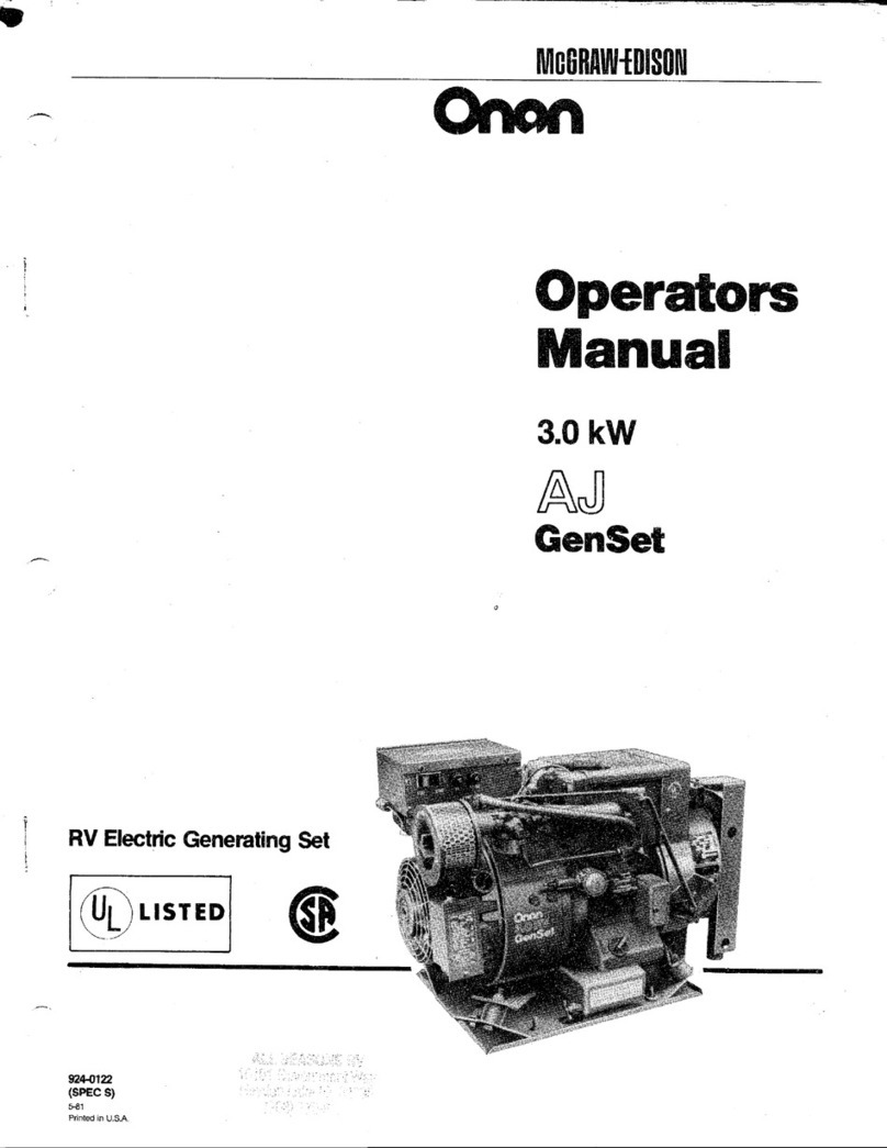
Onan 3.0 kW AJ GEN SET User manual

Onan
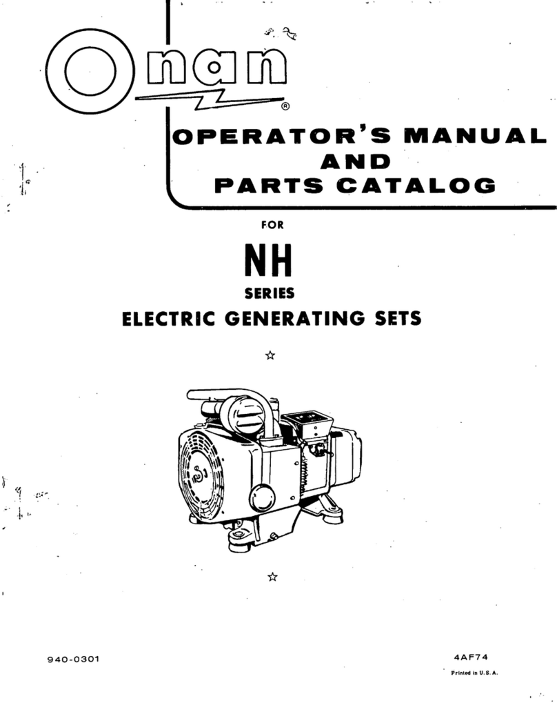
Onan NH User manual

Onan
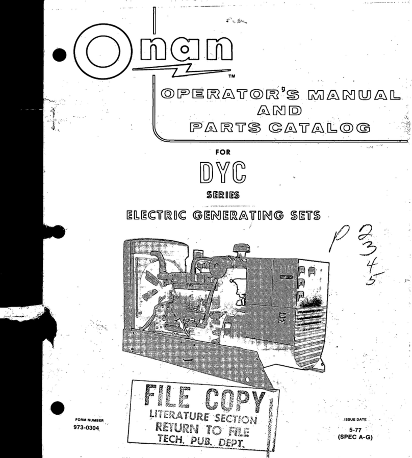
Onan DYC Series Instruction Manual

Onan
Onan BGM Series User manual

Onan
Onan 16004 Series User manual

Onan
Onan NH Instruction Manual

Onan
Onan MDJF Series Instruction Manual

Onan
Onan DYG Series Instruction Manual

Onan
Onan Genset LK Series User manual

Onan
Onan 6GO-F User manual
Popular Inverter manuals by other brands

Platinum
Platinum 5500 R3-S2B User and installation manual

CE+T Power
CE+T Power TSI VEDA user manual

LeCroy
LeCroy PXA125 user manual

Xantrex
Xantrex SW Series owner's manual

SunSynk
SunSynk SUNSYNK-8K-SG01LP1 Installer manual

Northern Lights
Northern Lights L944D, M944W, NL944D2, M30CW, M944T, NL944T2, and... Operator's manual